



Abstract
This paper presents the design and development of a robust electrospinning set-up for the processing of polymer composites at the nanoscale. A robotic-controlled movable dual-nozzle (keeping the rotating collector at a fixed position) set-up with two power supplies is presented for nanocomposite electrospinning. We studied the effect of different angles between two nozzles on the physicochemical properties of composite PU/PA6 electrospun mats obtained from this electrospining set-up. Scanning electron microscopy (SEM) images of the mats indicated that the diameter of the nanofibers and their evenness was affected by the angle between the nozzles. The effect of angle (between the nozzles) on the mechanical strength of the composite mats was also evaluated. The hybrid mat obtained from the dual- nozzle system was found to be mechanically stronger than the individual fibrous mat. Furthermore, the mechanical strength of the composite mat could be increased by decreasing the angle between the tips of the nozzles.
Introduction
Electrospinning of polymer solutions (or melts) has gained much attention in the last few years as an easy, cheap and effective method to produce nanofibers.1–3 The area of control and manipulation of the nanofiber structure has recently received widespread attention in electrospinning technology. Different parameters as well as electrospinning set-ups have been reported to change the physicochemical properties of fibers during electrospinning.4,5 Mainly two types of parameters, i.e. material and process parameters are believed to affect physicochemical properties of fibers during electrospinning. 6 From a material/processing standpoint, several factors can have an influence on the formation of fibers from polymer solutions through electrospinning. These parameters are intrinsic properties of a solution, such as viscosity, conductivity, surface tension, polymer molecular weight and concentration, and operating conditions, such as applied voltage, temperature, humidity, nozzle diameter, solution flow rate, spinneret–collector distance, and motion of the collector.7–9 Recently, the synthesis and design of hybrid materials have generated great interests in the fields of material science. Composite nanofibrous materials formed by blending different polymers (or polymer/inorganic materials) with different properties are attractive for the purpose of creating new materials with new or enhanced properties compared with a single material. The hybrid material can improve the performance of the mechanical, thermal, optical, electrical, antimicrobial, biological, antifouling, and catalytic properties of a polymer matrix.10–14 However, electrospinning from the blend solution of two or more polymers becomes quite difficult because of the lack of proper common solvent for different polymers. Furthermore, fiber formation parameters such as concentration, viscosity, applied voltage, etc. are different for various polymers, and it is quite difficult to maintain these properties by blending the polymers. Therefore, a multi-nozzle electrospinning (MNE) set-up is used to overcome the above-mentioned limitation. The properties of fibers can be affected by the configuration of nozzles in multi-nozzle electrospinning. Gu et al. prepared a poly(vinyl alcohol)/polyurethane (PVA/PU) nanofiber composite mats using dual-jet electrospinning, with the two spinnerets oriented perpendicular (90°) to the collector. 15 They reported a significant increase in tensile strength and elongation, and improved thermal stability of the PVA/PU nanocomposite as compared with pure PVA and pure PU. Lingaiah et al. used single- and dual-jet electrospinning of nylon-66. In their dual-jet electrospinning set-up, the jets were oriented perpendicular to the collector (rotating drum), but the two syringes were placed either 90° (side and top of collector) or 180° (opposite sides of collector) to each other. 16 Their results showed a general increase in tensile strength for the dual-jet electrospun nanofibers when compared with those obtained by single-jet electrospinning.
Here, we present a multi-nozzle electrospinning system (made in our laboratory) in which two different polymer solutions are used for making composite fibers using two nozzles with separate power supplies. Our set-up is different than the reported multi-nozzle electrospinning set-ups because we use a robot-controlled movable multi-nozzle system (fixed collector) with tunable angle between the tips of the nozzles. Furthermore, we studied the effect of the angle (called configuration) between the tips of two nozzles in the physicochemical properties of the electrospun mats. In this system, the nozzles are placed at one side of the collector and the angles between the tips of the two nozzles could be controlled. We evaluated the present set-up by checking the changes in nanofiber morphology and their effect on mechanical strength of the nanocomposite fibers. In this study, we used polyurethane (PU) and polyamide-6 (PA6) to produce nanofiber composites by angled two-nozzle electrospinning because PU could not be dissolved in formic acid (a solvent of PA6) nor can PA6 be dissolved in N, N-dimethylformamide/methyl ethyl ketone (DMF/MEK) (a solvent of PU). Moreover, to the best of the authors’ knowledge, this may be the first report about the nanocomposite of PU/PA6 by electrospinning. Thermoplastic PU and PA6 are highly used polymers because of their excellent properties. Polyamide (nylon-6) nanofibrous mats are commercially used for water filtration. However, the degradation and swelling caused by water can decrease its filtration efficiency. We can control the fast degradation and swelling of polyamide fibers by making composite fibers with PU. An electrospun nanocomposite mat of PU and PA6 may exhibit properties shown by both individual polymers and through this combination becomes a new material for different applications. For comparison, pristine mats of PU and PA6 were also fabricated with the same parameters using single-nozzle electrospinning.
Materials and methods
Materials
PA6 (Mw ≈ 35,000) in pellet forms and high-molecular weight thermoplastic PU (Estane X595A-11) were purchased from Kolon Industries and Lubrizol Advanced Materials, respectively. The PU and PA6 pellets were kept in an oven at 80°C for at least 3 h prior to dissolution in solvents. DMF and MEK were purchased from Showa Chemicals and Junsei Japan, respectively. Formic acid was received from OCl Co., Ltd. Korea. All reagents received were used without any further purification. We separately prepared 10 wt% PU in DMF/MEK (50/50, wt%) and 20 wt% of PA6 in formic acid solvent and these were kept overnight with magnetic stirring.
Multi-nozzle electrospinning
Electrospinning was carried out using the set-up we designed, which is shown in Figure 1. It was composed of two separate high-voltage power supplies (Nano NC: 60 kV, 2 mA), a cylindrical collector with Teflon sheet, two 10 ml plastic syringes, two metal capillaries (nozzles) with inner diameters of 0.51 mm (21 G), two syringe pumps, and a 1-D robot system that moves laterally controlled by LabVIEW 9.0 program (National Instrument). The whole set-up was placed in a sealed chamber, with an automatic exhaust system, dehumidifier and heating system. During the electrospinning, the nozzle moved sideways (i.e. horizontally, back and forth) on its axis for a distance of 150 mm and a linear speed of 100 mm/min. The nozzle tip-to-collector distance was held constant at 50 mm. For single-nozzle electrospinning, 4 ml of neat PU or PA6 solution was electrospun onto a grounded cylindrical collector. In this set-up, only one syringe and one nozzle were used. The nozzle was perpendicularly oriented to the collector. For two-nozzle electrospinning, two syringes, two nozzles, and two power supplies were used. Both power supplies had identical voltages. Each syringe separately contained 2 ml of solution of PU and PA6. The angle between the tips of two nozzles was maintained at either 100° or 90° (referred to as the nozzle configuration). Both nozzle tips were 150 mm away from the collector. Electrospinning was carried out at 24°C and 35% humidity with an open chamber. After electrospinning, the nanofiber membranes were dried in an oven at 80°C for 48 h.
(a) 3D schematic and (b) photograph of a multi-nozzle electrospinning system.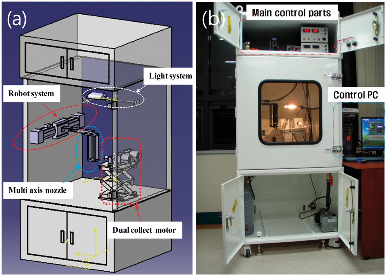
To study the effect of different configurations (angle between the tips) with robot-controlled speed, we designed a new electrospinning set-up as shown in Figure 1. Since most of the polymers used for composite materials have neither common solvent nor the same spinnable applied voltage, we developed a multi-nozzle set-up with two separate power supplies. We believe that this model can be used for making commercial composite materials utilizing two polymers with no common solvent and their solutions requiring two different applied voltages for spinning. The most important feature of our set-up is the moveable multi-axial nozzle which can easily be controlled via a robot system as shown in Figure 2. The robot can move horizontally to a maximum stroke of 700 mm. A robotic system having a linear servo motor (TPC for one axis linear motor) to enable micro-step control was used. The robot can be controlled through a computer PCI bus controller (National Instruments PCI-7390) using the LabVIEW 9.0 program interface. We can precisely control the robot's acceleration, speed and stroke distance. To change the nozzle angle (configuration), we provided an angle marker at the bottom of the multi-nozzle base, made of polycarbonate. Furthermore, to identify the mechanism of the formation of turbulence, we used a DSLR camera (SONY Next-5). The system consists of noise filter in front of the power supply for stability. To control the stroke position, we provided a limit photo sensor to the robot. Furthermore, we developed a terminal block for the easy connection of the robot to the PCI-7390 board.
(a) Multi-nozzle system and (b) robot used in the electrospinning set-up.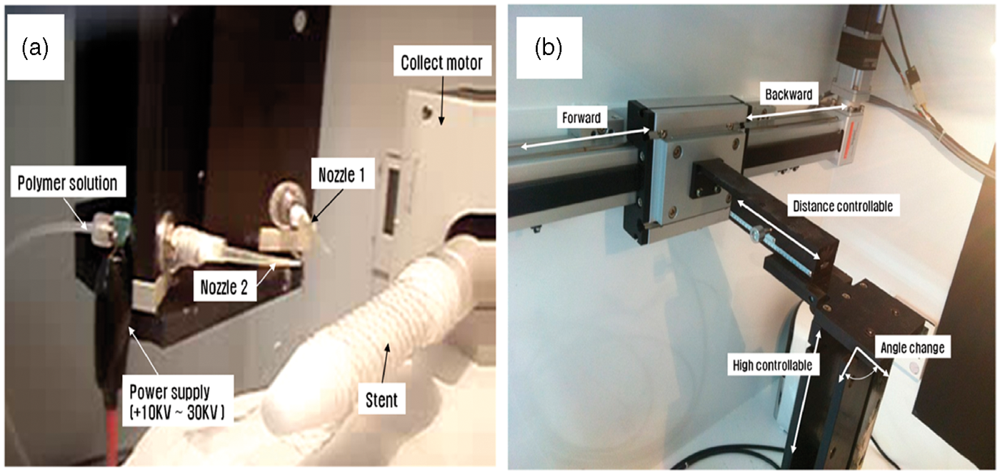
The LabVIEW 9.0 system interface control program is shown in Figure 3(a). The automatic operation of the multi-nozzle system with constant speed has no error due to the robot system. To verify the accuracy of the robot, set-ups at 5, 10, 15, 20, 25, and 30 cm were operated. To measure the trajectory of the robot system in real time, we used a Quadrature Encoder at a sampling rate of 1 kHz. Figure 3(c) shows that the trajectory of the robot moving horizontally from its minimum to maximum distance was 100% accurate.
(a) Robot-controlled front panel program, (b) result of the trajectory of robot movements and (c) comparison of maximum and minimum movement.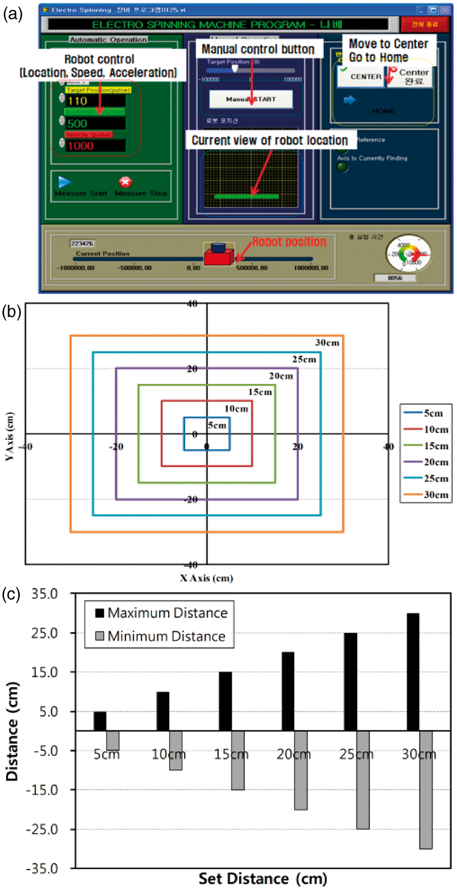
Characterization
The morphological properties of all samples were observed using scanning electron microscopy (SEM; Hitachi X-650, Japan). The fiber diameter distribution and pore size were determined using Image J (NIH, USA) software. An average of 50–100 nanofiber diameters from the SEM images was calculated and the histogram was prepared. Fourier transform infrared (FT-IR) spectra were measured using Spectrum GX (Perkin Elmer, USA). The tensile properties of the composite mats were obtained using an Instron tensile test machine with 100 N limit (Lloyd Instruments). Dog-bone specimens taped on a paper frame were prepared based on ASTM D882-10. The gage length was 25 mm and crosshead speed was 5 mm/min. Five specimens were tested and averaged for each sample for comparison. The thicknesses of the specimens were measured using a digital microcaliper (Mitutoyo Absolute, Japan) with an accuracy of ±0.5 µm.
Results and discussion
Morphology of fibers
The low yield of nanofibrous mats from electrospinning limits its industrial use. Therefore, different research groups reported modified electrospinning set-ups by using a multi-nozzle system.17–22 However, no one has reported the effect of the angle between the nozzles and a movable robot-controlled multi-nozzle system (fixed collector) on the physicochemical properties of electrospun mats. The morphology of different electrospun mats is shown in Figure 4. It shows that porous, ultra-fine fibers in the nanometer range, and randomly distributed non-woven fibrous mats were fabricated. Pristine PU nanofibers showed generally larger fiber diameters as compared with pristine PA6 and PU/PA6 composite. Some beads were seen on the PU nanofibrous mat, which could be attributed to relatively low viscosity or short distance between the spinneret tip and the collector.
23
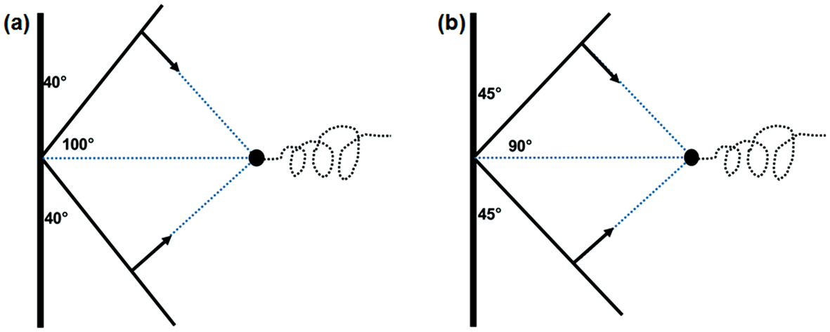
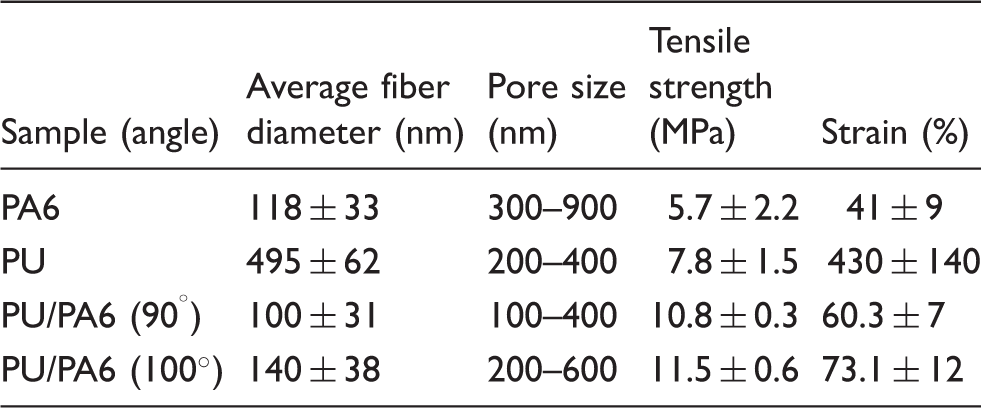
The pristine PU and PA6 nanofibers were more straight and randomly oriented (Figures 4(a) and (b)) while PU/nylon-6 nanofibers (Figure 4(c) and (d)) are very random, curvy, with relatively uniform diameter. Since the curvature is a consequence of the entropic shrinkage that occurs when PU is spun and interacts with the relatively stiff PA6 fibers, the fiber orientation should be different in composite fibers (obtained from a dual-nozzle system) compared with pristine fibers. Furthermore, differential shrinkage might be possible due to solvent evaporation. It should be noted that pristine PU and PA6 nanofibers were electrospun using a single spinneret oriented perpendicular to the cylindrical collector while the PU/PA6 composites were formed by using two spinnerets with an angle of 100° or 90° between the tips of two nozzles. The orientation of nozzles at two different angles is shown in Figure 5. The distance between the tips of the two spinnerets was 50 and 40 mm for 100° and 90° configurations, respectively. It is clearly observed from this figure that the interaction of two polymer jets could remain on the electric filed for a longer time at 90° orientation compared with the 100° orientation. Therefore, we could expect some changes in the physicochemical properties of the obtained mat as was observed from SEM images, mechanical properties, and FT-IR analysis. Furthermore, faster mixing of two jets of different polymers at 90° could experience more antisolvent effect compared with the 100° orientation. The fiber diameter distributions of pristine PU and PA6 as well as composite PU/PA6 (at 100° and 90° configurations) are shown in Figure 4(a’), (b’), (c’) and (d’), respectively. Furthermore, their average fiber diameter and pore size is expressed in Table 1. Although the diameter of hybrid fibers was smaller than that of pristine polymer fibers, the pristine PU fibers are larger compared with the fibers in the blend because of the lower charge in the single-jet electrospinning. The fiber diameter distributions appear to be different from sample to sample because of the nature of electrospun nanofibers to have uneven fiber diameter distribution due to the different bending and axisymmetrical instabilities of the jet depending on the nature of polymers and their solvents. The uneven diameter distribution was decreased in composite mats as compared with the pristine electrospun mat which is similar to the result reported by Lingaiah et al.
16
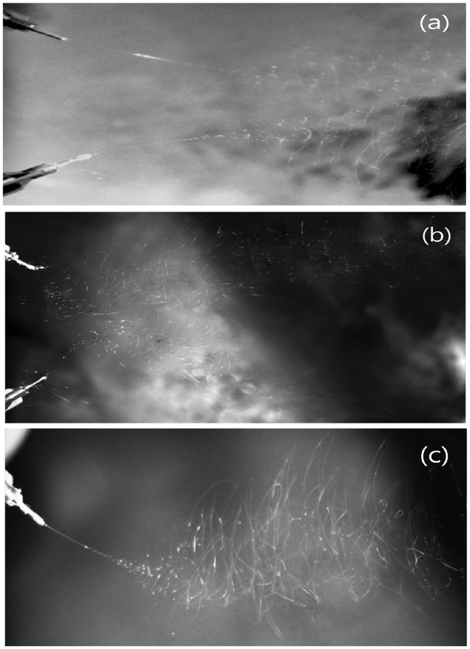
The possible cause of less uneven diameter distribution may be due to the increased applied voltage caused by two power supplies, since each of the Taylor cones and their jets were interacting in the applied electrical field when the robot is operated (Figure 6(b)). The common ground for different power supplies for two nozzles can increase the electrical field and consequently causes the fiber attenuation. Kim et al. also stated that a secondary electrode is useful to obtain thinner homogenous fibers in large scale using multi-nozzle electrospinning system.
24
The more instability of jets at 90° due to the charge–charge repulsion within the fibers might be the cause of more fiber attenuation. The turning of the fibers at 90° allows for a lower velocity, so a longer time in a region saturated with solvent causes more attenuation of the fibers. Therefore, our electrospinning set-up can increase the evenness distribution of fibers which is the limitation of common multi-nozzle electrospinning set-up (caused by two power supplies). Thinner fibers and their evenness distribution are important aspects of electrospun mats for different applications. In the case of PU/PA6 nanocomposite, their spinneret configuration (90° angle) could have made more bending instabilities thereby producing more wavy non-woven nanofibers as compared with the 100° configuration. The possible cause of this different fiber morphology can be explained with the help of the jets overlapping condition. With the 90° configuration (40 mm distance between the tips), two jets of different polymers were overlapping with each other faster than in the 100° configuration (50 mm distance between the tips) and could remain for a longer time in the increased electrical field before collecting on the surface of the collector. The faster overlapping of jets can easily increase the charge density of combined spinnerets because of two power supplies with common grounding. Furthermore, a movable-nozzle system allowed faster overlapping of two spinnerets which is clearly observed in Figure 6. This shows that the spinnerets of the robot in operating mode (Figure 6(b)) take shorter time for overlapping as compared with the robot in non-operating mode (Figure 6(a)).
SEM images (a)–(d) and corresponding diameter distributions (a’)–(d’) of electrospun nanofibers of: (a) pristine PU, (b) pristine PA6, (c) PU/PA6 with the 90° configuration and (d) PU/PA6 with the 100° configuration. Schematic diagram showing (a) 100° and (b) 90° orientation of dual nozzles. Photographs showing the jet formation behavior from (a) a multi-nozzle system when the robot is not operated, (b) a multi-nozzle system when the robot is operated, and (c) a single-nozzle system. Average fiber diameter, pore size, tensile strength, and strain of different mats (fiber diameter and pore size were measured using Image J (NIH, USA) software)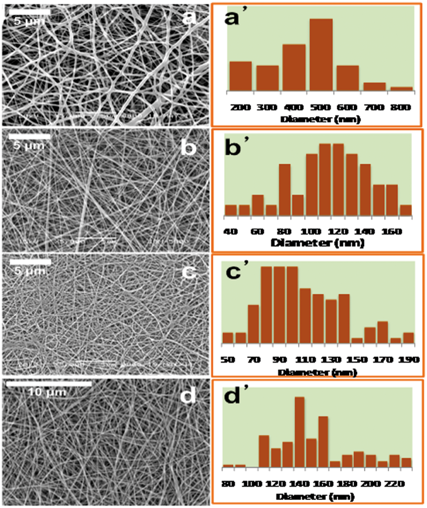
Mechanical properties
Figure 7 shows the typical stress–strain behavior of the electrospun nanofibers. The summary of tensile strength and strain obtained from five specimens of each mat is shown in Table 1. The pristine PU nanofibrous mat showed better mechanical properties than the pristine PA6 mat because the PA6 nanofibrous mat was quite brittle compared with PU (material properties). The PU/PA6 composite mat obtained from multi-nozzle electrospinning has better tensile strength than either of pristine PU or PA6 nanofibers. The strain percentage of the composite mat was less than pristine PU but more than PA6. The elastic behavior of PU might be the cause of this result.
25
The possible cause of the increased mechanical properties of the composite mat may be due to the effective interaction between PU and PA6 molecules caused by effective jet formation. The cause of formation of thinner evenness fibers in two-nozzle electrospinning as compared with the single-nozzle was clearly seen from the photograph of the two set-ups as shown in Figure 6. In the dual-nozzle system, the jet diameter and cone depth (Figure 6(a) and (b)) is smaller than that of the single-nozzle system (Figure 6(c)). These changes were more significant when the robot was in the operating condition (Figure 6(b)). The larger jet diameter covers a greater area for the fibers than that of the smaller jet diameter.
26
As a result, the density and evenness of fibers became greater in dual-nozzle system than that of single nozzle system.
Typical tensile stress–strain curves of different electrospun mats.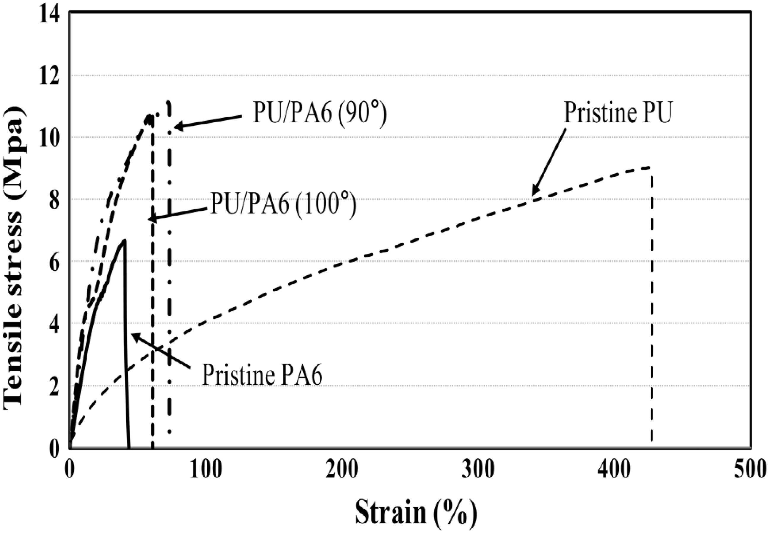
Therefore, the mechanical strength of the composite mat obtained from the dual-nozzle system is greater than the pristine mat obtained from the single-nozzle system. Furthermore, the dual jets with the same charge will experience electrostatic repulsion and change the fiber orientation as well as diameter of the fibers compared with the single-jet system (Figure 4). Since web strength is also a function of the fiber orientation, the mechanical strength of composite fibrous mat should be increased in dual-jet electrospinning. Moreover, the charge–charge repulsion of the jet is more pronounced in 90° configurations compared with the 100° (Figure 5). This repulsion allows for the lower velocity and provides a longer time in a region saturated with solvent which produces more attenuation in the fibers. Therefore, the composite mat obtained from 90° configurations is mechanically stronger than that from 100°. Moreover, thinner fibers with more directionally oriented (partially aligned) towards the collector drum rotating direction caused by two separate power supplies could enhance the mechanical strength of the composite mat. 16 Unlike the reported multi-nozzle set-ups, 27 our dual power supply for separate nozzles prevents the strong Coulombic repulsion between the jets (Figure 6(a) and (b)). Faster overlapping of jets with longer bending instability time may cause the good physical connection between the fibers of two polymers. This physical connection may be at the molecular level by means of a newly formed hydrogen bond between PU and PA6 molecules.
FT-IR spectra
To confirm the polymer interaction is either physical or chemical at the molecular level, we performed an FT-IR study of different mats. Figure 8 shows the FT-IR spectra of the electrospun pristine and composite mats. The characteristic peaks of PU nanofibers were observed similar as reported in the literature
28
and that of PA6 was similar to our previous work.
6
Composite mats also showed similar spectral pattern (i.e. they kept their structural independence) without any noticeable change which confirmed that there is no any chemical interaction between polymers. However, it was observed that the band at 3400–3100 cm−1 (OH stretching) was broadened in the composite mat as compared with the pristine mats and the band at 1538 cm−1 (amide II) of pristine PA6 shifted towards higher frequency (Figure 8) in he composite mats. This is an indication of interaction of PA6 with PU by means of the formation of new hydrogen bond.6,29 This change is possible due to the specific interactions that influence the vibrational frequency of functional groups as detected through the FT-IR spectra. The functional groups such as C=O and NH in PA6 can interact with ether, ester, urea or amide functional groups of PU for the formation of new intermolecular hydrogen bonds.
FT-IR spectra of electrospun mats (a) pristine PA6, (b) PU/PA6 at 100° configuration, (c) PU/PA6 at 90° configuration, and (d) pristine PU.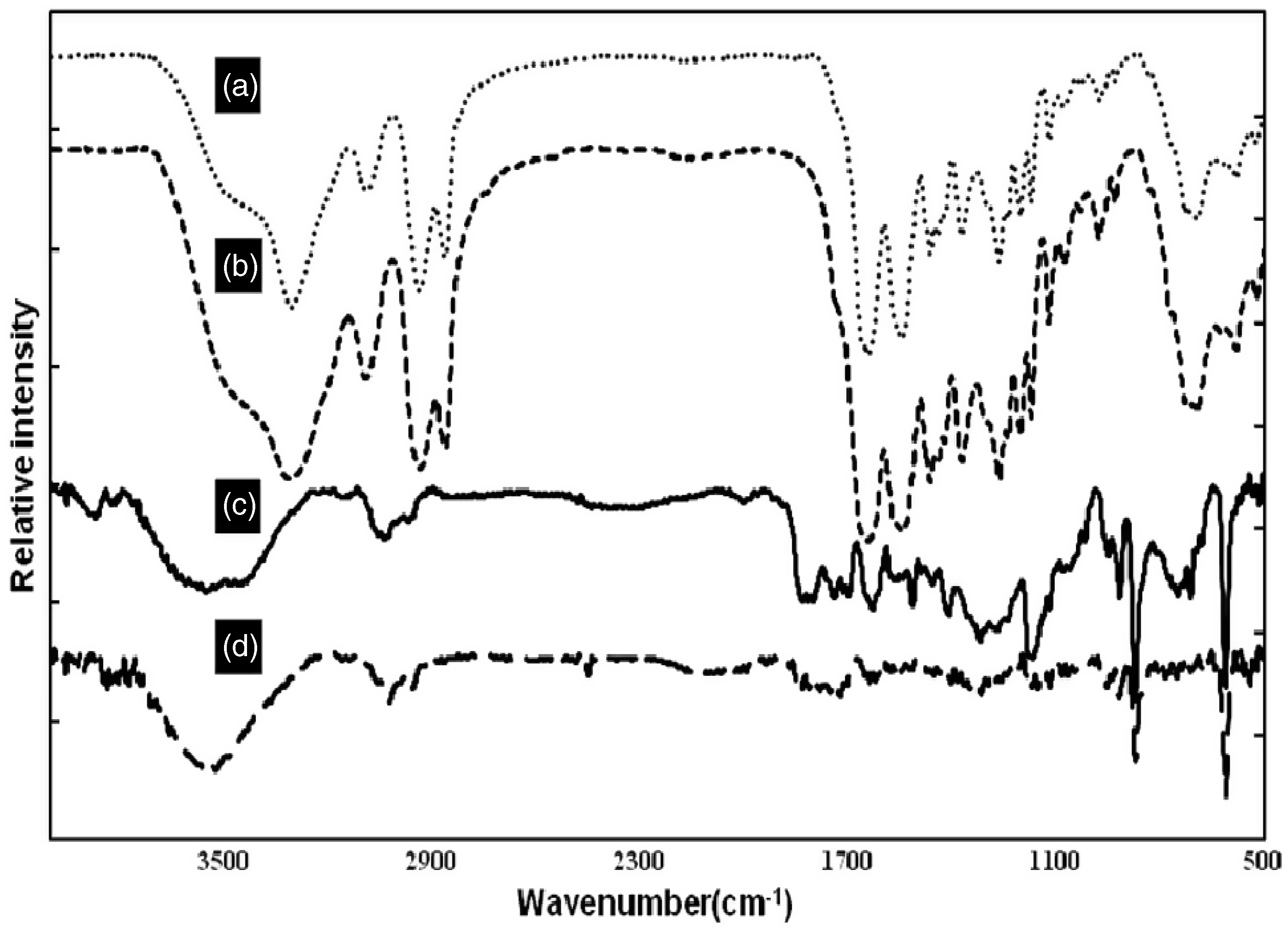
Furthermore, in composite mats at 90° configuration, the FT-IR bands of PU dominated the FT-IR band of PA and vice versa for the 100° configuration. These changes attributed from the precipitation of polymer were caused by anti-solvent during the overlapping of jets. We performed an experiment exploring the effect of anti-solvent by precipitating PU and PA6 solutions into formic acid and DMF/MEK solvent, respectively. It was observed that the precipitation of PA6 from formic acid solution is faster in the DMF/MEK solvent system than that of PU from the DMF/MEK solution in formic acid. At 90° configuration, the mixing of two jets was fast which might cause the faster solidification of PA6 and PU could deposit on the surface of PA6 as it took a longer time to precipitate. Consequently PU could dominate the PA6 bands (Figure 8(d)). However, in the 100° configuration, the jets of two solutions mixed more slowly than in the 90° configuration and faster evaporation of DMF/MEK (MEK is highly volatile) helped to dominate PU bands as its fibers should be coated with PA6 (Figure 8(c)). The effect of mixing of different solvent systems (used in this study) was carried out and no change was observed. Furthermore, different polymers were wet spun into a bath of the other solvent system. The collected PA6 fibers in the DMF/MEK bath showed slightly increased fiber diameter; however, PU fibers collected into formic acid not only showed the slightly increased fiber diameter but also showed the fused morphology (point-bonding between the fibers). The formation of such a point-bonded structure was also observed in composite mats (Figure 4(c) and (d)) because slow evaporation of formic acid could allow the adherence of PU fibers at crossover points which could also increase the mechanical strength of the fibers. Therefore, one can except that there might be some physicochemical changes on the individual polymer fibers when they are collected by angled dual-nozzle systems using different polymer solutions with an anti-solvent effect.
Since our concern was to reduce the swelling and degradation rate of electrospun PA6 mat during water filtration by making a composite mat with PU, we evaluated these properties by keeping the pristine PA6 and composite mat in water for 1 week. Figure 9 clearly shows that the pristine PA6 fibers undergo swelling where as there is no noticeable swelling of the fibers in the composite mat. The swelling of fibers may cause a decrease in pore size and porosity of the mat and consequently decrease in the filtration efficiency. Therefore, the composite fibrous mat of PU/PA6 has great potentiality in water filtration.
SEM images of electrospun mats after 1 week of water treatment: (a) single-nozzle pristine PA6 and (b) dual-nozzle PU/PA6 at 90° configuration.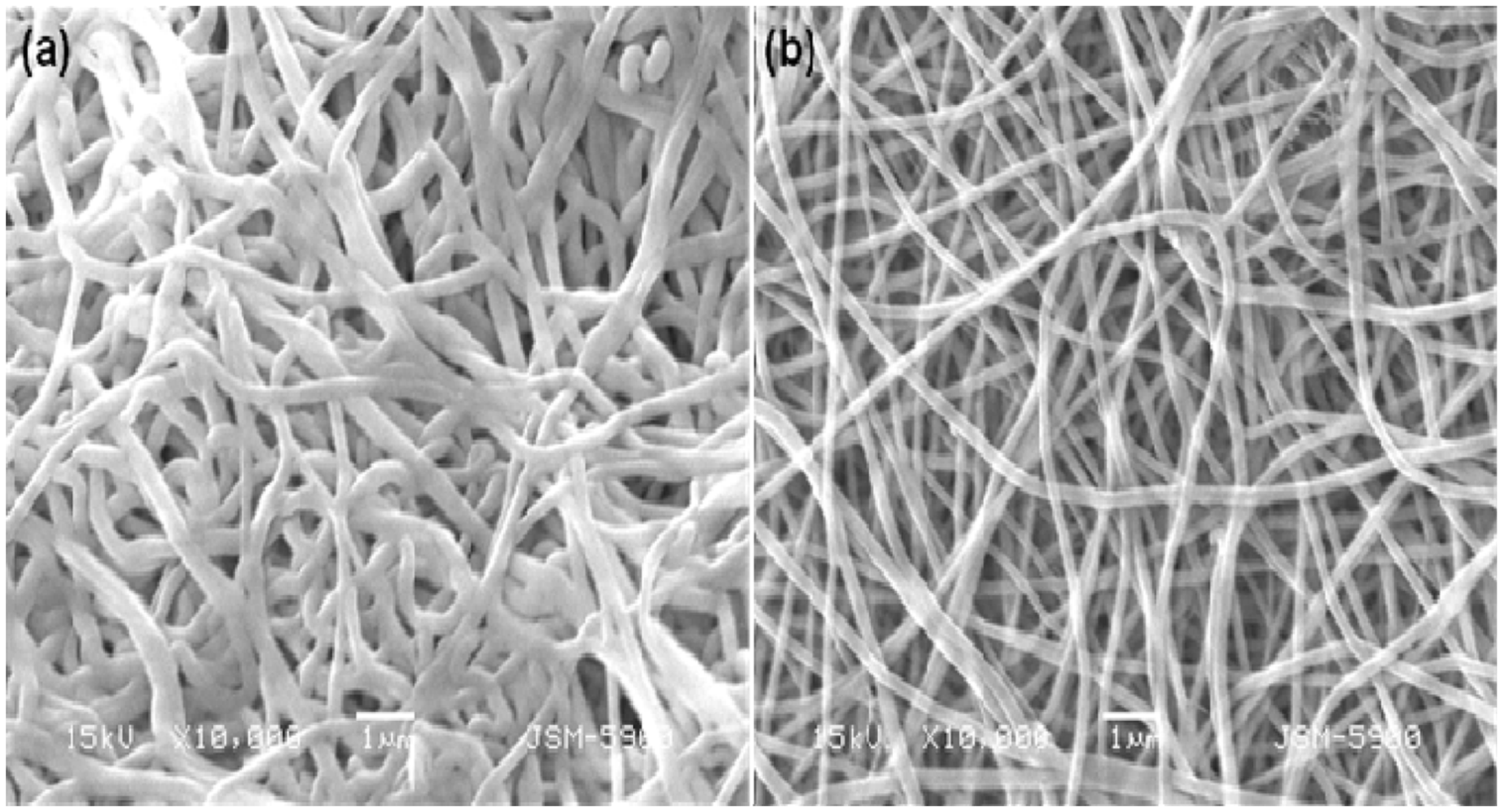
Conclusion
In this study, we developed a new prototype electrospinning set-up for the production of nano-composite fibrous mats. The goal of this investigation has been to build a basis to study the effect of a movable angled multi-nozzle (robot-controllable) set-up on the physicochemical properties of electrospun nanocomposite mats. The decreased fiber diameter with more even distribution of nanofibers is easily achieved with this new set-up. Our results showed that the fiber distribution and tensile properties of electrospun mats were affected with changing the configuration of nozzles (i.e. the angle between the tips of the nozzles). The authors are currently using this set-up for a wide range of polymers (having no common solvent) in the hope of forming even finer fibrous mats by using different applied voltages which will highlight the limitations of single-power-supply multi-nozzle set-ups.
Footnotes
Funding
This research was supported by a grant from the Korean Ministry of Education, Science and Technology through the National Research Foundation (Water Treatment Project no. 2011-0011807).