




Abstract
The tensile behaviors of 3-D woven fabric under high strain-rate states, i.e. tensile impact behaviors, are important for the design of the fabrics and the reinforced composites under impulsive loading. This paper reports the testing and the numerical simulation of the impact tension behaviors of 3-D woven fabric under high strain rates compared with those under quasi-static tension. The tensile behaviors of 3-D orthogonal woven fabric (3DOWF) were investigated using a MTS 810.23 material testing system and a self-designed split Hopkinson tension bar apparatus, under a wide range of strain rates (0.003–2308/s). The tensile stress–strain curves obtained from the quasi-static and high strain rates were used to analyze the rate-sensitivity of 3DOWF tensile behaviors. It was found that both the tensile strength and the failure strain increased with increases in the strain rate. The two-phase tensile stiffness phenomenon of 3DOWF under high strain rates has been observed experimentally. A microstructure model combined with finite element analysis was established to explain the tensile failure mechanisms of 3DOWF under high strain rates. It was found that the fabric architecture influences the stress wave propagation, thus leading to the two-phase tensile stiffness phenomenon in the stress–strain curve under high strain-rate tensions.
Keywords
High strength 3-D fabrics and composites fabricated from high performance fibers (e.g. carbon fiber, aramid fiber, etc.) are ideal materials for dynamic loading applications. Compared with laminated composites, 3-D fabrics and composites have higher interlaminar shear strength and fracture toughness. These features lead to more potential applications of the 3-D composites in impact protection areas than of the laminated materials. The key to the precise design of the 3-D fabrics and composites for impact protection is to characterize their mechanical behaviors under high strain rates. Understanding the tensile behaviors of 3-D woven fabric under various strain rates, especially high strain rates, will be beneficial for the analyses and designs of 3-D woven composites.
The mechanical behaviors of fiber materials under various strain rates have been investigated at the levels of the fiber tows and the fabrics, respectively. At the fiber tows level, the tensile behaviors of parallel filament tows have been tested by several investigators. Cansfield et al. 1 found significant strain-rate effects of the tensile behaviors of ultra high molecular polyethylene (UHMPE) filament tows. Schwartz et al. 2 reported significant strain rate (0.004–1/min) and gauge length effect on the high strength polyethylene. Wagner et al. 3 studied the dependence of the tensile strength of low-, medium- and high-modulus pitch based carbon and Kevlar 29, Kevlar 49 and Kevlar 149 para-aramid fibers. Amaniampong and Burgoyne 4 tested the effect of strain rate from 3 × 10⁻⁴/s to 3 × 10⁻²/s on the failure stress and strain of Kevlar 49 yarns. Wang and Xia5,6 assessed the strain-rate sensitivity of the mechanical properties of three different fiber bundles: E-glass, Kevlar 49 and polyvinyl alcohol (PVA). It turned out that the mechanical properties of all three fiber bundles had rate dependence, except for the elastic modulus of PVA fibers. Zhou et al. 7 studied the tensile mechanical behavior of the T700 fiber bundles at strain rates ranging from 10−3/s to 1300/s. The results showed that the strain rate had negligible effects on the modulus, the ultimate strength and failure strain of the T700 fiber bundles. Farsi et al. 8 investigated the quasi-static and dynamic tensile behaviors of five different fibers (Kevlar 129, Kevlar KM2, Kevlar LT, Twaron and Zylon) using hydraulic and Hopkinson bar testing methods and the rate dependency of the failure strength of each yarn was quantified. Tan et al. 9 tested Twaron® yarn under different strain rates using a load frame and a split Hopkinson tension bar (SHTB). The tensile results showed that Twaron fiber was strain-rate sensitive; the modulus, failure strain and stress increase with strain rates from 0.0003 to 480/s. Zhu et al. 10 carried out quasi-static and dynamic tensile tests on basalt fiber bundles using a MTS 810.23 tester and an SHTB under the strain rates of 10−3 to 3000/s. Testing results showed that the mechanical properties of the basalt filament tows were sensitive to the strain rate. At the fabric level, Shim et al. 11 tested the tensile behavior of Twaron® CT 716 fabric at strain rates ranging from 10−2 to 550/s using both a load frame and an SHTB apparatus. Experimental results indicated that Twaron® was highly strain-rate dependent; the tensile strength and modulus increased with the strain rate while the failure strain decreased. Naik et al. 12 conducted low strain-rate tension tests on Kevlar 49 and Zylon fabrics using a servo hydraulic load frame. Zhu et al. 13 conducted tensile tests on Kevlar 49 plain weave fabric with two different gauge lengths (25 and 50 mm) at strain rates ranging from 25 to 170/s using an MTS high-rate servo hydraulic testing machine. Results showed that the dynamic material properties in terms of Young’s modulus, tensile strength, maximum strain and toughness increased with increasing strain rate. Seidt et al. 14 performed quasi-static and dynamic tensile tests on Kevlar 49 fabrics in a plain weave at strain rates of 10−4 to 1500/s using both a hydraulic load frame and an SHTB system. The results indicated that the modulus of Kevlar 49 fabric was not sensitive to the strain rate and the peak stress was higher at 1500/s than at 10−4/s and 500/s. Most of the previous studies have been focused on plain weave fabrics. In the present work, the focus was extended to tensile testing of 3DOWF to study the influence of fabric architecture on the tensile behavior. The MTS 810.23 materials testing system and a self-designed SHTB apparatus were used to obtain the tensile behaviors of 3DOWF under quasi-static and high strain-rate states, respectively. The strain-rate effects on the tensile stiffness, strength and failure strain were analyzed both experimentally and by numerical simulation. As far as the authors know, this is probably the first attempt to characterize the tensile behaviors of 3-D woven fabric under a high strain-rate state, although some work has been done on the high strain-rate tension of 2-D woven fabrics, as mentioned above. We hope that such an attempt will be helpful for understanding the failure mechanisms of 3-D woven fabric under tensile impact. Furthermore, this investigation could be extended to the understanding of the tensile impact behaviors of the 3-D woven composites.
Material and experimental details
Fabric samples
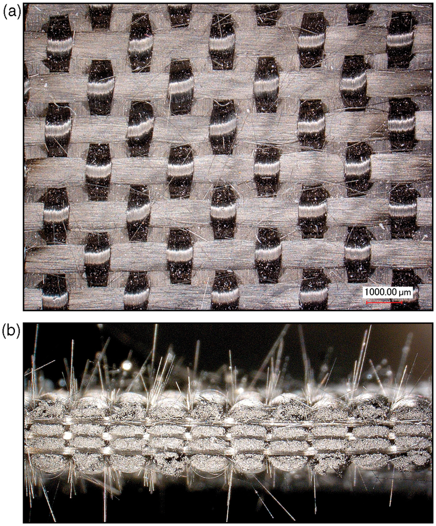
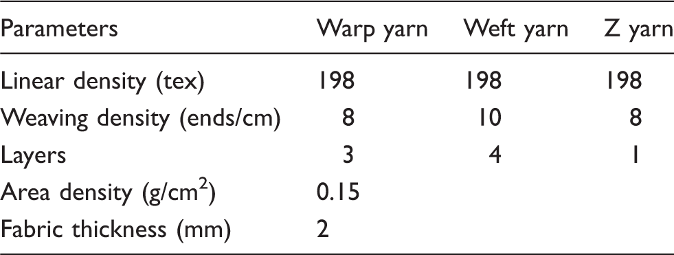
The 3DOWF samples were woven from Torayca® carbon fiber tows (T300 3 K, manufactured by Toray®, Japan), and the parameters are indicated in detail in Table 1. The specifications of 3DOWF are listed in Table 2. Figure 1 shows the fabric construction. The weft and warp yarns in 3DOWF were straight line and bonded with the Z yarns to form a stable fabric structure. The surface and cross-section of the 3DOWF samples are shown in Figure 2.
Architecture of 3DOWF. Surface and cross-section photographs of 3DOWF. Properties of T300 3 K carbon fiber tow Specifications of 3DOWF

In order to prevent the slippage between the fabric samples and the grip bars, two ends of the fabric sample were consolidated with resin to form composite and then glued into the slots of the incident bar and the transmission bar of the SHTB apparatus. As shown in Figure 3, the composite specimen is 110 mm (weft) × 12 mm (warp) and the effective fabric region is 10 mm (weft) × 12 mm (warp), with 40 weft yarns inside.
Photograph of a specimen of 3DOWF.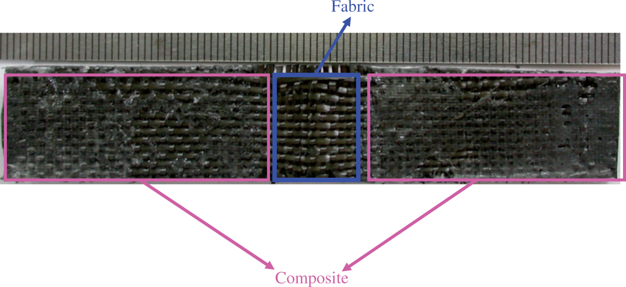
Quasi-static tensile tests
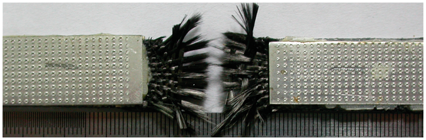
The quasi-static tensile tests along the weft direction were performed on an MTS 810.23 Material Testing System at a velocity of 2 mm/min. The gauge length of the specimen was set to be 10 mm. Hence the corresponding strain rate is Quasi-static tensile tests on the MTS 810.23 Material Testing System. Fracture morphology of 3DOWF under quasi-static loading. Strain–stress curves obtained from quasi-static tensile tests.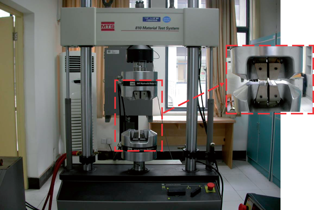

Dynamic tensile tests
The high strain rate (from 1672/s to 2308/s) tensile tests were conducted on an SHTB system as shown in Figure 7. Figure 8 presents the data acquisition and processing systems as well as details of the equipment for the high speed impact tensile tests.
Sketch of the testing system. Stress wave propagation history and locations of strain gauges (mm).
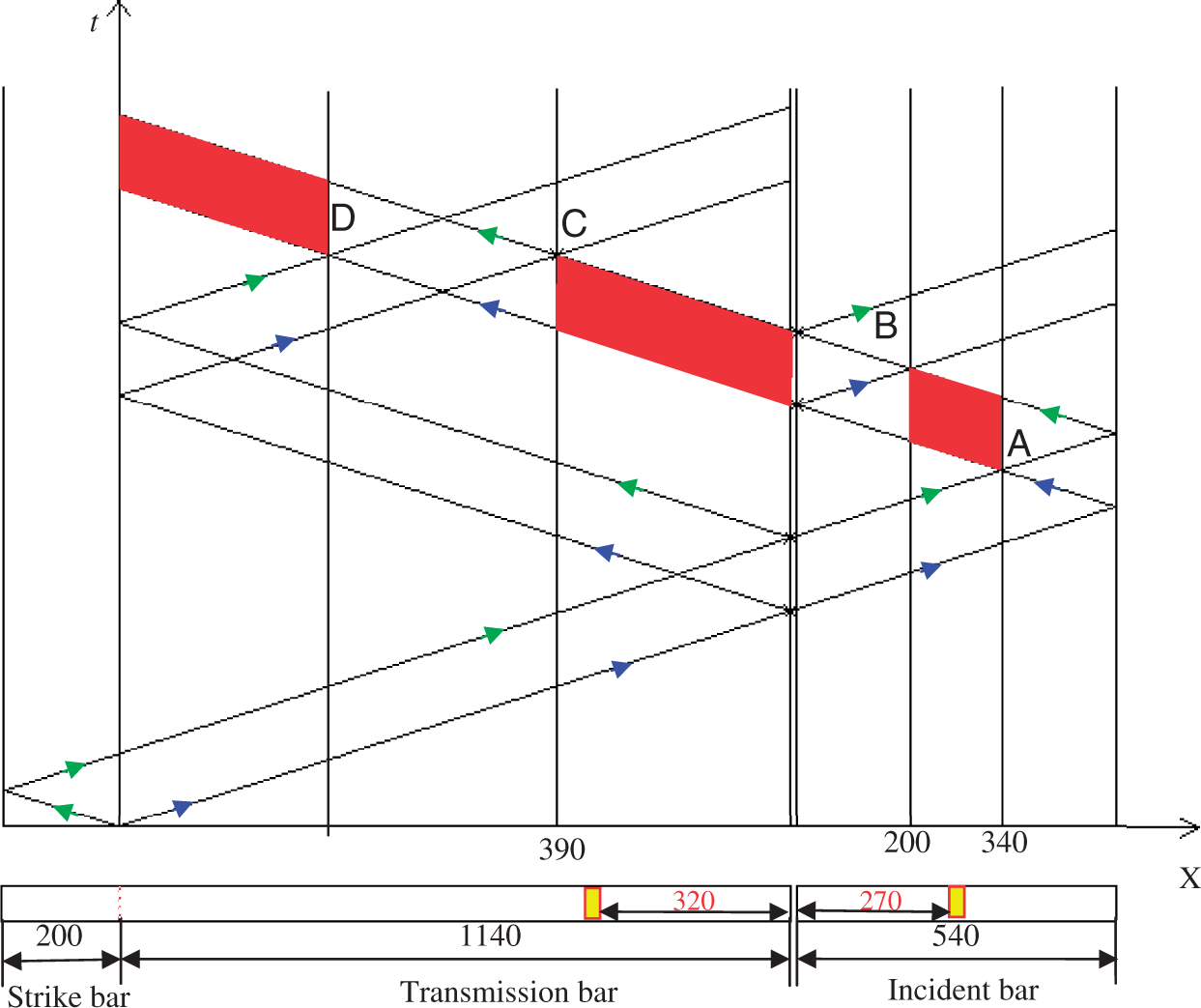
The SHTB apparatus used in the present investigation was equipped with a momentum trapping device, a gas gun with an inner diameter of 14.5 mm, a maraging steel incident bar and a transmission bar of diameter of 14.5 mm, while the length of the former bar was 1140 mm and that of the latter was 540 mm. The gas gun was operated by compressed nitrogen gas and can fire strike bars of different lengths. The length of strike bar was 200 mm. The impact velocity could be controlled by adjusting the gas pressure in the tank and different strain rates obtained accordingly. The signals from the strain gauges of 120 Ω were amplified 200–500 times with a super-dynamic strain amplifier, recorded by a high speed data acquisition card (PC-12406 40MSPS 12Bits 2 channels, made by Chengdu Watcher Technology Co. Ltd, China) and later retrieved by a PC for subsequent analysis. The data-sampling rate was 40 MHz for all experiments.
All the bars were strictly adjusted to be along a straight line to ensure a one-dimensional (1-D) propagation of the stress wave. Two composite ends of the specimen were glued into the incident and transmission bars with slots (50 mm long). Meanwhile, two pressure blocks (10 mm long) were sandwiched to determine the gauge length and transfer compressive wave, as shown in Figure 7. A compressive stress pulse is imparted to the transmission bar by impacting it with the strike bar. The compressive wave was then reflected at the free end of the incident bar and an effective tensile wave was generated. The strain rate was adjusted by changing the gas pressure supplied from the nitrogen tank. Because all the bars are of the same diameter (14.5 mm) and consist of a cold pressed bearing still (GCr15) with an elastic modulus of 207 GPa that allows elastic deformation only, even under high speed impact loading. Also, the length/diameter ratios of the incident and a transmission bar are 37 and 79, respectively. The effects of lateral inertia and the geometric wave dispersion under the high strain-rate loading can be neglected. The gauge length used in the tensile tests (10 mm) keep the specimen in a dynamic equilibrium state during the impact tension process. Based on 1-D wave theory15–17, the stress and strain of the specimen can be expressed as follows.

Based on the 1-D wave theory, the strain in 3DOWF can be deduced from the signals in the incident and transmission bars. The propagation history of the rectangular stress wave and the size of the bars are shown in Figure 8. To obtain the incident pulse, the reflected pulse and the transmitted pulse, two strain gauges were mounted on the designated position of the incident and the transmission bars as shown in Figure 8. The red area is the available position, in theory, for the strain gauges to be mounted while the yellow blocks are the actual positions of the two strain gauges in the tests.
Connections between 3DOWF coupons and bars
Benloulo et al., 18 Harding Ruiz 19 and Rodriguez et al. 20 developed a specially designed set of specimen clamps to mount the composite coupon between the incident and the transmission bar. The coupon was connected with the bar through a screw connection. The clearance between the screws of the bolt and the nut generated scattering of the elastic wave at a high rate of loading. To avoid uncertainties related to the effects of elastic wave scattering, the coupon was glued into two slotted incident and transmission bars, as shown in Figure 7. The bar was slotted, of length 50 mm and width 2.0 mm. The slot was symmetrical to the axis line of the bar. The 3DOWF coupon was inserted into the two slots in the incident bar and the transmission bar, respectively, and glued to the bars with a high shear strength (>20 MPa) acrylic ester glue (Type: WD-1001, made by Shanghai Kangda Chemical Co. Ltd, China). This kind of glue can solidify between the coupon and the slotted bars and reached the maximum shear strength after 20 hours.
Experimental results and discussions
Tensile behavior of 3DOWF under a strain rate of 2266/s
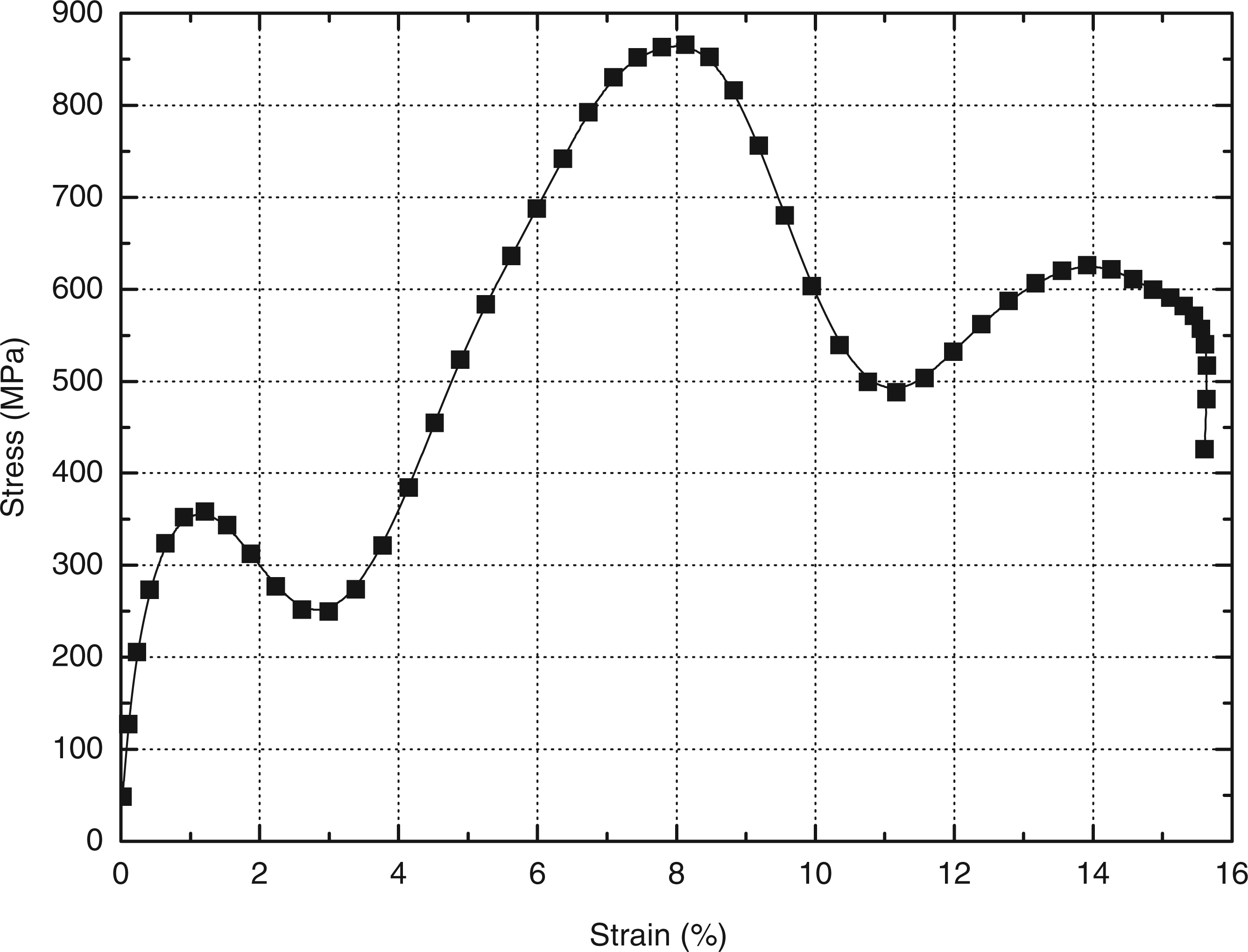
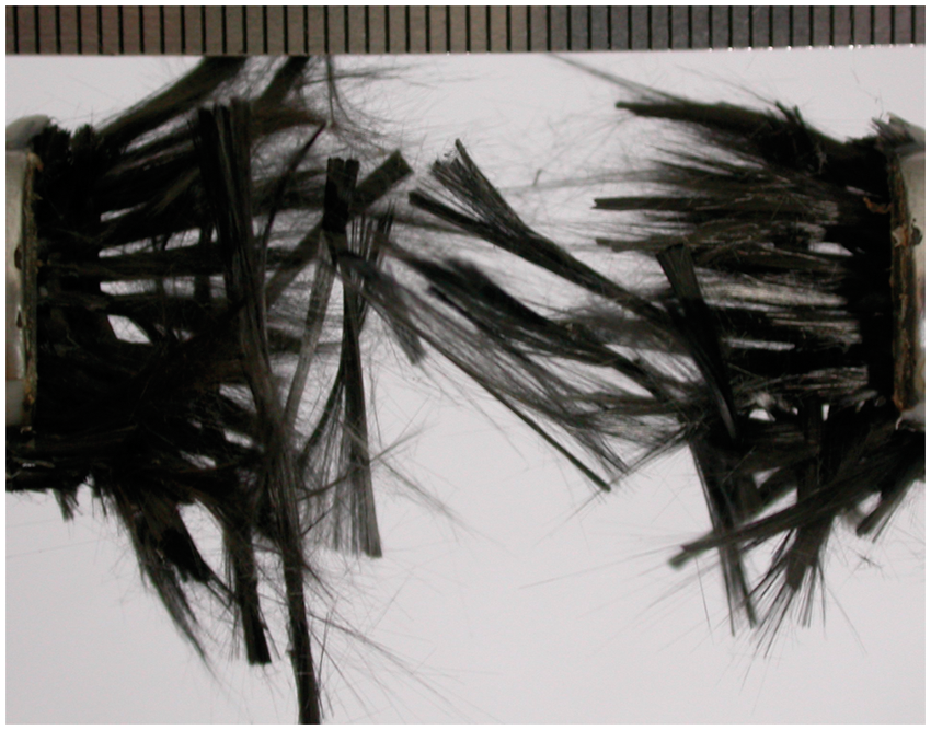
Figure 9 shows the typical signals of the input and output waves of 3DOWF under a strain rate of 2266/s. The stress–strain response of 3DOWF was calculated from equation (1) and is illustrated in Figure 10. The corresponding fracture morphology is shown in Figure 11. It can be observed that the tensile stiffness of 3DOWF exhibited two phases under high strain rates, with the elastic modulus in the second stage decreased. The first stress peak was lower than the second peak. The primary reason for the two-phase tensile stiffness phenomenon lay in the special architecture of 3DOWF. First, all the carbon filaments in the bundle were in different states, with some being straight or pre-stressed and others being wavy during weaving. The straight ones were the first to sustain the tensile loading when the transient stress wave was transmitted through the fabric. Besides, some defects (e.g. micro cracks, narrow necks) along the carbon filaments generated from the manufacturing process directly led to fiber breakage at a lower stress level. These straight fibers and those with flaws broke first when the stress wave was propagated. Second, 3DOWF was fabricated by four layers of weft yarns and three layers of warp yarns, as presented in Figure 1, and therefore different layers of weft yarn fractured at different times due to the various contact and interlacing conditions with the warp and the Z yarns. As the tensile stress wave was propagated along the weft yarns, it was partially reflected and partially transmitted to the warp and Z yarn systems at the interlacing points and contact areas. The warp and Z yarn systems deformed and moved, with some yarns being scattered or flying away, as shown in Figure 11. Given the multiscale and complicated contact and interlacing conditions among the three yarn systems, the stress wave propagation history in each yarn layer and the fracture morphologies were different. In particular, the weft yarn layers in the top and bottom were interlaced with the Z yarns and then contacted with the warp ones, while the two weft layers in the middle were only in contact with the warp and Z yarns. Thus, the reflection and transmission of the stress wave in the top and bottom weft yarn layers were much more intense than those in the middle. As a result, the four weft yarn layers would fracture at different times, which gave rise to the two stages in the strain–stress curves. In summary, the two-phase feature in the tensile stiffness of 3DOWF can be attributed to its particular architecture. Still, it is difficult to explain in detail during this transient process (less than 40 μs) without the aid of a high speed video camera.
Typical signals of input and output waves of 3DOWF under a strain rate of 2266/s. Strain–stress curve of 3DOWF at a strain rate of 2266/s. Fractograph of 3DOWF under a strain rate of 2266/s.
Comparison of tensile behaviors of 3DOWF under different strain rates
Figure 12 illustrates the stress–strain curves of 3DOWF under different strain rates, and the fracture morphologies are shown in Figure 13. It can be seen that the tensile fracture mechanism under quasi-static loading was quite different from that under the high strain rates. The reasons for such a difference can be interpreted from the stress wave propagation in the unique structure. When the specimen was stretched under quasi-static tension, there was sufficient time for the whole system to be uniformly stressed and only a small percentage of the load was transferred to the warp and the Z yarn systems. Just as shown in Figure 13(a), there was nearly no deformation or movement in the warp and the Z yarns. When the specimen was subjected to a strong impact wave of high strain rate, there was no time for the whole structure to be under a uniform stress state before some yarns fractured. Intense reflection and transmission of the stress wave occurred at the interlacing points and the contact areas of the three yarn systems. The weft yarns fractured instantly and the warp and the Z yarns were subjected to fast movement and deformation, damaging the whole structure completely, as displayed in Figure 13(b) to (e).
Stress–strain curve of 3DOWF under quasi-static and high strain rates. Tensile fracture morphologies of 3DOWF under different strain rates.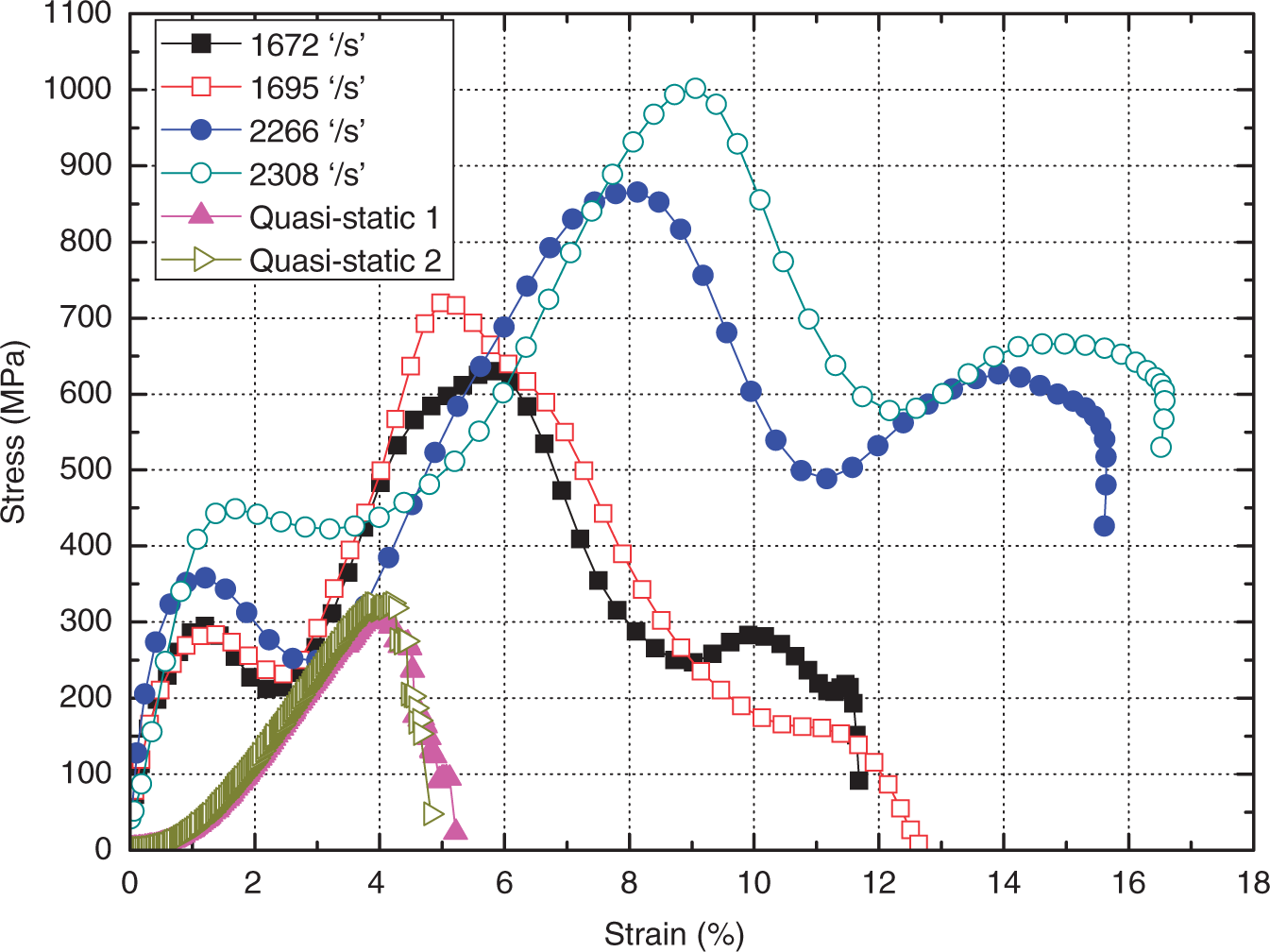

Tensile parameters of 3DOWF under different strain rates
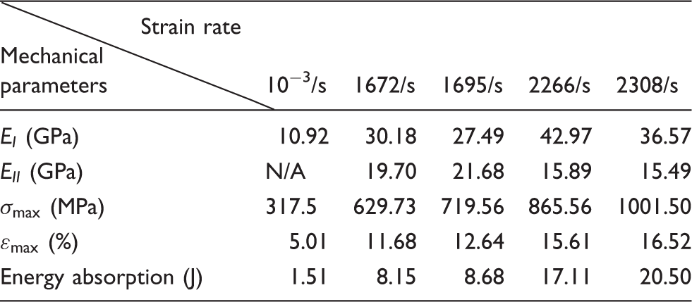
It has been reported that carbon fiber bundles are strain-rate insensitive21,22, but these experimental data prove that the tensile behavior of 3DOWF is strain-rate sensitive, i.e. the fiber yarns used were strain-rate insensitive, and thus the sensitivity must be from the geometric deformation. This can be attributed to the unique architecture of the woven fabric rather than to the mechanical performance of the fiber bundles. For woven architecture under impact tension, the stress wave will be transmitted and also reflected at the cross-points of the warp and the weft yarns. The Z yarns in the complex architecture will also withstand wave propagation and transmission along the warp and the weft yarns. However, all the yarns will be under an equilibrium state during quasi-static tension before the fabric rupture. Such different stress states will induce the strain-rate sensitivity of the 3DOWC sample, although the carbon fiber tows are insensitive to the strain rate.
Based on the strain-rate sensitivity, this novel woven structure can be used in impact protection applications, in which the energy absorption ability is of significant importance. The energy absorption of 3DOWF under different strain rates is illustrated in Figure 14 and Table 3. It was found that the specimen absorbed more energy under higher strain rates when being stretched to the same strain. However, lower (from 100/s to 1000/s) and higher (>2500/s) strain rates cannot be obtained due to restrictions of the SHTB system. Therefore, further research can be done on the basis of modifying the SHTB apparatus, such as adjusting the length and diameter of the bars and changing the bar material.
The energy absorption vs strain curves of the 3DOWF under various strain rates.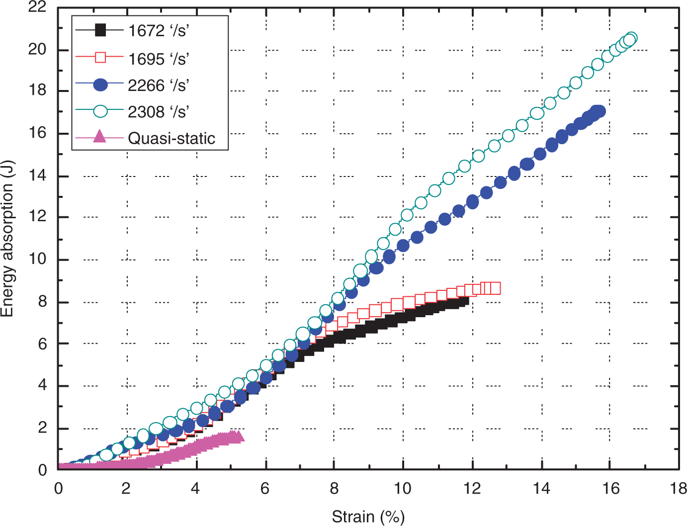
Meso-scale finite element model (FEM)
FE modeling of the tensile response of 3DOWF under high strain rates was carried out in the commercially available software package ABAQUS®/Explicit (Version 6.10). The finite element analysis (FEA) in this work was achieved in the yarn level.
FE model
To simplify the FE model, the following assumptions were made:
The T300 3 K carbon yarn in 3DOWF was regarded as a homogeneous continuum with an elliptical cross-section. The surface of the yarn was assumed to be uniform and the interaction between the three yarn systems was taken into consideration by introducing penalty friction. All the yarns contacted compactly in the original state and there was no space around the interlacing points.
According to the cross-sectional photograph of 3DOWF in Figure 2, an elliptical section with a ratio (the major radius to the minor radius) of about three was set to the yarns. The precise size of the cross-section of each yarn system can be calculated in terms of the specifications of 3DOWF listed in Table 2. Then a meso-geometric model of the specimen can be created and assembled in ABAQUS/CAE.
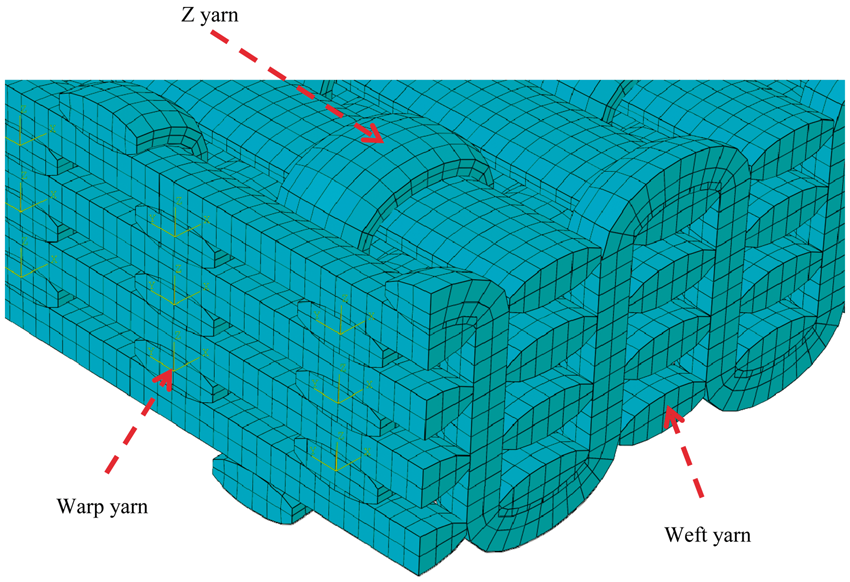
The whole geometric model was meshed with eight-node hexahedral reduced integration elements (C3D8R). Two ends (about 0.02 mm) of the ellipse section mentioned above were cut off to prevent numerical singularity at the elements with sharp angles, as indicated in Figure 15. The entire meshed model of 3DOWF is shown in Figure 16. The T300 3 K carbon fiber tow was defined as a transversely isotropic material, the mechanical parameters of which are listed in Table 4. Maximum stress failure criteria were introduced to determine element deletion. Also, self-contact was created between each of the two yarn systems to simulate interaction during the impact tensile process, and the penalty friction coefficient was set at 0.2. During the FE analysis, the geometric nonlinearity of 3DOWF was incorporated into the FE model to predict precisely the large deformation of the fabric.
Geometrical model of yarns and the mesh scheme. Geometrical and meshed model of the entire structure of 3DOWF. Loading condition of FEM model. Elastic parameters of T300 3 K carbon fiber tow in the FE model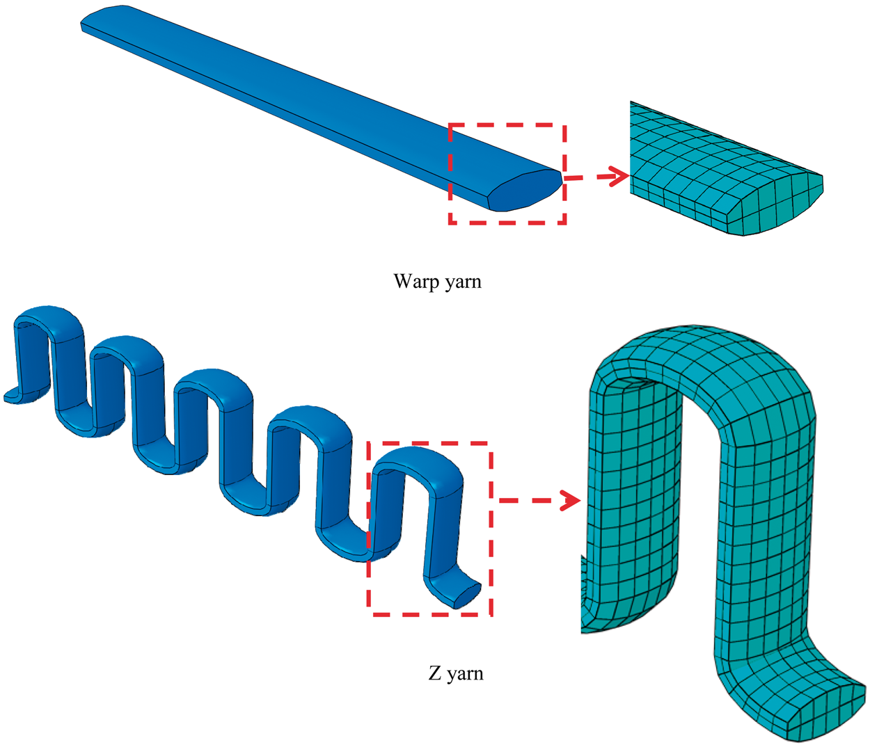
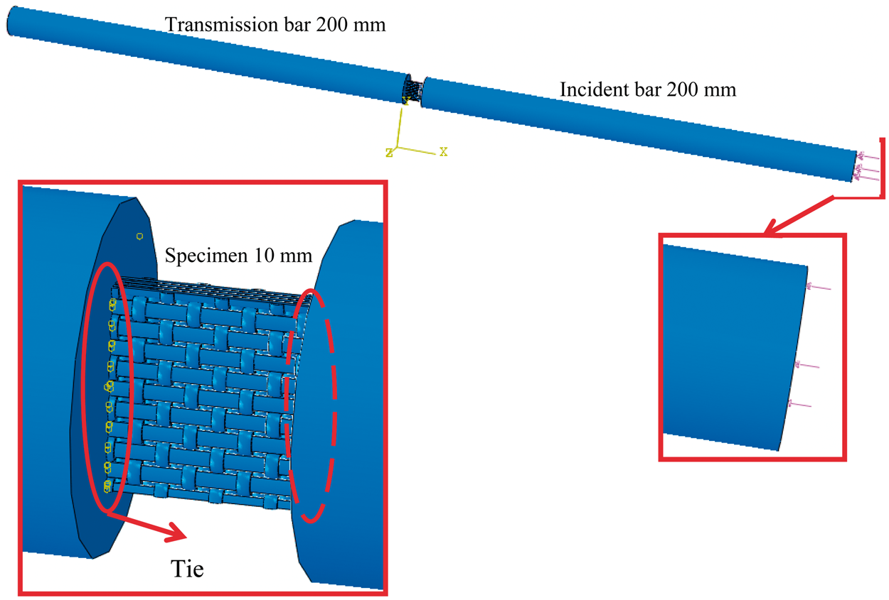

Furthermore, as can be seen from Figure17, incident and transmission bars of 200 mm were established to reduce the calculation time. The effective tensile waves extracted from the real impact tests, illustrated in Figure 18, were applied to the free end of the incident bar.
Effective tensile stress waves applied to the FE model.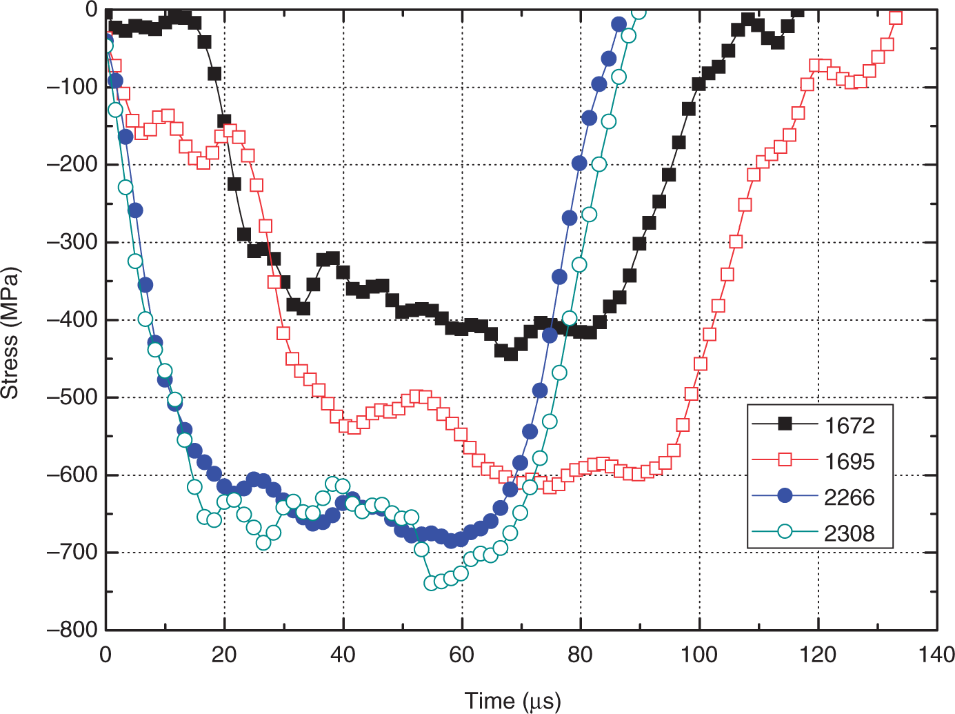
Results of FE model under a strain rate of 2266/s
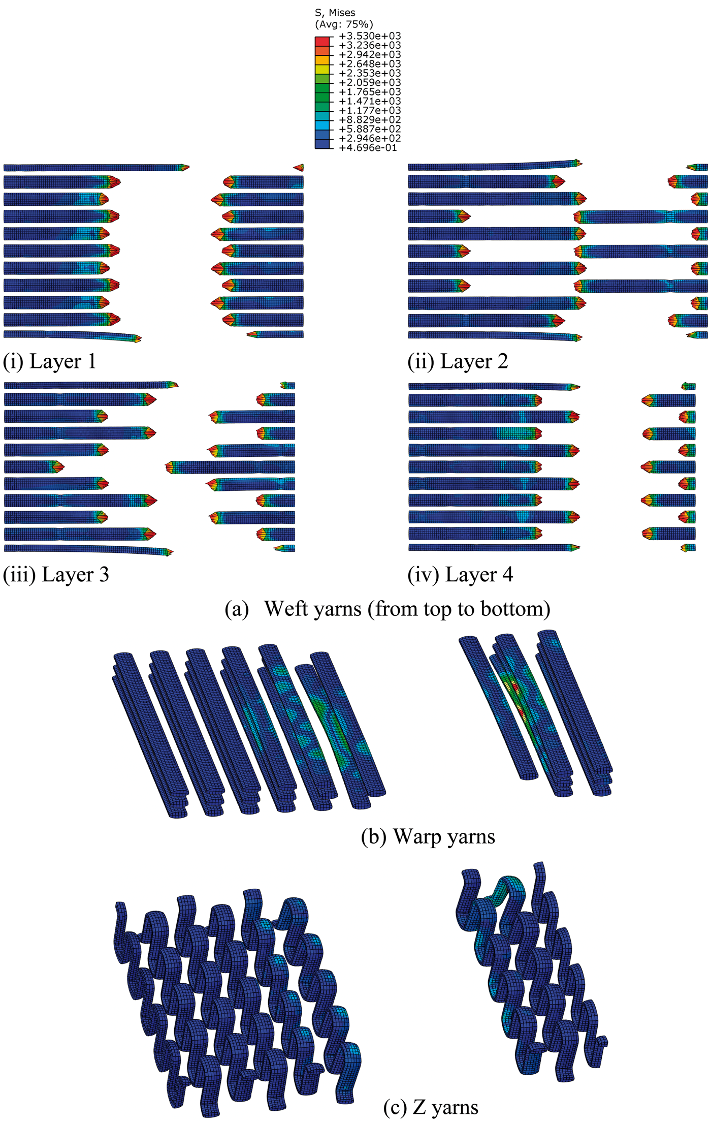
The FE model was performed in ABAQUS /Explicit. The deformation evolution and contour of the von Mises stress (S11) of the 3DOWF under a strain rate of 2266/s is exhibited in Figure 19, and the deformation of each yarn layer of the three yarn systems is shown in Figure 20.
Deformation history and contour plots in von Mises stress (S11) of 3DOWF under a strain rate of 2266/s. Fractographs of the three yarn systems under a strain rate of 2266/s.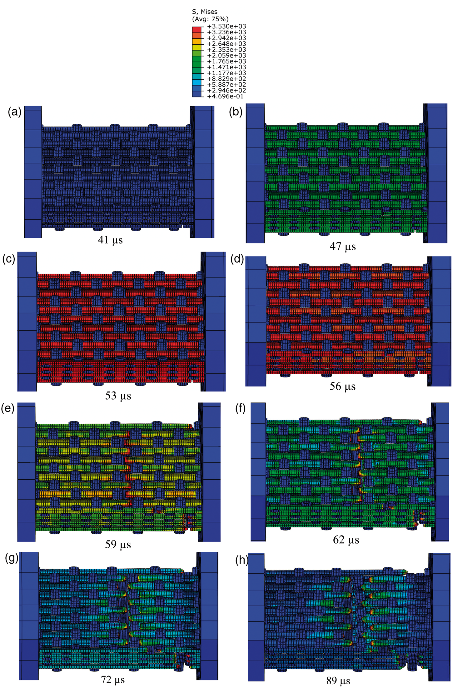
The load–displacement curve of the 3DOWF under a strain rate of 2266s−1 was obtained from the FE model, as shown in Figure 21. It was found that the maximum force attained in the FE model showed a good agreement with the experimental value. The elastic modulus indicated in the FE model just fell between the elastic modulus of the two stages in the experimental results. However, the FE model did not reveal the two-phase tensile stiffness phenomenon that was observed in the experimental results. This was because the FE analysis was conducted at the yarn level instead of the fiber scale, i.e. all fibers in the yarn were regarded as a homogeneous continuum. The defects or weak links generated in the fibers during the manufacturing process were also ignored. The tensile strength of the T300 3 K carbon fiber tow was not constant, but followed a strength distribution, for instance the Weibull Distribution. All the yarn systems were idealized as straight parts with no crimps or straight parts connected by arc ones, in which the contact conditions were restricted, unlike in the real fabric.
Comparison in load displacement curve of 3DOWF between the experimental results and the FE model under a strain rate of 2266/s.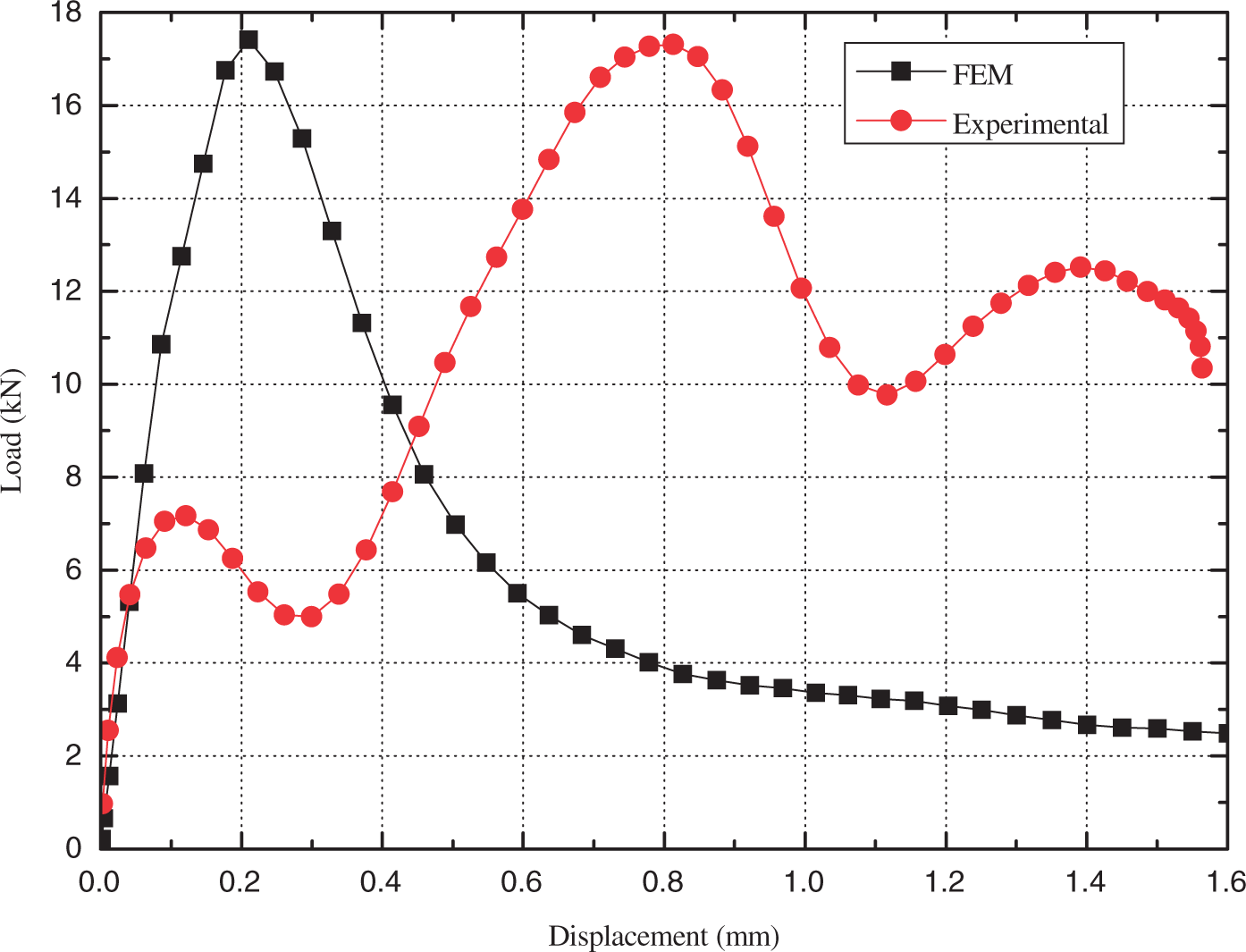
Comparison between the FE model and the experimental results
The comparison between the numerical and experimental results under different strain rates is displayed in Figure 22. As can be seen from the FE results, 3DOWF was highly strain-rate sensitive; the elastic modulus and the maximum force both increased with increases of the strain rate. However, the effect of the unique architecture of 3DOWF on its strain-rate sensitivity could not be interpreted by the FE analysis due to the idealization of the geometric model.
Comparison of the load displacement curves of 3DOWF under different strain rates between the FEM and the experimental results.
The fracture morphologies of 3DOWF under various strain rates were also obtained and are presented in the right column of Figure 23. Compared with the experimental fracture photographs, the deformation of the warp and Z yarns in the FE model was much smaller. The main reason for the difference was the complicated reflection and transmission of the stress wave in the real fabric structure. Owing to the complexity of the intertangling, interlacing and contacting conditions between the fibers and the yarns, the interaction between the three yarn systems could not be represented simply by self-contact in the FE model.
Comparisons of fractographs of 3DOWF between the experimental results and the FE model.
It is suggested that the establishment of an FE model on a filament scale could provide a deeper understanding of the tensile mechanism of 3DOWF under higher strain rates. The fiber trajectory in the fabric should agree with that in real fabric structure. The strength distribution of the T300 3 K carbon fiber tow can be introduced by a user subroutine. The lateral interaction between the yarn systems and the filaments should be taken into consideration. Another solution is to introduce a multiscale microstructure model ranging from the single fiber to the whole fabric.
Conclusions
This paper is the first attempt to investigate the tensile behaviors of 3-D woven fabric, named as 3-orthogonal woven fabric, under high strain rates. The tensile behaviors of the 3-D woven fabric were obtained under high strain rates (up to 2308/s) and compared with those of the quasi-static state (0.003/s), both from experiments and numerical calculations. In the experiments, the tensile behaviors of the 3-D woven fabric were tested under a high strain-rate state using an SHTB apparatus. The tensile failure morphologies were observed to analyze the failure mechanisms. In the numerical approach, a microstructure geometric model at the yarn level was established to find the mechanisms of the strain-rate sensitivity. It is found that the 3-D woven fabric structure is highly sensitive to the strain rate, even though the constituent materials (warp, weft and Z yarns) are not strain-rate sensitive. Through the observations from the experimental and the numerical simulations (FEA), this rate-sensitivity is attributed to stress-wave propagation, transmission and reflection in the cross-points among the warp yarns, weft yarns and Z yarns. The two-phase tensile modules of the 3-D woven fabric under a high strain rate tension were obtained experimentally. This interesting phenomenon may be novel and unique to the tensile behaviors of 3-D woven fabric and also be of benefit for impact energy absorption because of the non-simultaneous rupture of the fiber tows. Investigations of the tensile impact behaviors of 3-D woven fabric could be extended to characterize the tensile behaviors of 3-D woven composites under high strain rates. Furthermore, the tensile behaviors obtained from this investigation could be applied to an impact-damage tolerance design of 3-D woven fabric and composites because the tensile parameters of 3-D woven fabric are fundamental to both the woven fabrics and the woven composites.
Footnotes
Acknowledgements
The authors acknowledge the financial supports from the National Science Foundation of China (Grant Numbers 11072058 and 11272087). The financial supports from Foundation for the Author of National Excellent Doctoral Dissertation of PR China (FANEDD, No. 201056), Shanghai Rising-Star Program (11QH1400100) and the Fundamental Research Funds for the Central Universities of China are also gratefully acknowledged.
Funding
This work was supported by the Natural Science Foundation of China (NSFC) under the grant number of 11072058 and 11272087.