
Abstract
A series of ballistic tests on triaxial braided carbon/epoxy composites were described in Part I of this paper. In this part, numerical simulations were carried out to investigate the impact response, damage evolution, and penetration mechanisms of these composites. A continuum finite element model was developed to obtain the time history of the projectile velocity, displacement, penetration resistance force, and energy absorption during the impact process. By fitting the numerical data, the ballistic limit velocity can be obtained. Good agreements were achieved between numerical results and experimental results. Numerical predictions for ballistic tests of the composites indicate that, based on variations of damage mechanisms and failure features, the impact process can be subdivided into three stages, i.e. phase I – shock compression, phase II – bulge deformation, and phase III – penetration process, among which phase II consumes most of the projectile kinetic energy. The differences between a blade-like projectile and a cylindrical projectile in the impact process are also addressed in detail.
Many efforts have been made to investigate the ballistic response of high performance fiber-reinforced composites, including analytical studies, experimental investigations, and numerical simulations.1–3 It is observed that the kinetic energy of the projectile under ballistic impact is dissipated in the form of several mechanisms. The predominant energy absorption mechanisms of laminates under high velocity impact are: kinetic energy of moving cone formed on the distal side of the laminate, frictional energy absorbed during penetration, and energy absorption due to failure, such as shear plugging, tensile fiber failure of the primary yarns, elastic deformation of the secondary yarns, fiber debonding, fiber pull-out, matrix cracking (intralaminar), and interlaminar delamination.4–6
Numerical techniques have been widely used to predict the response behaviors and the failure mechanisms of composites due to transverse impact loading. Hayhurst et al. developed an approach combining conventional equation of state behavior with the constitutive model for anisotropic materials. 7 The proposed approach has recently been implemented in ANSYS/AUTODYN, and employed to solve ballistic impact problems on thin or thick composite laminated plates by both Silvaa et al. and Kumar et al.8,9 Her and Liang studied the behaviors of composite laminates and shell structures subjected to low velocity impact using LS-DYNA, 10 where the impact-induced damage including matrix cracking and delamination were predicted by the failure criteria suggested by Choi and Chang. 11 Hou et al. improved the Chang–Chang failure criteria and implemented it into LS-DYNA for laminated composite structures.12,13 This suggested, for the first time, that delamination is constrained by through-thickness compression stress, and good agreement with experimental results in damage predictions was found. The failure criteria were employed to predict the damage of a composite laminate under low velocity impact. 14 The impact-induced deformation and the damage of composite plates subjected to soft-body, high-velocity impacts were addressed by Nishikawa et al. 15 Sevkat et al. adopted a nonlinear-orthotropic damage model to study the damage in composite beams subject to ballistic impact. 16
The continuum damage mechanics (CDM) approach has been investigated by many researchers in recent years and its application to impact damage modeling has proved to be very efficient. The CDM approach has the advantages of predicting damage initiation in combination with the stress and/or strain failure criteria and predicting the failure progression when combined with the fracture mechanics approach by coupling the internal damage variables with the fracture energy. Recent works include those by Ladeveze and coauthors, who used a damage mechanics approach to describe matrix cracking and fiber/matrix debonding by introducing damage variables associated with the material stiffness reduction.17,18 Johnson et al. developed a CDM model for fabric-reinforced composites based on methods originally developed for unidirectional ply materials and implemented it into PAM-CRASH.19,20 Matzenmiller et al. developed a CDM model for unidirectional composites (MLT model). 21 Gower et al. investigated the ballistic response of laminated composite panels through numerical methods using the CDM model developed by Matzenmiller et al.21,22 Nandlall et al. employed a two-dimensional (2D) axisymmetric version of the CDM model which accounts for through-thickness damage modes to predict the ballistic limit of GRP laminates. 23 Williams et al. implemented a plane-stress CDM based model for composite materials in LS-DYNA,24,25 which proved to be a versatile tool for predicting damage progression in composite structures. Yen developed a general rate dependent progressive failure model for a fabric lamina using the CDM approach provided by Matzenmiller et al.,21,26 which can account for the experimentally observed nonlinear and rate dependent behaviors. The composite failure model has been integrated in LS-DYNA as MAT161/162 which has been used successfully in predicting energy absorption and damage by Chan et al., 27 Loikkanen and Powell, 28 Deka et al.,29,30 and Gama and Gillespie. 31
For triaxial braided composites, although micromechanical models have been employed to predict their mechanical properties and failure modes,32–34 they are not practical when studying their ballistic behavior. Simulations on impact behavior of triaxial braided composites are always based on simplifications of the fiber configuration. Xiao et al. simulated the braided composite tube axial crush using shell elements based on a composite damage constitutive model (MAT58) in LS-DYNA. 35 It was found that MAT58 could reproduce the softening behavior of the braided composite under monotonic compressive loading, but failed in subsequent unloading and tensile loading cycles. Based on the disadvantages observed, they developed an analog model and a coupled damage-plasticity constitutive model to improve the prediction of the tube crush.36,37 In addition to the continuum modeling method, Binienda and coworkers developed a simplified braiding through integration points model for triaxially braided composite.38,39 In this method, the unit cell of the braided composite is modeled as a series of shell elements, where each element is modeled as a laminated composite. By defining the integration points of shell elements, the layer sequence and angle can be assigned easily, and ballistic model can be performed with great efficiency. Although the research works mentioned above all employed shell elements to model the braided composites, those modeling methods could not reproduce the deflection and global deformation of the composite plate due to transverse impact, especially when the plate section is thick. The interaction between layers and delamination failure modes can not be simulated as well. Therefore, in the current paper, a layered composite model based on continuum mechanics using solid elements was developed to investigate the penetration process and delamination failure of triaxial braided composites.
As described in Part I of this paper, triaxial braided composites exhibited better ballistic resistance than the satin woven ones; thus numerical simulations were conducted for this type of composite. A finite element method based on the CDM model was used to predict the failure responses of triaxial braided carbon fiber/epoxy composite plates under the impact of projectiles with different shapes. The computational results were compared with the experimental ones to validate its effectiveness. Then the penetration mechanisms, energy absorptions, and damage propagations of the composites were analyzed in order to gain insight into the damage mechanisms and impact resistance of the composites. The differences between the impact processes and damage mechanisms caused by blade-like projectiles and cylindrical projectiles were also addressed.
Numerical modeling approach
Numerical model development
The commercial transient explicit code LS-DYNA was used to analyze perforation mechanisms, failure modes, and damage evaluations during high velocity projectile impact on triaxial braided composite target plates. Even though the fiber directions of triaxial braided composite are in the 0° direction and ±60° direction instead of along the 0° direction and 90° direction as usual for fabric laminates, it can still be simplified as an orthotropic continuum. Consequently, each lamina of the braided composite plate was represented as a homogenized continuum in our numerical model. The numerical simulations were conducted using the mechanical properties tested in the axial direction and the transverse direction.
As the braided layers are piled up in the same direction, the composite panel is symmetrical in plane. Quarter models were developed for the two configurations which have been tested experimentally, including cylindrical projectiles and blade-like projectiles, as shown in Figure 1, where each ply in the laminated panel was modeled as a separate entity with a tie-break interface used to model inter-ply delamination and contact. Both the projectiles and the composite plates were meshed using eight node brick elements with a single integration point. These 14 layer triaxial braided composite plates were modeled using 28 layers of brick elements with the size of 1.0 × 1.0 × 0.357 mm3 and the number 70,000 in total. Each layer had two elements through the thickness and represented one braid layer. The projectile was modeled with a mesh size of 0.5 × 0.5 × 0.5 mm3, using 19,440 solid elements for a cylindrical projectile and 8000 solid elements for a blade-like projectile. Refined projectile meshes comparable to the composite plate were employed to ensure effective contact between the plate and the blade during penetration.
Finite element model: global view (left); local view (right). (a) Cylindrical projectile and (b) Blade-like projectile.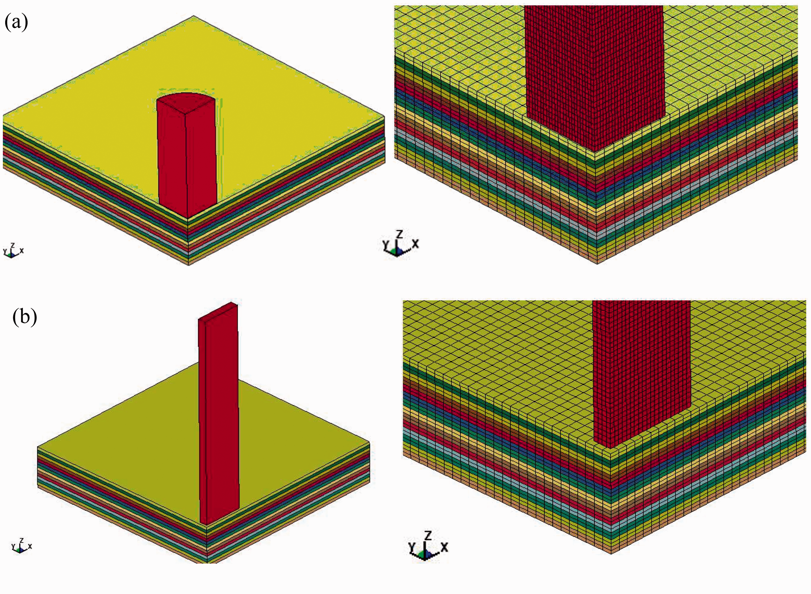
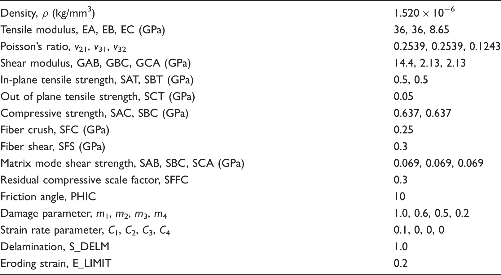
Material properties of the composite plate
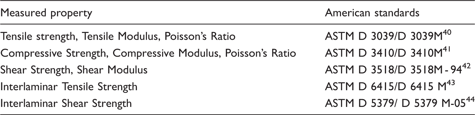
Test standards for composite material properties
Material model


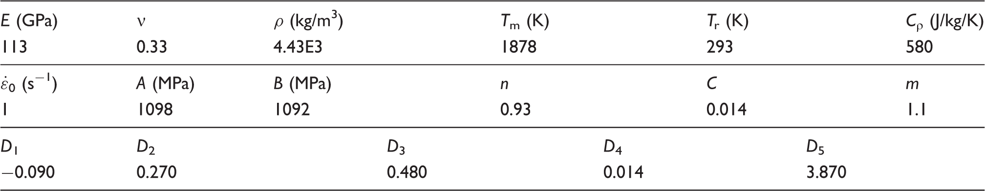
Material constants for Ti6Al4V
Failure criteria employed in this paper

During high velocity impact, high strain rate and high pressure conditions occur in the impact area. Gilata et al. and Hosur et al. reported in their studies that carbon/epoxy composites exhibit significant rate sensitivity.47,48 The effect of the strain rate on the ply strength is then modeled by strain rate dependent functions expressed as
Numerical results and discussion
Impact tests on triaxial braided carbon/epoxy composite were performed with projectiles of two different geometries. The cylindrical projectile impact was conducted as a baseline to investigate the penetration mechanisms while the blade-like projectile impact was used to evaluate the influence of blade geometry on the impact responses for applications in aero-engine fan containment systems. Simulations were conducted in the impact velocity range 50 m/s < Vi < 400 m/s. The velocity was chosen for two reasons. Firstly, the impact velocity in the experimental test was below the ballistic limit due to the limitation of test device. With numerical tools, the penetration mechanisms with impact velocity above the ballistic limit can be investigated. Secondly, the blade velocity in real aero-engine is always in the range of 200–400 m/s. Thus the highest impact velocity was set as 400 m/s.
Model validation with ballistic experiments
Numerical calculations were conducted and the residual projectile velocities derived (Figure 2). The computational time for each impact velocity was chosen such that the projectile velocity becomes constant after rebound or complete penetration. The cylindrical projectile is found to rebound at an impact velocity of 210 m/s, and perforate at 225 m/s. Similarly, the blade-like projectile rebounds at a velocity of 197.8 m/s and perforates at 220 m/s. Experimental studies have shown that the residual velocity of composite can be fitted with the Lambert equation
36
Time history of projectile velocity predicted by numerical methods. (a) Cylindrical projectile and (b) Blade-like projectile.
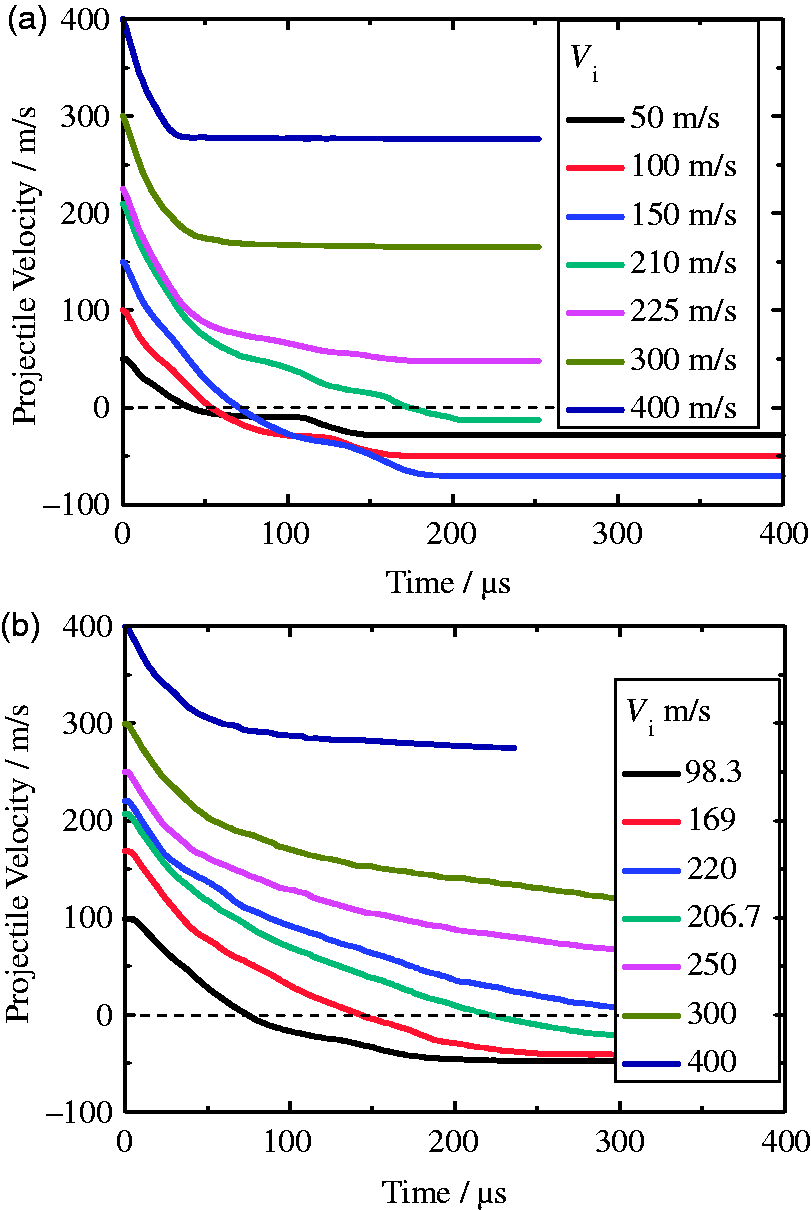
The ballistic limit velocity is obtained for triaxial braided composites by fitting the residual velocity, as shown in Figure 3, which is 210.5 m/s for cylindrical projectiles and 220.7 m/s for blade-like projectiles, respectively.
Fitting curve of residual velocity with respect to impact velocity. (a) Cylindrical projectile and (b) Blade-like projectile.
Figure 4 shows the failure features predicted by the finite element model compared with those in the tests. The composite specimen was not perforated by a cylindrical projectile with an initial velocity of 195 m/s in the test. After impact, a dent of 16 mm diameter was observed in the impact surface of the plate, and there were local fiber fracture damages in the back surface. The bulge region had a diameter of about 29 mm. The numerical results show almost the same failure modes, with a dent of 17 mm diameter in the impact surface and the bulge region of 32 mm in the distal surface. Elements in the distal surface failed and were deleted due to tension, corresponding to the fiber breakage in the experiment. The comparisons for the blade-like projectile with initial velocity of 197.8 m/s are also illustrated in Figure 4(b). From experiment results, a rectangular hole with a width of 25 mm, and ellipse bulge region with the long axis of about 40 mm can be observed. Numerical results display similar failure shapes and dimensions, with a 22 mm wide rectangular hole in the impact surface, and an ellipse bulge region with the long axis of about 34 mm. As the ballistic limit and failure features are predicted correctly, the finite element model proposed above can then be employed further.
Comparison of failure features of between experimental results and numerical predictions. (a) Cylindrical projectile, Vi = 195 m/s and (b) Blade-like projectile, Vi = 197.8 m/s.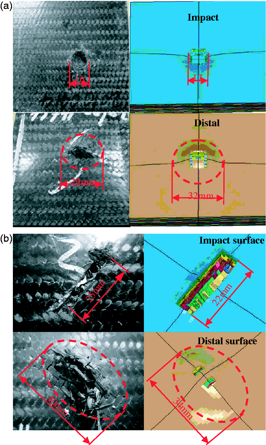
Predictions on ballistic damage and penetration of cylindrical projectiles
Impact results near ballistic limit
The penetration process of the cylindrical projectile with initial velocity of 195 m/s is described in detail as it is representative and close to the ballistic limit. The variations of penetration resistance force and energy with respect to time are presented in Figures 5 and 6, respectively. It can be seen that the impact process can be divided into three stages according to the interaction force, i.e. phase I – shock compression (0–8 μs), phase II – bulge deformation (8–34 μs) and phase III – penetration (>34 μs). It is observed that the variation trend is quite different during the three phases.
Variations of the penetration resistance force and the displacement of the projectile with respect to time, cylindrical projectile, Vi = 195 m/s. Variations of energy with respect to time, cylindrical projectile, Vi = 195 m/s, where Ekc and Eic denote kinetic energy and internal energy of case respectively, Ekb and Eib denote kinetic energy and internal energy of the blade.
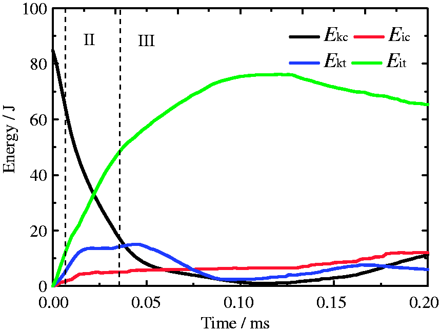
During phase I, there is a quick rise of the penetration resistance force in the beginning of the force–time curve until reaching to a maximum level (75 kN). The projectile velocity decreases sharply while the projectile displacement increases at a high rate. The projectile and target plate achieve complete contact and momentum transfer. The target below the projectile gains momentum and starts moving together with the projectile while the projectile undergoes deformations and also gains internal energy. The interaction process between the projectile and the target plate consumes about one-third of the total kinetic energy of the projectile, most of which is transformed into the internal energy of the target plate.
In phase II, the resistance force decreases quickly in the force–time curve to another peak value (42 kN). As the resistance force keeps at a relatively high level in this stage, the displacement increases with a high rate, while the projectile velocity decreases quickly. As the main features is the bulge deformation of the plate in phase II, the internal energy of the target plate increases substantially due to the tension of fiber, to which more than a half of the total kinetic energy is transferred.
During phase III, there is an obvious decrease in the resistance force and then it remains at a low level. Consequently, the projectile velocity decreases slowly while the displacement increases at a small rate until reaches to the maximum value. The oscillation of the resistance force is mainly due to the free vibration of the target plate. The projectile is rebounded as soon as its velocity decreases to zero and then part of the internal energy of the target plate is transformed into the kinetic energy of the projectile. Thus during phase III, the internal energy of the target plate increases for another quarter of the total energy, and then decrease about one-eighth in the end due to rebound of the projectile.
For cylindrical projectiles, phase II is the most important stage for energy absorption, although it lasts for about a tenth of the total impact time – a short time. As the main feature in phase II is bulge deformation, it can be concluded that the tension of fiber caused by the deformation of the composite plate is the main energy absorption modes.
Figures 7 to 9 show the strain wave propagation and the interlaminar delamination damage evolution of the triaxial braided composite.
Longitudinal strain wave propagation, cylindrical projectile, Vi = 195 m/s. (a) Phase I – shock compression (ɛx, −0.001–0.001), (b) Phase II – bulge deformation (ɛx, −0.01–0.01) and (c) Phase III – penetration (ɛx, −0.01–0.01). Through-thickness strain wave propagation in phase I, cylindrical projectile, Vi = 195 m/s (ɛz, −0.02–0.02). Delamination evolution mechanism, cylindrical projectile, Vi = 195 m/s. Blue color represents intact material, and red color represents delamination damage. (a) Phase I – shock compression and (b) Phase II – bulge deformation.
During phase I, as soon as the projectile comes into contact with the composite plate, the material of the plate under the projectile undergoes a shock compression and develops a shock front. When the projectile–composite contact has been established, a compressive strain wave front emerges and then propagates from the impact sites in all directions. A spherical compressive longitudinal strain wave propagates along the axial direction, and reaches the boundary at time 8 μs, as shown in Figure 7(a). The compressive through-thickness strain wave propagates to the back surface, and it is then reflected back as a tensile stain wave. The incoming compressive strain wave and the reflected tensile strain wave cancels each other out, which results in a shrinkage in the compressive area, as shown in Figure 8. In phase I, the maximum amplitude of the longitudinal strain wave is small (−0.001 < ɛx < 0.001) compared to the through-thickness strain wave (−0.02 < ɛz < 0.02). The initiation of the interlaminar delamination damage occurs along the projectile perimeter due to the shear plugging strain and the through-thickness compressive strain at time 2 μs. The delamination damage develops towards the back surface and reaches all of the predefined delamination interfaces at time 8 μs (Figure 9(a)). It can be concluded from the observations in phase I that the major events are the through-thickness strain wave propagation, crush failure in the impact surface, and initiation of delamination.
During phase II, as the projectile keeps moving forward, the material in the adjacent area begins to flow towards the impact sites and then moves together with the projectile. The tensile strain wave generates as the composite layer is stretched below the projectile, which propagates towards the boundaries with higher strain values (−0.01 < ɛx < 0.01). The compressive axial strain wave propagates in the thickness direction along the perimeter of the cylindrical projectile. The target plate below the projectile undergoes severe tensile action especially for the layers in the distal surface, as shown in Figure 7(b). The interlaminar delamination damage continues to develop along the interfaces of layers (Figure 9(b)). For phase II, longitudinal strain propagation and bulge deformation are the major events. The bulge deformation develops and extends without fiber fracture in the back surface. As the braided composite is ductile and flexible, the composite panel can undergo large local deformation, which helps to capture the projectile and absorb the projectile kinetic energy effectively.
In phase III, the penetration process, as the penetrating depth increases, the tensile damage in the area below the projectile in the back surface finally reaches the tensile/shear failure criteria defined in the constitutive model. The elements are deleted when fails, corresponding to the fiber fracture in the tests (Figure 7(c)). The interlaminar delamination area extends along the predefined interfaces. During phase III, tension failures in the distal surface, shear/compression failures along the projectile perimeter, and delamination failures are the dominant damage mechanisms.
Impact results above ballistic limit
By employing the validated finite element model, numerical prediction can be conducted for perforated cases at higher impact velocity, which is a great advantage of numerical methods-easy accessibility while low cost. Take the case with impact velocity of 300 m/s as an example for analysis. The time history of penetration resistance force is presented in Figure 10. According to the variation of the resistance force, the impact process can also be divided into three stages: a shock compression phase (0–6 μs); bulge deformation phase (6–30 μs); and penetration phase (>30 μs). The penetration resistance force increases to a maximum value of 90.8 kN quickly in phase I and decreases rapidly to a medium level of 29.2 kN during phase II. The maximum resistance force increases with the increase of impact velocity. Phase II, bulge deformation, absorbs a significant portion of the projectile kinetic energy, while phase I and phase III absorb limited kinetic energy. The projectile kinetic energy is consumed mainly in the bulge deformation phase, which is the same with the unperforated case analyzed before.
Penetration resistance force of triaxial braided composite in perforated cases, cylindrical projectile.
As shown in Figure 11, the strain wave propagation pattern damage mechanism is similar to the unperforated cases during phase I and phase II. As the projectile keeps moving forward, the elements in the back surface undergo great tensile damages and the failed ones are deleted as soon as the tension/shear criteria is satisfied. The projectile finally passes through the target plate with the increase of failed layers which are pushed away along the impact direction, as has been observed in the tests.
Longitudinal strain wave propagation (ɛx, −0.01–0.01), cylindrical projectile, Vi = 195 m/s. (a) Phase II – bulge deformation and (b) Phase III – penetration.
Prediction of ballistic damage and penetration of blade-like projectiles
Numerical calculations were also carried out for the response of the triaxial braided composites impacted with blade-like projectiles. Similar to the cylindrical projectile, the impact process with a blade-like projectile can also be divided into the three same stages. The time histories of penetration resistance force and projectile displacement were also calculated for blade-like projectiles, as shown in Figure 12. The penetration resistance force rises quickly to a maximum value of 46.3 kN in phase I, and decreases to a medium value of 20.2 kN in phase II. The variation trends are similar to cylindrical projectile cases, except that the maximum value is smaller due to a reduced contact area. The displacement of the blade-like projectile increases continually with a slow rate during the penetration phase, indicating that the projectile keeps penetrating the target. This is different from the cylindrical projectile impact case, in which the displacement decreases quickly due to rebound.
Variation of penetration resistance force and projectile displacement, blade-like projectile, Vi = 197.8 m/s.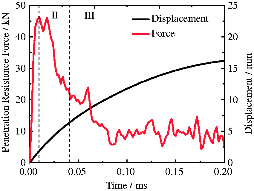
Figure 13 illustrates that the kinetic energy of the blade-like projectile decreases quickly in the early two phases, and decreases slowly during phase III. The projectile kinetic energy is about one-sixth consumed in the shock compression phase. Phase II significantly consumes half of the projectile kinetic energy. The penetration phase consumes another third of the kinetic energy. As the impact area of the blade-like projectile is smaller than that of the cylindrical projectile, the bulge deformation area decreases as well as the energy absorbed due to bulge deformation. In phase III, shear plugging failure, delamination failure, together with tension failure are the main energy absorption mechanisms. It can be concluded that, for blade-like projectiles, phase II and phase III are both important stages for energy absorption.
Energy absorption mechanism, blade-like projectile, Vi = 197.8 m/s.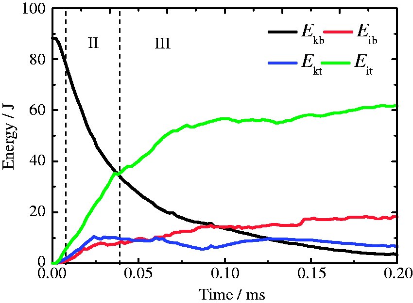
The strain wave propagation and delamination damage evolution mechanism in each phase are all described in Figures 14 to 16. The strain wave propagation and delamination evolution pattern during phase I and II are similar to cylindrical projectile impact cases while the penetration phase is quite different. The blade-like projectile is slender and not axisymmetric as cylindrical projectile does, therefore the strain wave propagates faster along the length direction than the width direction, as illustrated in Figure 14(a), which caused the elliptic bulge deformation region, as has been mentioned in the analytical model.
50
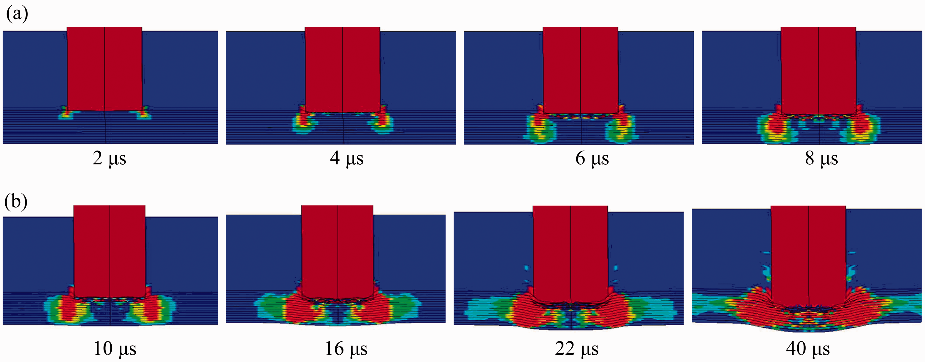
The delamination emerges along the section edge and propagates towards the back surface (Figure 16(a)). As shown in Figure 15, the through-thickness strain wave propagates in the rectangular area below the blade-like projectile. In phase II, the compressive axial strain wave propagates in the thickness direction along the section edge of the blade and the area below the blade undergoes tensile action (Figure 14(b)). Meanwhile the delamination damage extends along the interface between layers (Figure 16(b)). In phase III, the blade-like projectile penetrates into the target plate in the impact surface due to shear plugging failure. It is observed that at time 60 μs, the blade-like projectile has penetrated into the fourth layer, meanwhile the remaining three layers in the distal surface fail due to tension. The blade-like projectile has penetrated into seventh layer at time 120 μs and into the ninth layer at time 160 μs (Figure 14(c)). The layers in the distal surface fail due to tension, corresponding to the fiber fracture observed in test. The blade is rebounded even though it has penetrated into the target and caused failure in the distal surface.
Axial strain wave (ɛx) propagation, blade-like projectile, Vi = 197.8 m/s. (a) Phase I – shock compression (ɛx, −0.001–0.001), (b) Phase II – bulge deformation (ɛx, −0.01–0.01) and (c) Phase III – penetration (ɛx, −0.01–0.01). Through-thickness strain wave propagation in phase I, blade-like projectile, Vi = 197.8 m/s (ɛz, −0.02–0.02). Delamination evolution mechanism, blade-like projectile, Vi = 197.8 m/s. Blue color represents intact material, and red color represents delamination damage. (a) Phase I – shock compression and (b) Phase II – bulge deformation.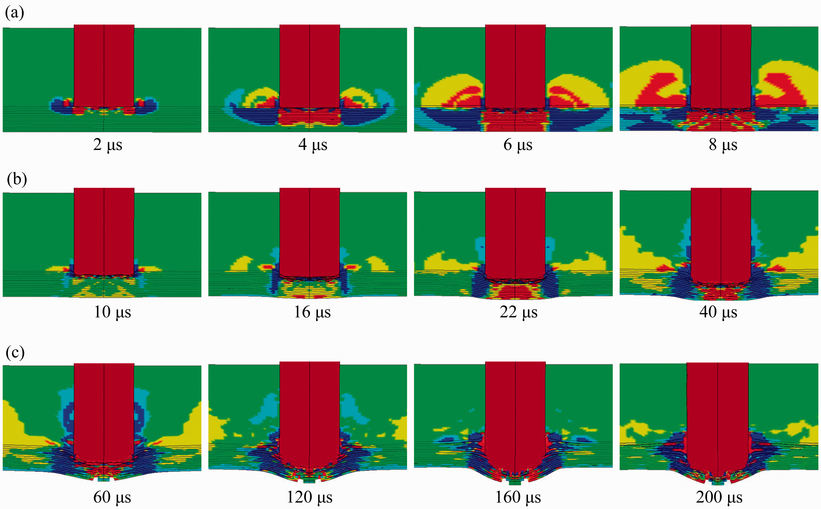

Conclusions
Numerical simulations were carried out to investigate the damage evolutions and penetration processes of triaxial braided carbon fiber/epoxy composite plates impacted by high speed cylindrical or blade-like projectiles. Finite element models based on continuum mechanics were employed to predict the time history of the penetration resistance force, energy absorption, and damage evolution of the composite during impact process. It is concluded that:
Based on the differences of damage mechanisms, the impact process can be divided into three stages: phase I – shock compression, phase II – bulge deformation, and phase III – penetration process. For the shock compression phase, through-thickness stress wave propagation, crush failure in the impact surface, and initiation of delamination are the major events, while longitudinal strain propagation and bulge deformation are major events for the bulge deformation phase. Tension failure in the back surface, compression/shear failure along the projectile perimeter, and delamination failure are dominant failure mechanisms in the penetration phase. Good agreements with experimental results are found in the damage areas and failure modes. Bulge deformation consumes most of the kinetic energy both in the cylindrical projectile and the blade-like projectile impact cases, which reveals that the deformation of the composite plate and the tension of the carbon fibers are effective energy absorption modes. It also demonstrates that the carbon fiber triaxial braided composite plate has good ballistic performance due to its ductility and deformability. For blade-like projectiles, phase III, the penetration phase, is also important for energy absorption, which is different from that in the cylindrical projectile impact case, because it keeps penetrating into the composite panel due to larger shear plugging action.
Footnotes
Funding
This work was supported by the Research Fund for the Doctoral Program of Higher Education of China (grant 20120101110065), Zhejiang Provincial Natural Science Foundation of China (grant Y1090245), Aeronautical Foundation of China (grant 20095276009), and Opening Foundation of State Key laboratory of Explosion Science and Technology of China (grant KFJJ10-9 M).
Acknowledgements
The authors wish to thank Dr Xing Jun and Mr Wang Jin from National Key Laboratory of Advanced Composites, Beijing Institute of Aeronautical Materials, for their help and guidance during preparation of the specimens.