
Abstract
Kevlar fabrics are extensively used in ballistic protection and containment applications. This study presents an investigation of failure for Kevlar fabrics under their in-service deformation mode of transverse indentation using a homogenized continuum constitutive model. Quasi-static indentation tests performed on uniaxial and 45° off-axial Kevlar K706 coupons with and without an elastic foundation were used to investigate failure modes and mechanisms. Two failure modes were identified – yarn breakage and yarn sliding, depending on the configurations of the tests. A stress-based failure criterion in conjunction with the constitutive model was implemented in numerical simulations to predict load–displacement behavior and failure load with good accuracy for the uniaxial case where the failure was due to yarn breakage. For the 45° off-axial case, an estimation of onset of failure due to yarn sliding is achieved based on a yarn locking parameter. The deformed shape and load–displacement behavior for the combined indentation tests with the elastic foundation are accurately captured by the model. This approach provides a relatively simple, computationally efficient means to predict failure due to yarn-scale phenomenon using homogenized properties for the fabric.
Kevlar® fabrics have been used extensively in ballistic protection and containment applications. Their high strength, high yarn direction modulus, flexibility and low relative weight offer considerable advantages in many applications. The fundamental components in Kevlar are the fibers. They consist of highly oriented chain molecules or crystals along the fiber axis. These fibers are bundled together to form yarns that are woven to produce the fabric. Plain woven fabrics have two orthogonal yarn directions – warp and weft. The mechanism by which Kevlar fabric resists ballistic impact and dissipates energy has been widely studied.1,2 Many aspects, such as material properties, weave style, boundary conditions, number of layers of fabric, inter-yarn friction and the geometry, velocity and material of the projectile, have been found to affect ballistic performance. 1 The fabric dissipates the impact energy by transmitting the load away from the impact location owing to a steep strain gradient along the principal yarns caused by the constraint imposed on them by neighboring yarns. 2 Hence the phenomenon of yarn pull-out in fabrics shows a close correlation to its ballistic performance. Pan and Yoon 3 predicted the relationship of the maximum pull-out load and the embedded yarn length in a woven fabric. Kirkwood et al.4,5 developed an empirical model based on various factors such as fabric style, length of sample and transverse fabric tension to predict the energy required to pull-out a yarn from Kevlar fabric. The study also demonstrated that quasi-static pull-out results can be correlated quantitatively with yarn pull-out during ballistic impact. Dong and Sun 6 studied the yarn pull-out behavior for five different styles of plain woven Kevlar fabrics. It was found that fabrics with higher pull-out force performed better in impact tests. A two-dimensional (2D) finite element model (FEM) that incorporated several factors affecting yarn pull-out, such as fabric count, yarn size, yarn crimp, fiber modulus, fiber diameter, cross-yarn friction and parallel-fiber friction, was developed. A simple empirical formula to compute the yarn pull-out force as a function of these factors was also developed. It was shown that the yarn count had a fourth-order effect and fiber diameter had a second-order effect, while yarn crimp, cross-yarn friction and modulus had a linear effect on the pull-out force. The yarn pull-out force can also be increased by introducing additives to the weave structure of the ballistic fabric. Sinnppoo et al. 7 demonstrated that the incorporation of wool into the weave structure of ballistic fabric can restrict the lateral separation of the principal yarns, thereby increasing the number of yarns participating in energy dissipation during an impact. Dong et al. 8 showed that silica nano-particle impregnated Kevlar fabrics have better ballistic performance over their neat counterparts.
Many different approaches have been taken to analyze and model woven fabric material behavior. Although individual yarns exhibit rate-dependent, nonlinear elastic behavior in tension, the behavior of the fabric itself is complicated because of the interaction of the two distinct media of yarns. The fabric experiences large deformations under impact that cause changes in the relative yarn orientations. The shear resistance of the fabric is dependent on the friction between the yarns, which varies with yarn rotations until locking occurs. Thus, the fabric has a nonlinear shear response under large deformations. There is also some amount of interaction between the axial and shear properties of the fabric. Other factors, such as initial yarn orientations, specimen size and boundary conditions, also influence the mechanical behavior and failure locations and modes in plain woven fabrics. Numerical models for fabrics may be broadly classified into three categories: (a) models using simplified orthogonal pin-jointed bars to model yarns; (b) unit cell-based approaches or equivalent homogenized continuum models; and (c) detailed three-dimensional (3D) models incorporating individual yarns and weave patterns with contact definitions. The following are some of the important modeling approaches for fabrics in the literature. Abaqus/Explicit 9 provides an inbuilt anisotropic, nonlinear, phenomenological fabric material model. The model can be used with experimental stress–strain data in the warp and weft directions along with the shear response. The test data based model assumes that the axial and shear responses of the fabric are independent. The axial stress–strain data is obtained from uniaxial tension tests, while the shear response can be obtained either from 45° off-axis tension tests or picture frame tests (PFTs). Carbajal and Diehl 10 modeled woven fabrics with Rebar elements to represent orthogonal yarns in Abaqus/Explicit. They also used adaptive meshing to redefine elements under large deformations to retain mathematical consistency. General contact definitions were given between layers of fabric. This model was used to simulate the high-speed non-penetrative impact of a projectile on multiple layers of fabric with a body simulant backing. However, this approach is computationally very expensive. Lin et al. 11 developed a numerical to predict the shear force versus shear angle response of a plain woven fabric. The fabric was modeled at the yarn scale by assuming yarn behavior to be that of a 3D orthotropic solid. Frictional contacts were defined between yarns and a displacement difference periodic boundary condition was used to define interactions between unit cells. King et al. 12 developed a continuum constitutive model for woven fabrics in which the fabric yarn structural configuration is related to the macroscopic deformation through an energy minimization method. Through this method, the response at the meso-structural level to macroscopic loading or the effects of changes at the meso-structural level on the macroscopic response can be evaluated. However, the model can predict only quasi-static in-plane loading cases. Out-of-plane displacements or transverse shear responses cannot be predicted. Although the model does not incorporate any explicit failure criteria for modes, such as yarn breakage, unraveling of the weave or yarn pull-out, the model can be used to predict macroscopic loads at which yarn failure will initiate in loaded fabric strips. In a study by Grujicic et al., 13 a meso-scale unit cell was developed and its properties were used to model plain woven Kevlar 129 fabric as a continuum surface via a user-defined material (UMAT) subroutine in Abaqus. Ballistic impact simulation using this model was compared to a computationally costly simulation in which the individual yarns were modeled using 3D continuum elements and woven explicitly. The properties of a single unit cell were obtained from contact forces and shear response of a solid finite element model of the cross-yarns under various loading conditions. Element erosion and stiffness modifications are used to describe yarn breakage or partial loss of load-carrying ability. Dong et al. 8 and Dong and Sun 14 developed a constitutive model based on in-plane uniaxial and biaxial tension tests to characterize the nonlinear anisotropic properties of neat and nano-particle impregnated Kevlar fabrics. It was found that fabrics impregnated with nano-particles exhibit significant improvement in shear stiffness over their neat counterparts by increasing the friction between the yarns. As the fabric has high yarn direction stiffness but low in-plane shear resistance, although strains in yarn directions are small, large deformations occur due to relative rotation of yarns. This behavior is simplified by a homogenized continuum model that uses the incremental deformation approach together with a procedure akin to the classical laminated plate theory. The model captures the coupled nature of the axial and shear responses at large displacements. This constitutive model was implemented as a UMAT subroutine in Abaqus. Simulations for various in-plane loading conditions yielded good agreement with experimental results. A detailed description of this constitutive model is presented in the Appendix.
Although many methods have been proposed to predict failure in woven fabric-reinforced composites, very few studies that deal with prediction of failure of woven fabrics themselves under various loading conditions exist. In fabric-reinforced composites, the relative rotation of yarns is restricted by the matrix material. Thus, the evolution of mechanical properties of the fabric due to yarn rotations does not occur. Further, final failure of the composite is caused by breakage of yarns. However, many different failure modes exist for fabrics because of their flexibility and relative yarn motion. Lim et al. 15 proposed a viscoelastic and strain-rate sensitive criterion to predict failure in Twaron fabric subjected to ballistic impact. The dynamic properties of Twaron obtained experimentally are used to calibrate a three element spring-dashpot material model. 2D plane stress membrane elements are used to model the fabric while the projectile is assumed rigid. It was observed in experiments that as the strain rate increases, failure stress increases and the failure strain decreases. Thus, a strain-based failure criterion that accounts for variable strain rates was used. The model is used to predict the ballistic limit, residual projectile velocity and transverse deflection profile of the fabric with good accuracy. However, fabric behaviors such as inter-yarn friction and unraveling or fraying of yarns are not considered. Using the failure load per yarn as a criterion, King et al. 12 predicted the onset of failure for the simple uniaxial tension test of Kevlar S706 fabric. The only failure mechanism investigated in this case was yarn breakage. It was observed that the fabric failure due to yarn breakage was at about 4% nominal axial strain. The model predicts that the yarns closest to the free edges carry greater load and will fail first with yarn failure propagating inwards, which is consistent with experimental observations. However, failure in off-axis tests is more complex because of wrinkling and unraveling of the weave at large strains and cannot be predicted on the basis of failure load for individual yarns alone.
In the present study, firstly quasi-static indentation experiments were performed on K706 coupons to investigate the failure modes and mechanisms. Coupons with uniaxial and 45° off-axial yarn orientations were tested. Combined indentation tests were also performed with a deformable backing material. Next, a stress-based criterion was implemented for the uniaxial case in the numerical simulation based on the constitutive model previously developed. 8 The constitutive modeling approach is summarized in the Appendix. For the off-axis case, the onset of failure in simulation is predicted using relative yarn rotations. The simulation predicts the load–displacement behavior and deformed shape for the combined indentation tests with good accuracy. This approach provides a relatively simple, computationally efficient means to predict failure due to yarn-scale phenomenon using homogenized properties for the fabric.
Experimental methods
Product data for Kevlar K706 fabric from Hexcel Co
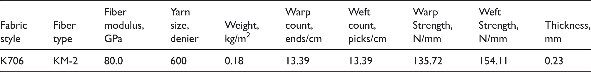
Figure 1 shows the schematic for the indentation test coupons. A rectangular strip of size 102 × 40 mm2 is cut from the fabric with the desired yarn orientation. Aluminum end tabs of 25.4 mm width were bonded using epoxy adhesive to the short edges of the specimen, leaving an effective fabric dimension of 51 × 40 mm2. The short edges are held fixed during testing, while the long edges are free. The specimen size and boundary conditions have been retained as the same across all the tests in this study. Uniaxial coupons tested were of two types. For the warp direction uniaxial coupon, the warp yarns are oriented parallel to the long edges running orthogonally between the fixed edges, while for the weft direction uniaxial coupon, the weft yarns were oriented in the same fashion. The yarn orientation angle, α, defined as the acute angle made by the warp-direction yarn with the short (40 mm) edge of the specimen, are 90° and 0°, respectively, for the warp and weft uniaxial coupons. For the 45° off-axial coupons (α = 45°), the warp and weft yarns are symmetrically oriented with respect to the boundaries. There are no yarns that bridge the gauge for this combination of weave style and specimen dimensions.
Diagram of uniaxial and off-axis indentation specimen.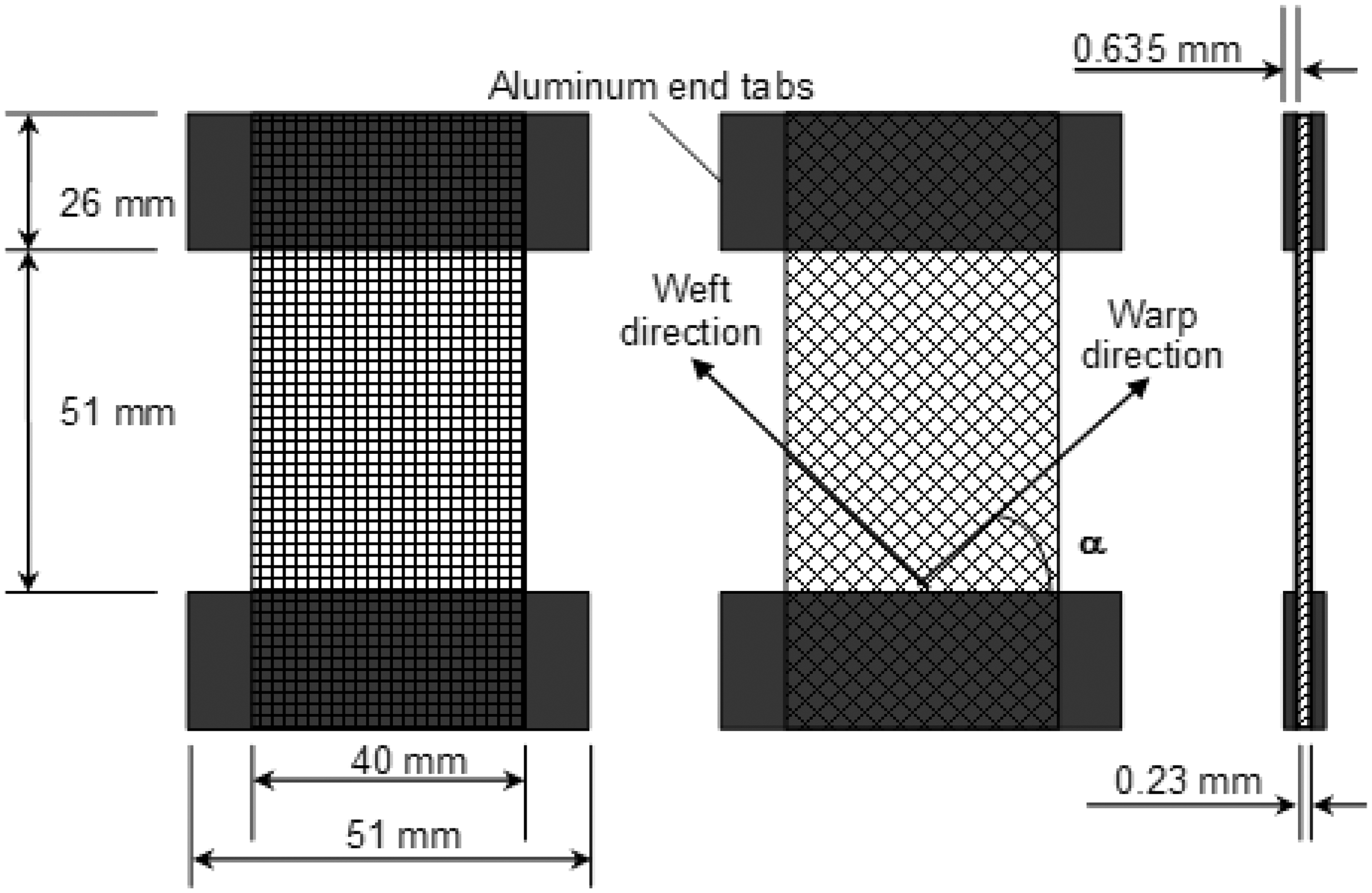
The details of the fixture used to hold the specimen in place during the indentation tests are shown in Figure 2. The fixture consists of a compression platen provided with an elevated, adjustable set of 3 mm thick aluminum plates. The tabbed ends of the specimen were held firmly in place without pre-tension between the upper and lower plates using screw clamps. A 12 mm diameter hemispherical steel indenter was used to indent the fabric (Figure 2). The indenter shank was held in the upper grips of a servo-hydraulic load-frame. The fixture, loaded with the specimen was aligned and held in the lower grips. The indenter tip was positioned so as to just touch the surface of the fabric at the center of the specimen. The test was done using displacement control with the lower actuator pushing the fabric against the indenter at a displacement rate of 0.14 mm/s. The maximum displacement level was set to 25.4 mm and a linear ramp function was used. Trials on specimens with various yarn orientations showed that final failure or onset of failure occurred well within this displacement range. Displacement output from the Linear Variable Differential Transformer (LVDT) and the indenter load output from the load cell were recorded using a LabView interface. Images were taken using a digital camera at discrete intervals to study the progress of the deformation.
Schematic experimental setup including a rubber foundation for combined indentation.
In order to obtain the combined indentation behavior of the fabric with a deformable backing material, indentation tests were also performed on 45° off-axial coupons with a 25.4 mm thick, 50.8 × 50.8 mm2 area square block of open-cell foam rubber. The total uniaxial compressive load–displacement behavior of the foam rubber piece was also obtained from compression tests on the rubber alone at a displacement rate of 0.14 mm/s up to a strain of 0.8.
Numerical modeling
Previously, a homogenized continuum model for Kevlar fabrics using the incremental deformation method in conjunction with a procedure resembling the classical laminated plate theory has been developed. 8 Uniaxial and off-axis tension tests were used to estimate the axial and shear moduli of the fabrics. A bilinear approximation was used to estimate the uniaxial properties. In order to incorporate the change in the axial moduli due to yarn rotations, a non-dimensional yarn spacing parameter is introduced in the approximation function. A nonlinear function that depends on this non-dimensional yarn spacing parameter and its limiting value was utilized to determine the shear properties. The warp and weft layers in the fabric are considered as two separate plies that occupy the same physical space in a composite laminate in the formulation. This approach thus takes into account the interaction between the axial and shear properties of the fabric under large shear deformations. Once the constitutive relations are established and the material parameters are determined from the test results, the model is implemented in the commercial FEM software Abaqus/Standard via a UMAT subroutine. Validation of the model was done by simulating various load cases. A detailed description of the formulation of the constitutive model and the material parameters for K706 is given in the Appendix. This model is used to incorporate the failure criterion for the indentation simulations.
The fabric was modeled as a 2D surface using plane stress shell elements (CPS4) and the indenter was modeled as an analytical rigid body. In the plane of the fabric, the direction parallel to the fixed edges is defined as the 1-direction and perpendicular direction is defined as the 2-direction. A frictionless contact definition was given between the indenter and the fabric. The short edges of the fabric were constrained in all translational degrees of freedom (DoFs), but the rotational DoFs were not constrained so as to replicate the highly flexible nature of the fabric. A prescribed displacement of 30 mm in the direction normal to the fabric surface was given to the indenter over the total time step with increments of 10–5 s. Figure 3(a) shows the FEM and boundary conditions.
Finite element model and boundary conditions for indentation simulations: (a) fabric alone; (b) fabric with rubber foundation.
The UMAT subroutine requires 10 input parameters. These are the initial yarn orientation angle (α), the pre- and post-uncrimping axial moduli in the warp and weft directions (
For the combined indentation of the fabric with a rubber backing material, the foundation is modeled as a set of nonlinear elastic spring elements. The fabric is meshed with a mesh density of 80 × 100 elements. Each node in the fabric mesh is tied to one end of the spring element. The other end of the spring element is tied to a corresponding node on a discrete rigid surface which is encastred. As the rubber foundation is discretized using 8000 spring elements in a parallel configuration, the nonlinear load–displacement data obtained from the compression test on rubber is factored by this number of spring elements for use as load–displacement input for the springs. Figure 3(b) shows the finite element model for the combined indentation simulation.
Discussion of results
Failure modes
For the indentation experimental configuration chosen, the following failure modes were observed. (i) Yarn breakage: this mode of failure occurred in the uniaxial indentation tests. The yarns running between the fixed edges directly under the indentor break at the contact location, leading to indenter penetration of the coupon. The loss of load-carrying capability occurs at a distinct load level in this mode as failure occurs when the tensile stresses in the yarns exceeds the failure stress (ii) Yarn sliding: the failure in the 45° off-axial case was exclusively due to yarn sliding at the corners of the specimen. As the deformation progresses, the increase in the relative yarn rotations lead to sliding of the warp or weft yarns over the shorter cross-yarns at the corners, leading to eventual separation of the coupons into two parts. The loss of load-carrying capability of the fabric is gradual because of the successive unraveling of each yarn in the weave. The onset of failure, however, occurs at a distinct load level. The yarn sliding is initiated when the yarn rotations have closed the inter-yarn spacing entirely and also laterally compressed the adjacent yarns.
Failure prediction for uniaxial case
As the fabric fails due to yarn breakage in the uniaxial indentation tests, a stress-based failure criterion is used to predict failure. Uniaxial tension tests were previously performed on K706.
8
The failure stress in the warp and weft directions for K706 in uniaxial tension are 580 and 740 MPa, respectively.
8
If the stress in the 2-direction (yarns running between fixed edges) exceeds the failure stress in the uniaxial tension test at any location in the fabric, then the fabric fails due to breakage of the axial yarns:


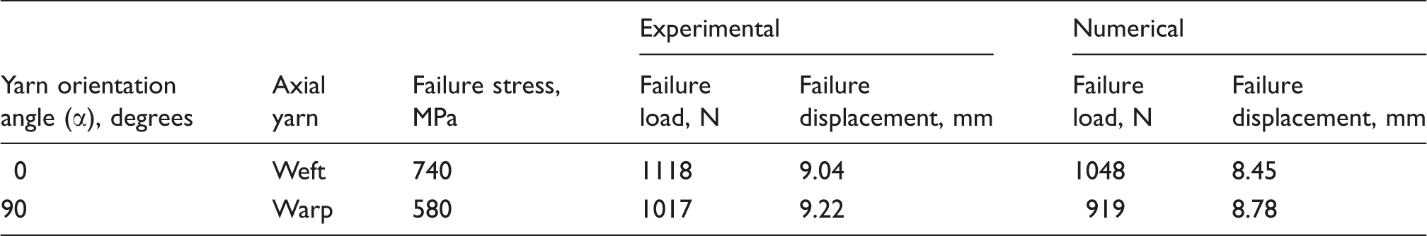
This condition was implemented in the numerical simulations. Figure 4 shows the comparison of the experimental and simulated load–displacement curves and failure load predictions for the warp and weft uniaxial indentation tests. The load–displacement curve has a nearly bilinear trend that is captured in the simulations. The initial low stiffness response is due to the uncrimping of the yarns, while the later high stiffness response is due to the yarn stretching. The simulations predict the load–displacement behavior of the fabric with good accuracy. At higher loads, the simulated curve is stiffer than the experimental curve, which may be due to slippage at the grips in the experiments. The experimental and predicted failure loads and displacements are summarized in Table 2. The predicted parameters are lower than the experimental parameters. The percentage error in the predicted parameters is less than 10%.
Comparison of experimental and simulated load–displacement curves with a yarn orientation angle of (a) α = 0° and (b) 90°. Uniaxial indentation tests: experimental and numerical failure loads and displacements
Estimation of onset of failure for the off-axial case
The experimental and simulated load–displacement curves for the 45° off-axial indentation tests are shown in Figure 5(a). The initial low stiffness response corresponds to the uncrimping and reduction of inter-yarn spacing due to rotation along the specimen diagonals. Once this compaction process starts to laterally compress adjacent yarns, the response becomes stiffer. As there are no direct yarns running between the fixed edges in the specimen, the failure mode is solely by yarn sliding at the corners. The onset of failure (at an indenter displacement of about 15 mm) occurs when the longer yarns slide over the shorter yarns at the corners of the fixed edges, leading to a progressive unraveling of the weave. The “sawtooth” response past the failure onset indicates the successive slippage of cross-yarns at the corners. After the maximum load value is reached, further unraveling causes the specimen to separate into two parts.
(a) Comparison of experimental and simulated load–displacement curves for K706 with a yarn orientation angle of α = 45° and (b) variation of warp (α) and weft (β) yarn orientation angles as a function of indenter displacement at failure location 1 (marked in Figure 3(a)) and at failure location 2 (marked in Figure 3(a)).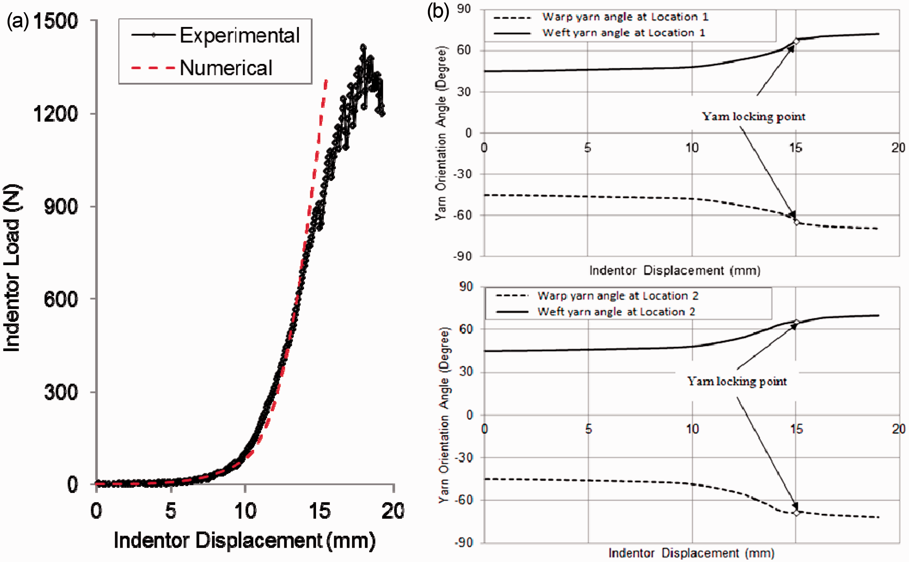
The constitutive model utilizes a non-dimensional yarn spacing parameter to model the highly nonlinear nature of the transverse modulus (see the Appendix). After the yarn rotations reach a critical locking value, further deformation is resisted by the transverse compression of the yarns. The relative yarn rotations are restricted once the yarn spacing reaches this locking value. In experiments, yarn sliding occurs subsequently. The simulated load–displacement curve matches the experimental curve until the onset of failure, after which the simulated curve continues to predict the same stiffness as before. However, an estimation of the onset of failure is possible by obtaining the yarn locking point from the simulated yarn rotation angles. Figure 5(b) shows the plots for the angles between the warp (α) and weft (β) yarns and the positive 1-direction of the global coordinate system (Figure 3(a)) as a function of the indenter displacement for critical locations (specimen corner elements marked in Figure 3(a)) obtained from the numerical simulation. The rate of increase of the yarn rotation angles decreases drastically at an indenter displacement of 15 mm, which indicates that locking has occurred. The experimental indenter displacement at onset of failure (14.87 mm) agrees well with this simulated value of displacement at which locking occurs. Thus, the yarn rotations at the location of failure can provide a criterion for the onset of failure in 45° off-axis indentation tests.
Indentation with rubber foundation
It was observed from the 45° off-axial indentation tests on the fabric alone that the initial stiffness of the fabric is low during the uncrimping phase. The presence of the rubber foundation increases the slope of the load–displacement curve during the uncrimping phase. However, in the yarn elongation phase of deformation, the stiffness of the fabric provides the dominant mechanism of resistance to the applied load. Compression tests on the rubber foundation show that for a 25.4 × 25.4 × 25.4 mm3 specimen the typical hardening behavior occurs only after a displacement of about 18 mm, which is greater than the failure initiation displacement for neat fabrics. Hence, in the combined indentation tests although the initial load–displacement curve slope is higher than that of neat fabric, the post-uncrimping behavior up to failure is driven by the fabric stiffness. Figure 6(a) shows the load–displacement curves for indentation tests on a 45° off-axis coupon with a 25.4 mm thick rubber foundation obtained from experiment and simulation. The curves show excellent agreement in the low-displacement regime. The simulation breaks down due to convergence problems at a displacement of 13 mm, conjectured to be caused due to lateral contact between the sides of the fabric and the indenter lip. In the experiments, the deformation progresses until failure due to yarn sliding at cross-over points occurs beyond an indenter displacement of 16 mm. Figure 6(b) shows the deformed shape and 2-direction normal stress distribution of the fabric at an indenter displacement of 13 mm. A comparison of the experimental and simulated deformation profile shows excellent correlation.
(a) Load–displacement curves and (b) simulated (indenter removed for clarity) and experimental (inset) deformed profiles for the combined indentation test.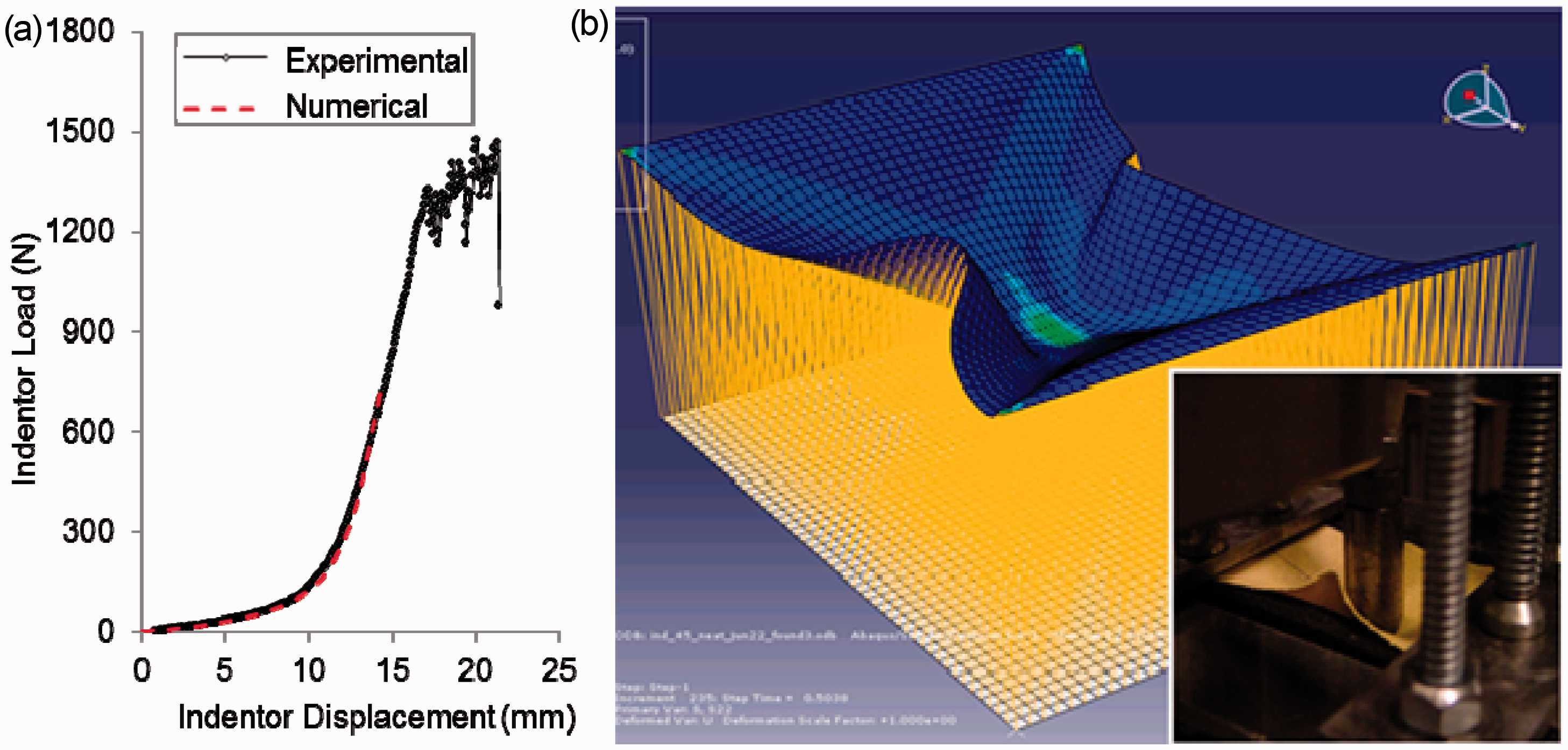
Conclusion
Quasi-static indentation tests performed on uniaxial and 45° off-axial Kevlar K706 coupons with and without an elastic foundation were used to investigate failure modes and mechanisms. Two failure modes were identified – yarn breakage and yarn sliding, depending on the configurations of the tests. A stress-based failure criterion in conjunction with a homogenized continuum constitutive model was implemented in numerical simulations to predict load–displacement behavior and failure load for the uniaxial case with good accuracy. For the 45° off-axial case, an estimation of onset of failure based on yarn locking is achieved. Failure in the 45° off-axial case was due to yarn sliding at the corners. The yarn rotations at the failure location obtained from the simulations serve as an indicator of the onset of failure in the 45° off-axis case. Modeling the yarn sliding failure mode for off-axis indentation completely and accurately requires the incorporation of interaction between yarns at the cross-over points in the constitutive model. The deformed shape and load–displacement behavior for the combined indentation with the elastic foundation are accurately captured by the model. This approach provides a relatively simple, computationally efficient means to predict failure due to yarn-scale phenomenon using homogenized properties for the fabric.
Footnotes
Funding
This work was supported by the Army Research Office (grant no. W911NF-05-2-0006).