
Abstract
Composite-forming processes involve mechanical interactions at the ply, tow, and filament level. The deformations that occur during forming processes are governed by friction between the contacting tows on the mesoscopic level and consequently between filaments on the microscopic level. A thorough understanding of the frictional properties at the level of individual filaments is essential to understand and to predict the macroscopic deformations of a textile reinforcement during forming. This work presents a contact mechanics modeling approach to provide a theoretical background of the frictional behavior of dry fibrous tows in contact with each other. The predicted frictional behavior is in qualitative and quantitative agreement with experimentally observed frictional forces of carbon fiber tows in sliding contact. The relative orientation of the contacting tows is of great importance for the developed frictional forces in the contact.
High performance fibrous tows mainly find their application in structural composites, which consist of a thermoplastic or thermoset matrix and continuous fibrous tows for reinforcement. These continuous fibrous tows deform during the forming phase of production processes, for example when draping dry fabric prior to resin transfer molding (RTM). The tows conform to the local shape of the tool surface on which the composite part is being manufactured. Usually, several plies are used in a composite part, which also leads to inter-tow contacts. Local cross-sectional changes occur in the tow due to the induced loads, which are mainly transferred in the form of friction. The tow orientation and the filament distribution affect the mechanical properties of the composite part to a large extent. Knowledge of the tow orientation and tow deformation behavior is therefore essential to control the desired product quality in terms of mechanical performance, dimensional accuracy, and visual appearance.
The frictional behavior of fibrous tows during processing typically involves intra-tow (on the microscopic filament scale), inter-tow, and tow–metal interactions. This work deals with the frictional behavior of the inter-tow system, i.e. the frictional behavior of tow–tow contacts. A study on the frictional behavior of tow–metal contact is described in another paper. 1
Several researchers have investigated the frictional behavior of contacting fibrous tows.2–8 These experiments were performed on different setup types for a variety of experimental parameters. In 2009, Yuksekkaya provided an overview describing the majority of these experiments. 9
Experimental work on the frictional behavior of fibrous tows showed that inter-filament friction and surface interactions determine the deformation behavior of the fibrous tows.
10
Capstan experiments consisted of measuring forces in the ends of fibrous tow specimens wrapped around a rotating friction drum covered with fibrous tow material. This setup is schematically illustrated in Figure 1. The current work proposes a contact mechanics modeling approach of tow friction to provide a theoretical understanding of the observed behavior.
Schematic description of the capstan experiment for friction characterization of fibrous tows. A tow specimen is wrapped around a friction drum on which tows of the same material are attached in either a parallel (left) or perpendicular (right) orientation.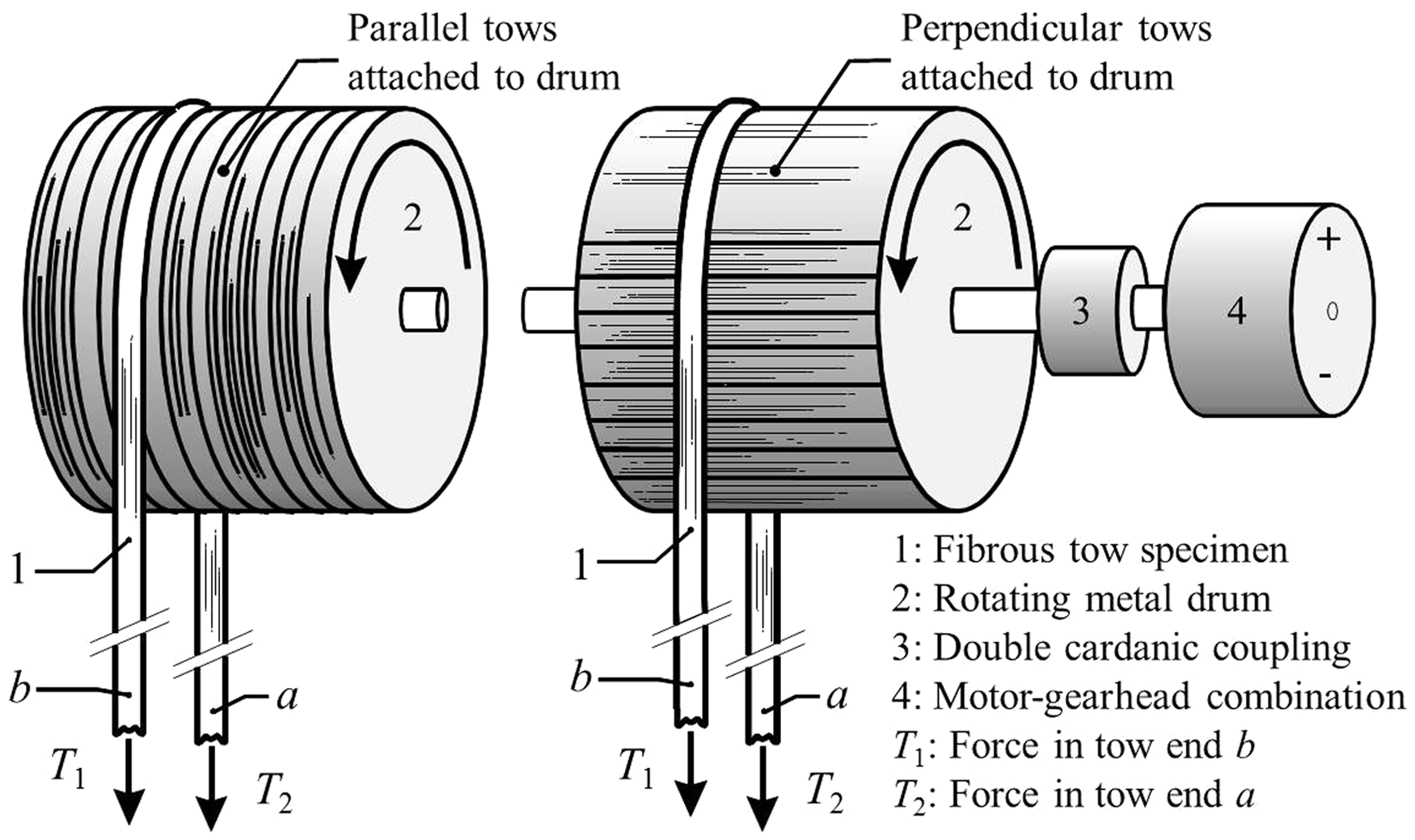
A model for the contact mechanics of fibrous tows during forming is proposed in the next section. The scope of the model and material properties are explained, followed by a derivation of typical loading conditions for tow material, based on a capstan friction experiment. Subsequently, a contact mechanics approach is proposed to determine the contact area for both perpendicular and parallel sliding tow contact. The effect of adhesion on the developed frictional force between perpendicular tows in sliding contact is also assessed. The model results are presented in the results section, followed by a comparison with experimental data in the discussion section to validate the model.
Contact mechanics modeling approach
This section deals with the model assumptions and presents the contact mechanics approach of the contact area between tows in sliding contact.
Scope of the modeling approach
The contact mechanics approach of tow deformation behavior is based on the relation between the exerted compressive load on sliding filaments in fibrous tows and the developed frictional force. The area of contact between the filament and the fibrous counterface is load dependent.11–13 Consequently, this results in a load dependency of the frictional force between the tow and the counterface. Howell and Mazur proposed the following empirical friction law:
11

Roselman and Tabor described the frictional behavior of single carbon filaments in contact in the 1970s.15,16 The friction equation consists of a shear friction part involving the product of a real contact area Ar between the contacting filaments with an interfacial shear strength τ, and a ploughing part P:
Material
Manufacturer data (M) of the Torayca T300JB carbon tow material used in the contact model. Additional data of equivalent carbon tow material from literature sources is indicated with the corresponding reference

Figure 2 shows a scanning electron microscopy (SEM) micrograph of a typical carbon filament. The surface topography of the carbon filament consists of ridges in the axial filament direction. The typically observed radius of curvature Rridge of approximately 100 nm is comparable to the value of Rridge ≈ 200 nm reported by Roselman and Tabor.
15
These dimensions apply to the specific type of carbon fibers used in this research. Note that the ridge dimensions of other types of carbon filaments, such as pitch-based variants or filaments from a different manufacturer, can deviate from the dimensions reported here. The specific geometry in this work is used as a ball-park figure and it is not intended to represent a wide variety of carbon filaments.
Micrograph (SEM) of a carbon filament with a typical diameter of 7.0 µm. The ridges in the axial filament direction are clearly visible; the radius of curvature Rridge is approximately 100 nm.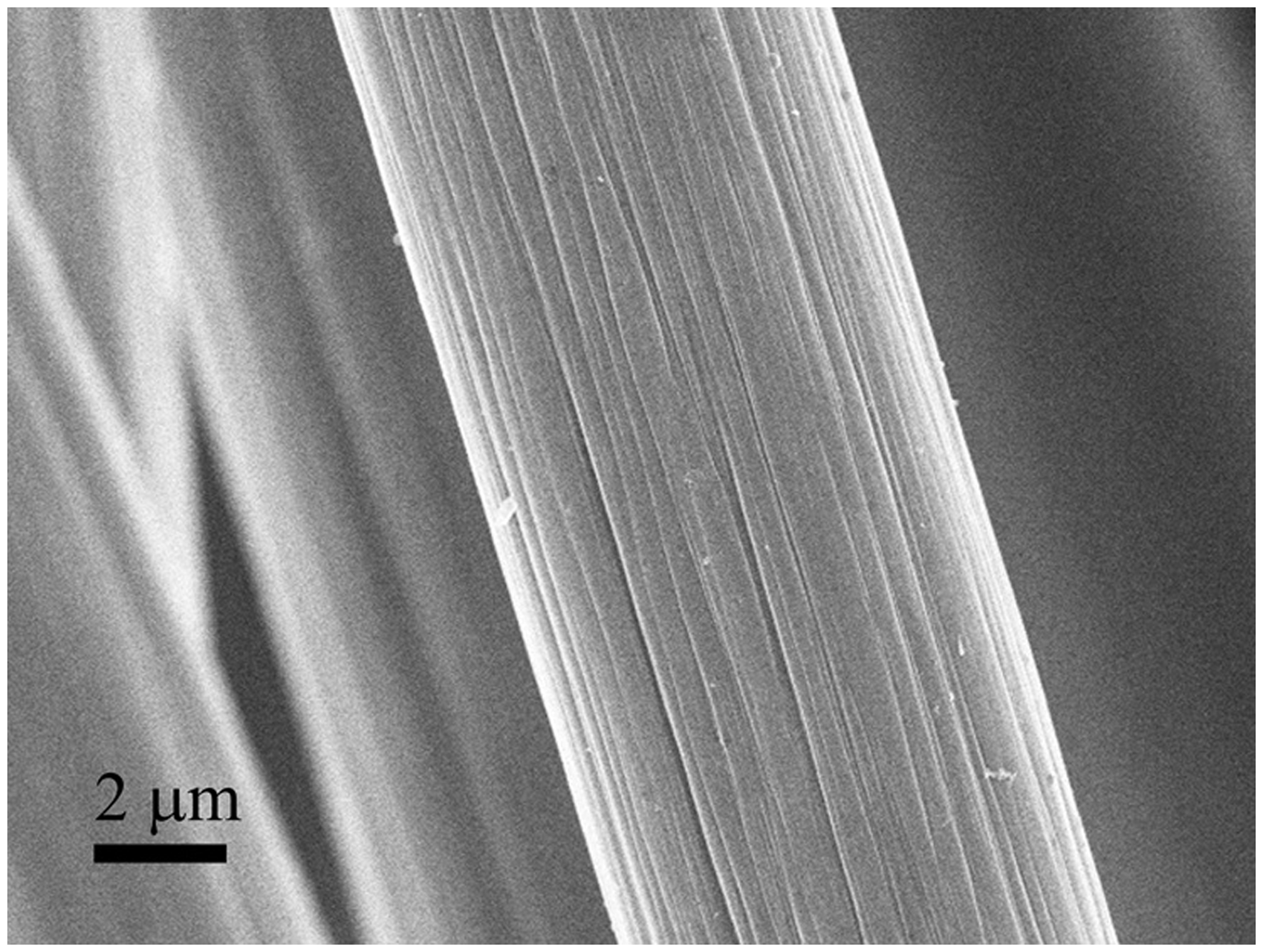
From tow to filament load
The typical compressive load acting on a single filament is derived from actual measurement data, obtained in the aforementioned capstan friction experiment.
10
Figure 1 illustrates the experiment schematically. A fibrous tow was draped on a metal friction drum, having a radius Rdrum = 25.0 mm, with a known wrapping angle θwrap. The tensile tow end loads T1 at θ1 = 0 and T2 at θ2 = π [rad] were measured. An apparent coefficient of friction μapp can be obtained from the capstan relation:


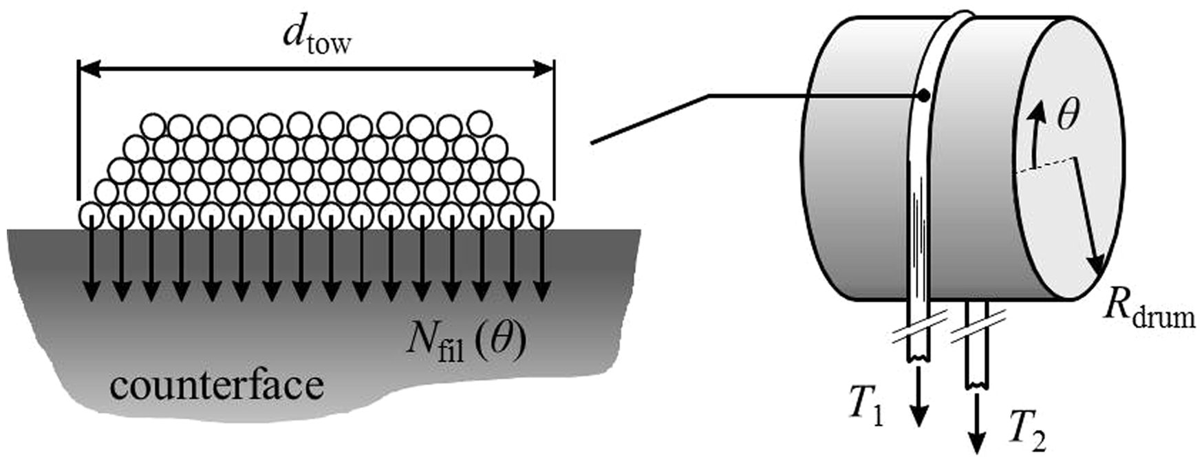
The distributed normal load Ntow (in N/m arc length) in the contact between the stationary and moving tows follows directly from load equilibrium of an infinitesimal part of the stationary tow, Appendix 1 contains the derivation:
Uniform normal load distribution assumption of the bottom filaments of the stationary fibrous tow. The contacting counterface tows are oriented perpendicularly or parallel to the stationary tow. Note that the friction drum rotates in the opposite direction of θ (as illustrated in Figure 1).

Perpendicular tow contact
The contact between filaments with radius Rfil under a perpendicular orientation is modeled with two crossed cylinders, as illustrated in Figure 4. The radius of curvature of the capstan friction drum Rdrum = 25.0 mm is large compared to the filament radius Rfil = 3.5 µm and is therefore approximated by a flat surface. Using a contact mechanics analogy, the crossed cylinders can be represented by a sphere indenting a plane. The principal reduced radius of curvature Rm of the equivalent contact is defined as:
Schematic illustration of filaments in perpendicular contact. The contact between the filaments is represented by the analogy of a sphere indenting an elastic half-plane. The contact area Ap is circular with contact radius ap.
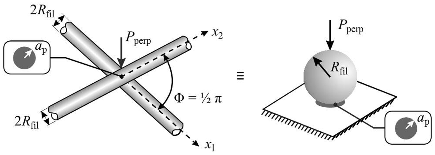
The compressive load Pperp on the sphere in the contact analogy is a load in newtons. This force is derived from the local normal filament load in equation (7). Multiplication of Nfil(θ) with a projected arc length corresponding to one crossing filament diameter leads to the load (in newtons) of the perpendicular contact at the angular coordinate θ:


The relevant material properties are listed in Table 1. The obtained circular contact area Ap = π ap2 is a first approximation due to the smooth filament surface assumption. This first approximation does not account for the presence of the ridges on the filament surface, illustrated in Figure 2. The typical radius of curvature of the ridge of approximately 100 nm is small compared to the filament radius. Based on the dimension of the first approximation contact radius ap, the perpendicular contact between carbon filaments can take place at one or two ridges. Calculating the contact area between these ridges should therefore provide a more realistic representation of the perpendicular tow friction experiment. For that purpose, the carbon filament-filament contact areas as a function of load are also modeled for the radius of a ridge Rridge. Figure 5 illustrates the contact analogies for two situations, i.e. the contact between one ridge on each filament, denoted 1 × 1, and the contact between two ridges on each filament, denoted 2 × 2. The 1 × 1 contact analogy is equivalent to the aforementioned case of the contact of smooth filaments. The 2 × 2 contact of ridges was modeled by evenly distributing the load Pperp over four individual contact areas. The resulting contact radii are ap,1×1 and ap,2×2. Additionally, 1 × 1 ridge contact calculations for Rridge = 200 nm were performed to assess the sensitivity of the predicted contact area to the radius of a ridge. The results of the contact calculations as a function of the distributed normal filament load are interpreted in the discussion section.
Analogies for the determination of the contact radii ap,1×1 and ap,2×2 of perpendicularly crossed filaments. The contact occurs between one or two ridges of each filament.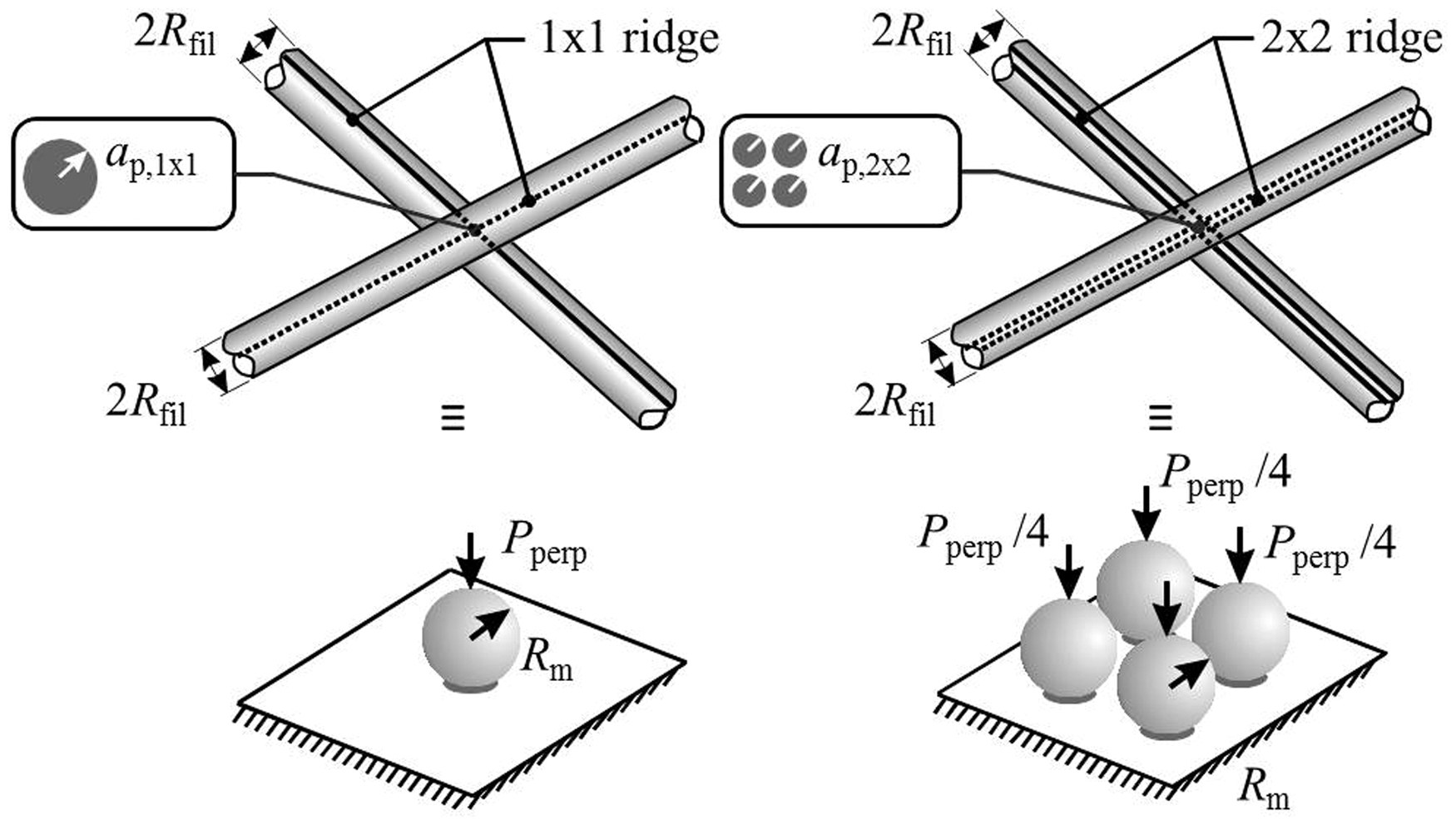
Furthermore, a Maugis–Dugdale (MD) contact analysis provides insight into the contribution to the contact area of adhesion between the filaments.22–24 The carbon fiber material in this work is relatively soft compared to metals. Johnson and Greenwood showed that attractive forces due to adhesion between contacting materials can have a significant effect on the real contact area and thus the theoretical frictional force between contacting filaments. 23 Different models exist to account for this adhesion effect.22–24 The contact of most (technical) fibrous materials is well represented by the Maugis–Dugdale model, which is based on several filament properties: the work of adhesion, the transverse stiffness, and the geometry.22,23 The attractive forces between the filaments result in a non-zero contact area without an externally applied load. Therefore, the contact radius aMD obtained from the Maugis–Dugdale analysis is larger than the Hertzian equivalent, which does not account for the effect of adhesion between the contacting filaments. The procedure to obtain the load–area relation for adhesive contact according to Maugis–Dugdale is presented in Appendix 2.
Summarizing, the contact between perpendicularly oriented filaments is investigated for three different surface geometries represented by Rfil = 3.5 µm for a smooth filament surface assumption, and Rridge = 100 nm as well as Rridge = 200 nm when accounting for surface irregularities on the carbon filaments as illustrated in Figure 2. A variation of the amount of contacting ridges was taken into account; this is illustrated schematically in Figure 5. The contact calculations were performed with (MD) and without (Hertz) accounting for the contribution of adhesion between the contacting filaments. The results are presented in the next section.
Parallel and nearly parallel tow contact
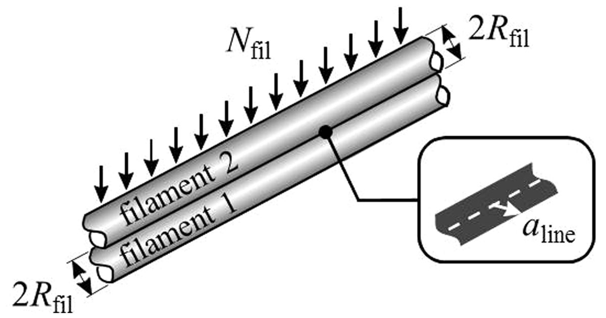
A perfectly parallel orientation between the filaments of the stationary and sliding tows would result in a rectangular contact area in the axial direction of the filaments, as illustrated in Figure 6. For a Hertzian line contact, the half-width of contact aline is:
21
Perfectly parallel filament contact with the distributed normal filament load Nfil. The contact area is rectangular with the half-width of contact aline. Filament 1 is attached to the rotating drum; filament 2 is part of the wrapped tow, which is stationary.
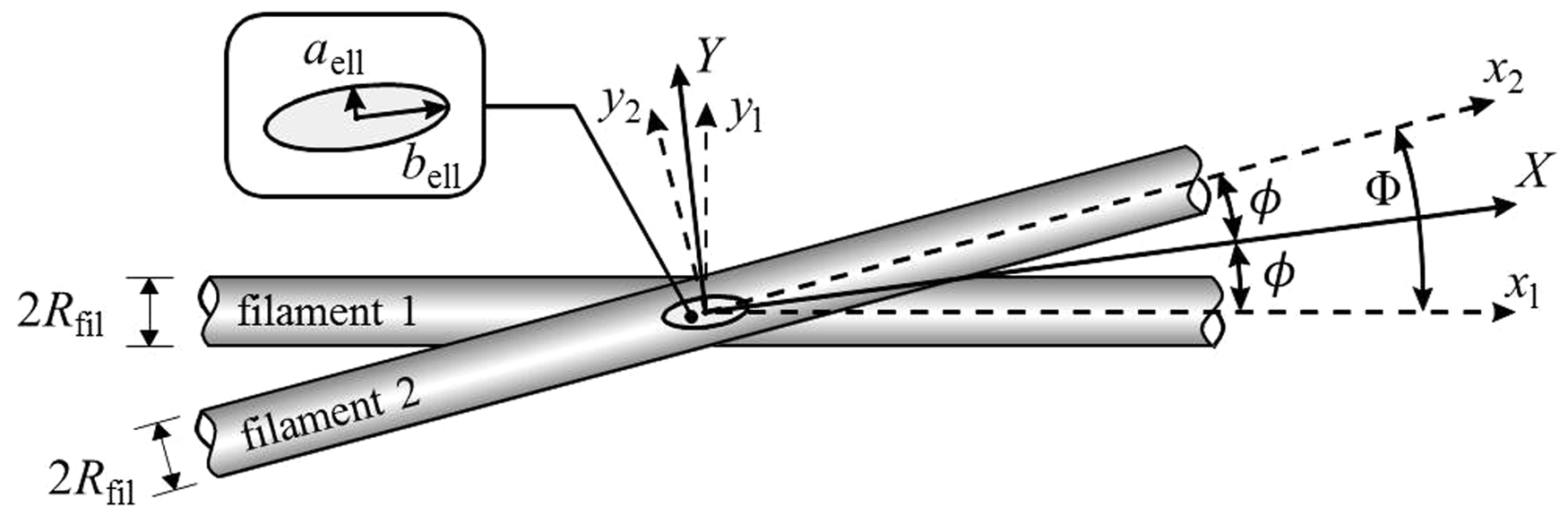
However, the filaments in the experimental setup contacted each other under a small angle, as illustrated in Figure 7. The estimated relative orientation of the filaments Φ was obtained from experimental observations. The filaments in the stationary wrapped tow crossed a number noblique of moving filaments as a result of the relative orientation. This relative orientation originates from the fact that the stationary tow was wound on the friction drum. The winding pitch of the tow on the drum is equal to the tow width dtow. Thus, a filament from the stationary tow, which is wrapped with θwrap = π around the moving tow/friction drum arrangement, crosses the number of filaments noblique in half of the tow width dtow. Consequently, the number of filaments in contact follows from half the tow width divided by the filament diameter 2Rfil:
Oblique filament contact with the relative filament orientation Φ = 2ϕ representing the nearly parallel orientation of filaments. The contact area is elliptic with semi-minor axis aell and semi-major axis bell. Filament 1 is attached to the rotating drum; filament 2 is part of the wrapped tow, which is stationary.

Tow geometry input data for the oblique tow–tow contact model, representing nearly parallel contact of the filaments

The compressive load in newtons in each filament-to-filament contact then follows from the distributed filament load Nfil, derived in equation (7), multiplied by the distance between two oblique filament crossings:

The contact analogy for the oblique contact of geometrically identical cylinders is that of an ellipsoidal punch with the principal relative radii of curvature RX and RY which contain the translated curvatures of the contacting bodies. These radii are defined as follows:21,27


The semi-minor axis aell, the semi-major axis bell of the elliptic contact area and the approach distance of the deformed filament surfaces in the center of the contact δ follow from the derived contact geometry and the applied normal load Npar, resulting in:
26


Summarizing, the contact between perfectly parallel (Φ = 0°) and nearly parallel or obliquely (Φ = 2°) oriented filaments is investigated for three different surface geometry assumptions represented by Rfil = 3.5 µm for a smooth filament surface assumption, and Rridge = 100 nm as well as Rridge = 200 nm when accounting for surface irregularities on the carbon filaments, as illustrated in Figure 2. A variation of the amount of contacting ridges was taken into account. The contact calculations were performed without taking the contribution of adhesion between the contacting filaments into account, i.e. using a Hertzian contact approach. The results are presented in the next section.
Results
The contact model results are presented separately for the perpendicular and parallel relative tow orientations. Contact area predictions with and without accounting for surface irregularities of the filaments are presented.
Perpendicular orientation
Figure 8 shows the contact area per meter contacting filament for both the smooth filament surface assumption (Rfil) and the contacting ridge situations with varying Rridge. The graph clearly shows the influence of the assumed contact type on the predicted real area of contact, i.e. a smooth filament (Rfil) versus a filament surface with ridges (Rridge).
Contact area Ar as a function of the distributed normal filament load Nfil for perpendicular contact of two filaments. The contact areas are shown for three different contact geometries: Rfil = 3.5 µm represents a smooth filament-filament contact, the contact of 1x1 small ridges is represented by Rridge = 100 nm, the contact of 1 × 1 large ridges by Rridge = 200 nm. The contact areas are shown with adhesion contribution (MD, w = 95.1 mJ/m2) and without adhesion contribution (Hertz).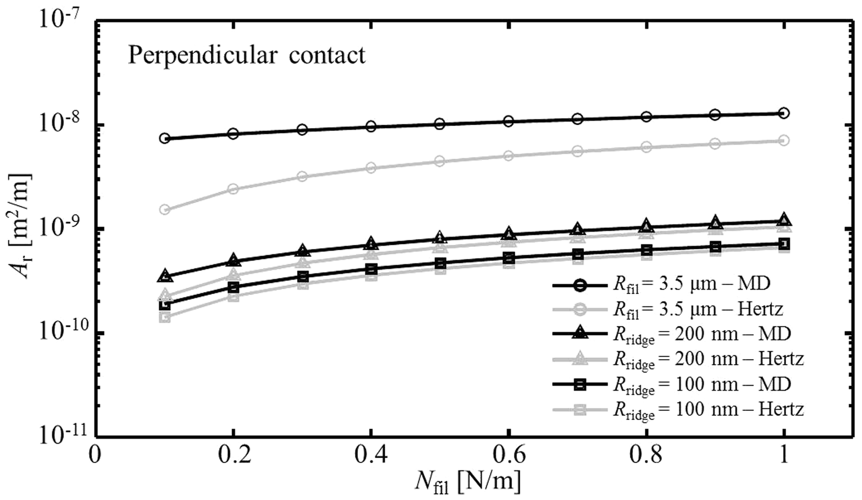
The maximum applied normal distributed load in the experiment is estimated to be 0.5 N/m. The radius of the circular contact area ap for a smooth filament-filament contact is 99 nm at this load, the maximum pressure in the contact is 169 MPa. For the 1 × 1 small ridge contact, the radius ap is 30 nm, with a maximum pressure in the contact of 1.8 GPa. A remark on the high maximum pressure for the 1 × 1 small ridge contact is made in the discussion section.
The adhesion contribution to the contact area is visible in Figure 8 by comparing the black curves with the grey curves with the same markers. The contribution of adhesion to the contact is larger for the smooth filament situation, i.e. the curves with the circular markers, than for the ridge-to-ridge contacts, i.e. the curves with the triangular and square markers. The dimensionless normalized load range is defined as the ratio of the absolute applied load Pperp and the adhesive pull-off force 2πwRm required to separate the contacting bodies:
23

Parallel orientation
The real contact area as a function of the distributed filament load for tows in a nearly parallel orientation is visualized in Figure 9. The results are shown for Hertzian contact, i.e. adhesion effects were not taken into account. The black dotted curves represent the real contact area per unit filament length for a perfectly parallel orientation of the filaments, using equation (13). However, the aforementioned small relative angle of orientation Φ = 2° between the contacting filaments is expected to provide a more realistic representation of the experiment. The gray curves in Figure 9 were obtained by calculating the elliptic contacts along the wrapped length of a filament using the general Hertzian elliptic contact theory, explained in the previous section.
Contact area Ar as a function of the distributed filament load for perfectly parallel (Φ = 0°) and nearly parallel (Φ = 2°) contact of two filaments. The contact areas are shown for three different geometries: Rfil = 3.5 µm represents the smooth filament assumption, the contact of 1 × 1 small ridges is represented by Rridge = 100 nm, the contact of 1 × 1 large ridges by Rridge = 200 nm. The areas are shown for Hertzian contact, i.e. without adhesion contribution.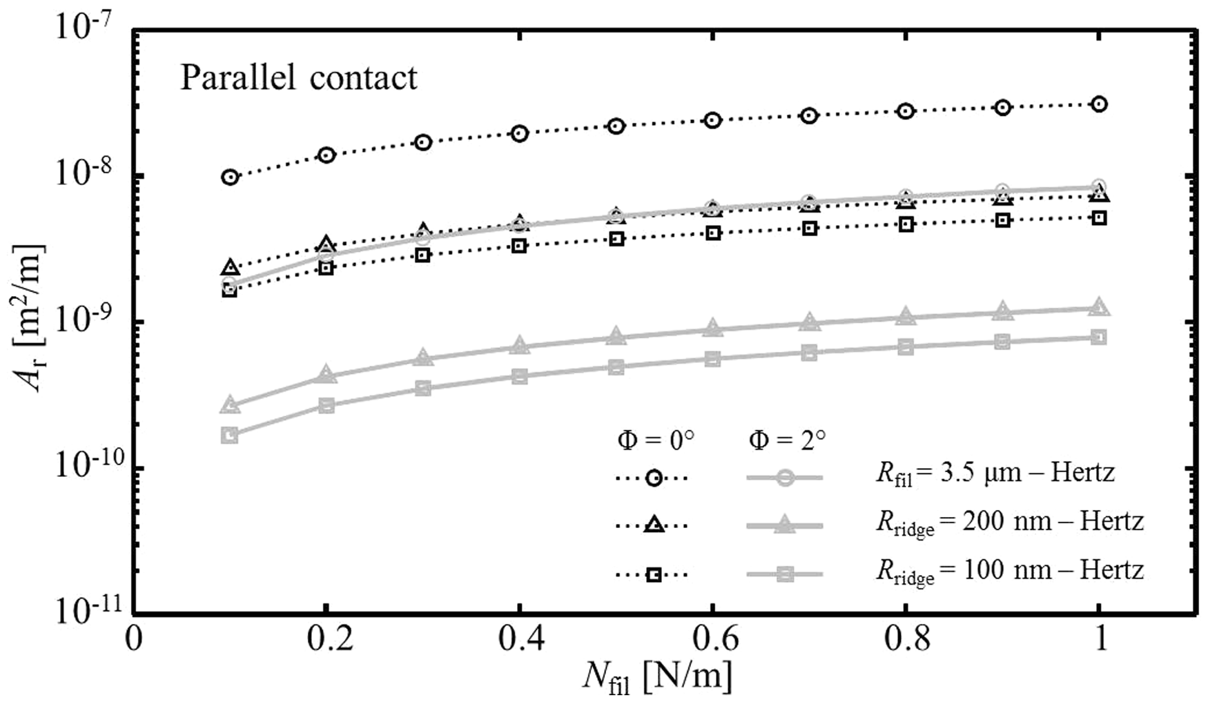
The smooth filament assumption leads to a contact area of about a factor ten higher than the predictions for ridge-to-ridge contact. Furthermore, Figure 9 shows that the real area of contact per unit filament length for the perfectly parallel contact (Φ = 0°) is about an order of magnitude higher than the predicted contact for a small angle Φ = 2° between the stationary and moving filaments. The model results for both the perpendicular and parallel tow orientations are discussed in more detail in the discussion section.
Discussion
The expected frictional force between the contacting filaments can be predicted from equation (2). The obtained frictional force is compared with the experimental results to assess the model performance. Furthermore, several aspects of the model are discussed.
Comparison with experimental results
The model predictions are related to the experimental observations by comparing the measured frictional force Ff = T2 – T1 with a frictional force prediction based on equation (2).
The normal loads on the filaments were used to predict the frictional force for a small arc length segment Δs = Δθ Rdrum of the contacting filaments:
Predicted frictional force Ff as a function of the wrapping angle θwrap on the capstan setup for various ridge-to-ridge contact situations in a perpendicular orientation. The star symbol indicates the measured force in the experiment; the dotted line shows the frictional force based on equation (5) with μapp = 0.13. The Hertz curves represent the friction without adhesion contribution, whereas the MD curves account for the effect of adhesion. The frictional force curve for 2 × 2 ridge contact of Rridge = 100 nm coincides with that of 1 × 1 ridge contact with Rridge = 200 nm for Hertzian contact.

The frictional force prediction for the smooth filament assumption overestimates the measured friction by more than an order of magnitude and was therefore not included in the graph. The predicted frictional forces are in the same range as the experimental observations for perpendicular contact between the ridges on the carbon filaments. The contribution of adhesion to the friction is limited, due to the small radius of curvature of the contacting ridges. As indicated in the legend of the graph in Figure 10, the solid grey Ff -curve representing the Hertzian 1 × 1 ridge contact with Rridge = 200 nm coincides with that of the 2 × 2 small ridge contact with Rridge = 100 nm.
However, for the MD-curve, i.e. taking the contribution of adhesion into account, the friction is slightly higher for the 2 × 2 small ridge contact than for the 1 × 1 large ridge contact. Thus, the effect of adhesion for one large contact is smaller than the effect for several small contacts, which have the same total Hertzian contact area. It is very likely that a mixture of 1 × 1, 2 × 2, and 1 × 2 contacts occurs in an actual contact situation. Although the distribution of each of the three combinations is not known, the frictional force as a result of the mixture of the aforementioned contact situations can be expected to lie close to the experimentally observed value indicated by the star symbol in Figure 10.
Figure 11 shows the results for the parallel tow contact, i.e. under a small angle Φ = 2°. The Hertzian contact is shown for the same interfacial shear strength as for perpendicular contact, i.e. τ = 100 MPa. The predicted frictional force appears to be in qualitative as well as quantitative agreement with the experimentally observed value indicated by the star symbol. Thus, the modeled oblique contact at a relative angle Φ = 2° of ridges on the filaments appears to provide a good representation of the actual experiment.
Predicted frictional force Ff as a function of the wrapping angle θwrap on the capstan setup for various ridge-to-ridge contact situations in nearly parallel contact, i.e. Φ = 2°. The star symbol indicates the measured force in the experiment; the dotted line shows the calculated frictional force based on equation (5) with μapp = 0.23. The frictional force curve for 2 × 2 ridge contact of Rridge = 100 nm coincides with that of 1 × 1 ridge contact with Rridge = 200 nm. The solid black line represents the contact for a perfectly parallel orientation of filaments, i.e. Φ = 0°.
The contact area ellipticity, which is the ratio of the major and the minor semi-axis of the contact ellipse, is rather high with values up to 135 for a distributed load of 1 N/m. It is likely that a deviation occurs between the shape of the modeled Hertzian and the actual filament–filament contact. Additionally, one should note that the major semi-axis dimension bell = 8.8 µm of the contact ellipse is of the same order of magnitude as the filament diameter for normal distributed loads around 1 N/m (for smooth filament contact; the corresponding minor semi-axis dimension aell = 67 nm). For the 1 × 1 ridge contact, these values are aell = 20 nm and bell = 2.7 µm. This implies that the small deformation assumption of the Hertzian contact model does not apply. A maximum contact pressure of 1.9 GPa (178 MPa) occurs for the 1 × 1 small ridge (smooth filament) contact with a distributed normal load of 1 N/m. In the case of the capstan experiment a maximum contact pressure of 1.5 GPa (142 MPa) can be expected for the maximum applied distributed normal load of 0.5 N/m. This seems to be a rather high pressure to still fall within the assumed elastic material deformation regime, although the exact compressive strength of carbon filaments is not known accurately to date. Altogether, it seems plausible that contact between multiple ridges occurs in the actual filament-filament contact.
The thin solid black curve in Figure 11 depicts the frictional force prediction for 1 × 1 ridge-to-ridge (Rridge = 100 nm) contact in perfectly parallel orientation, i.e. Φ = 0°. This clearly illustrates the overestimation of the frictional force Ff when a perfectly parallel orientation of the filaments is assumed. A mixture of ridge-to-ridge contact situations is expected to apply in reality, similar to the case of perpendicular contact.
Model assumptions
Several simplifying assumptions were made in the contact modeling procedure. First, a uniform distribution of the normal loads Nfil on each filament in the bottom layer of the stationary tow was assumed, as illustrated in Figure 3. This approximation neglects load variations at, for example, the edges of the tow, where fewer filaments are present to transmit the normal load to the bottom layer. The true value of Nfil is expected to vary slightly along the width of the tow. However, the current approach appears to give an adequate representation.
Second, an ideal packing of filaments in the tow was assumed, which is not the case in reality. A small amount of entangled or misaligned filaments was present in the tow material, disturbing the parallel arrangement of filaments within a tow, although the supplied tow material had no intentionally applied twist. However, these effects are very likely averaged out in the capstan experiment. Furthermore, the close packing assumption implies that there is no spacing between the filaments in the tow, thus the amount of contacting filaments in the bottom layer of the stationary tow nfil is an upper bound estimate of the actual situation. Variations of nfil along the wrapped length lwrap of the tow are expected to occur as well, due to a varying width of the tow on the capstan drum. The effect of the tow width variation was not taken into account in the current work. Another effect that was not taken into account is the contribution of digging in of filaments of the contacting tows. This effect, where a filament is in contact with two other filaments under a wedge- like angle, is described in detail in previous work. 10 It leads to an observed apparent coefficient of friction μapp of the tow on a capstan setup that is about 15% higher than the actual coefficient of friction at the filament level. However, due to the observed relative orientation of the tows, digging in is only expected to occur locally during friction experiments, i.e. at contact lengths smaller than the filament contact length on the capstan lwrap. The values of μapp on the tow and filament level were therefore assumed equal in this study. However, additional experimental work should be performed to rule out or confirm the presence of significant digging in of filaments.
Third, the large contact lengths between ridges on the filaments for the parallel and oblique contact cases might suggest that the surface roughness varies significantly within the contact length. In fact, mainly the large wavelengths of the surface roughness would influence the roughness significantly. However, the relatively low bending rigidity of the filaments will compensate for this wavelength, leaving the measured roughness and thus the ridged structure dominant in the analysis. The discontinuous nature of the ridges is most likely averaged out due to the large number of contacts.
Future work should focus on the assumptions regarding the amount of filaments in oblique contact noblique and the corresponding contact load Ppar. Furthermore, the effects of small amounts of twist in the tow were not taken into account. The filaments of twisted tows in contact have a different relative contact angle Φ than those in the currently assumed parallel arrangement of filaments within the tows. The modeling approach in this work was presented for carbon tow material; however, the frictional behavior of any fibrous material can be modeled using this approach as long as the surface characteristics of the filaments are taken into account in the modeling approach.
Conclusions
A contact mechanics model for the prediction of the friction between sliding tows has been developed. The model accounts for the difference in frictional behavior between perpendicular and nearly parallel relative tow orientations. An agreement on the order of magnitude level was found between the contact model and observations from capstan experiments. The results of this research are limited to this order of magnitude level due to the uncertain value of the interfacial shear strength τ and the simplifications in the assumptions behind the proposed modeling approach.
Because the approximation of a smooth filament surface led to an overestimation of the frictional force between sliding tows, the surface characteristics of carbon filaments were taken into account. This resulted in a good agreement between the contact model and the experimental results in the case of perpendicular and nearly parallel contact between tows. The contact area and hence the frictional force in the tow were overestimated for perfectly parallel contact of the filaments in the tow. Further investigation of the contact and load assumptions are required for an improved prediction of the frictional behavior of sliding fibrous tows with, for example, intentionally applied twist. The current modeling approach should support the prediction of all relative tow orientations. Additional experiments at intermediate relative tow orientations can further improve the physical understanding of tow-tow friction and confirm the validity of the proposed modeling approach.
The contact model in this work provides an approximate (order of magnitude) physical explanation for the experimentally observed orientation dependence of tow friction. The mesoscopic frictional behavior of fibrous tows was explained by taking microscopic characteristics of the constituents into account.
The orientation-dependent frictional behavior of fibrous tows was assessed on a mesoscopic level. The frictional behavior of textile reinforcements like woven fabrics is typically assessed on the macroscopic ply level. The insights on the level of fibrous tows can thus provide a coupling between the macroscopic deformation of a textile reinforcement and the resulting deformations on the microscopic filament level.
Footnotes
Funding
This study was supported by the Stichting Technologie en Wetenschap (STW) van der Leeuw (grant number STW-06182).
Acknowledgments
The authors wish to thank Ten Cate Advanced Composites and vom Baur for their support and supply of testing materials.