
Abstract
This research work describes a new technique for producing staple fiber core-filament wrapped composite yarn, with the help of an innovative multifilament spreading method, using a slightly modified ring frame. The purpose is to develop an efficient and economic process for spreading the multifilament uniformly, to realize and improve the wrapping of the multifilament around staple core. Scanning electron microscopy was used to study the role of micro grooves’ dimensions in the formation of the multifilament layer and related effects on cover spun yarn properties. A modified ring frame was used to make 48 tex (12 Ne) composite yarn, which was compared to a similar composite yarn made on a conventional ring frame, for the tensile and hairiness properties. It was concluded that this mechanical spreading method can be used to increase the spinnability for short staple fibers and to overcome the problems associated with other spreading techniques and also can help to improve the breaking extension and hairiness properties of the composite yarn without the decrease of yarn tenacity.
Composite yarn spinning techniques using multifilament and staple fiber components have been under focus for further advancement during the last three decades. 1 Filaments and staple fibers can be combined to form various composite yarn structures using a conventional ring frame with a few modifications.2–7 Progress has been made in bi-component composite yarn spinning using various multifilament spreading techniques including pneumatic, acoustic and electrostatic spreading.4,8–10 The multifilament spreading width is of special importance and is the main influencing factor for the composite yarn structure and properties.11–16
Separation of mono filaments, which can be done using spreading apparatus, is considered to be an effective way to overcome composite yarn imperfections.4,6,9,10,17,18 It is because multifilament spreading width affects the resultant yarn structure and properties to a greater extent.8,12,16,19
The most common method stated in previous research works for spreading multifilament yarn into a mono filament sheet involves the use of an electrostatic field, 20 which requires high voltage and continuous water supply to pass on electrical conductance to the filaments. Hence, this method has safety problems.8,20,21
Some researchers have also worked out various methods to form a multifilament layer or ribbon through mechanical spreading means to form a staple core-filament wrapped composite yarn structure. Multifilament web can be formed by spreading of the multifilament strand, having little or no twist and placing yarn under adequate tension so that multifilaments are free to separate. The presence of inherent twist between the multifilaments might affect the evenness and uniformity of spreading.22,23 A multifilament wrap-staple core yarn structure can be an efficient approach to form composite yarn with better surface and mechanical properties. Multifilament wrapping can also help to utilize coarser fibers as core, which cannot either be spun into a finer yarn or will result in a poor quality yarn otherwise.24,25
This research work is based on an innovative method of multifilament spreading with the help of a micro-grooved aluminum roller.26,27 A grooved roller can help in spreading the multifilament yarn into a uniform layer of multifilament, which can hold and wrap the staple fiber component to form a staple fiber core/filament wrapped composite yarn. We also briefly examined the effects of this spreading technique on the composite yarn properties.
Experimental details
Preparation of spreading roller
The aluminum spreading roller used for this research work was 25 mm long having a 12 mm diameter. The mechanical engraving method was used to form fine grooves on the roller’s surface. The micro grooves’ dimensions, such as width and depth, are of significant importance to the roller spreading function. Based on some preliminary experiments, 10–12 and 12–15 µm were chosen as the groove width and depth, respectively. On the spreading roller surface, the micro grooves form an approximately 30° angle with the center line (C), as shown in Figure 1.
Micro-grooved spreading roller.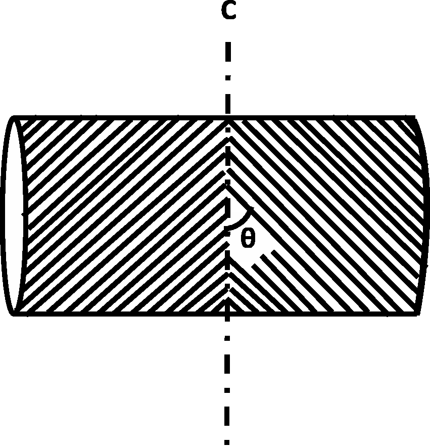
A positively driven grooved roller when rotated at relatively higher speed and along the path of fed multifilament yarn can separate the multifilament to form a layer. Figure 2 illustrates the process of multifilament spreading.
Spreading of multifilament yarn due to the grooved roller surface.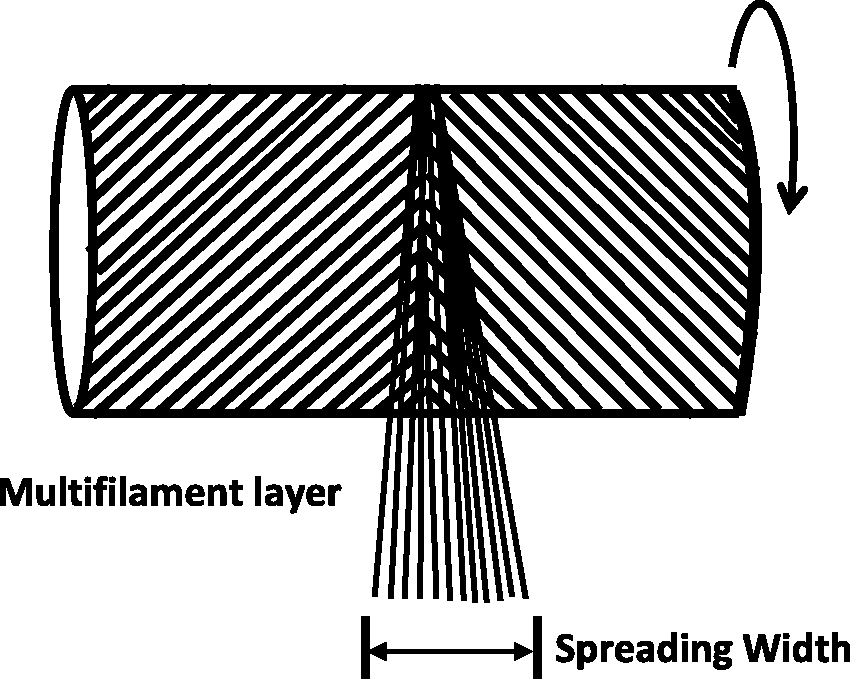
Mounting spreading roller assembly
The micro-grooved roller (R) and a multifilament guide (G) were mounted on a conventional ring frame for staple core-filament wrapped composite yarn spinning. The grooved roller is positioned in the gap between middle roller aprons and front roller, which can rotate at different speeds with the help of an attached motor.
27
The height and distance between the spreading roller and front roller can be adjusted with the help of connecting screws. Polyester multifilament yarn was passed through the tension discs (T), filament guider (H) and pre-spreading guide (G) and fed to the grooved roller precisely into the spreading center (C). Micro grooves on the aluminum roller surface spread the polyester multifilament yarn into a multifilament layer, before feeding to the front roller. The spread multifilament layer and drafted cotton roving are fed into the nip of front rollers, whereas the cotton roving is placed right below and in the center of the multifilament layer. This process is illustrated in Figure 3.
Ring frame modification diagram.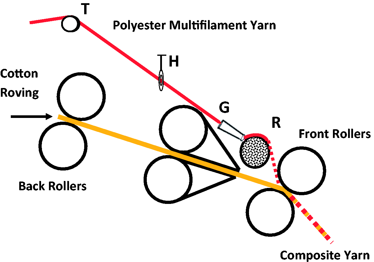
Shape and position of multifilament guide
The shape and position of the multifilament guide (G) also plays an important role. The filament guide should be placed very close and opposite to the spreading center (C) of the grooved roller to help uniform spreading. The multifilament guide used for this work had a special shape and the dimensions as shown in Figure 4(a). The size of the multifilament guide’s front hole, which is closer to the spreading roller, should be very small (i.e. 3.0–5.0 mm) to control the feeding position of the multifilament yarn, whereas the curved shape also facilitates prior spreading and separation of the multifilament, as shown in Figure 4(b). The position of the filament yarn guide should be adjustable, to vary the wrap angle and distance to the spreading roller if needed.
(a) Shape and dimensions of the multifilament guide. (b) Multifilament pre-spreading due to the curved guide shape.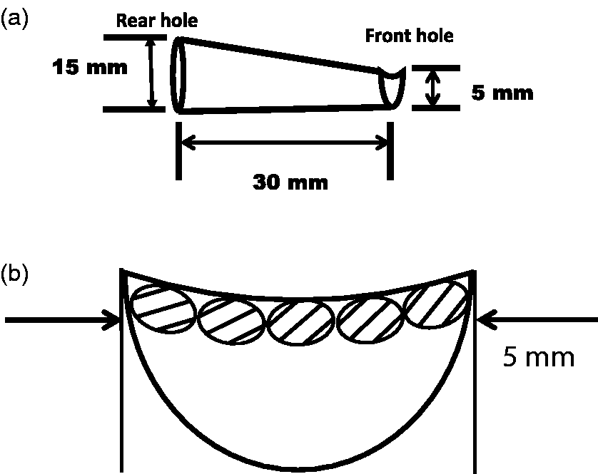
The multifilament guide helps to withstand the excessive frictional force of the dragged multifilament, rubbing against the surface of the spreading roller rotating at higher speeds. Guide should be firmly fixed to avoid any vibrations of filaments that might result in uneven spreading.
Materials and testing
Cotton fiber rovings (size: 467 tex) having a mean fiber length of 24.8 mm, fiber linear density of 155 mtex and micronaire value of 3.40 were used for the staple core and 16.6 tex/36F polyester multifilament was used as the sheath to wrap the fibrous core; in this way 48 tex (twist factor 425) cotton core-polyester wrapped composite yarns were made.
The first composite yarn sample (Y1) was prepared at a conventional ring frame using the common staple core multifilament wrapped spinning technique. Polyester multifilament yarn was passed through guide hooks and fed behind the nip of the front rollers in order to mix with drafted cotton roving, to form the composite yarn. The second composite yarn sample (Y2) was, however, made with the help of the spreading roller assembly mounted on a ring frame. In this case, the polyester multifilament yarn was passed through a special guide and then spread in the form of a multifilament layer before feeding into the nip of the front rollers along with the drafted cotton roving. The average width of the multifilament layer used to prepare Y2 yarn was 6 mm, whereas the spreading roller speed was approximately 750 rpm and the wrap angle of multifilament on the grooved roller was 140°. The composite yarn samples were conditioned for 48 hours under standard conditions 20℃ ± 2℃ and 65% ± 2% relative humidity (RH) prior to testing.
To study the important tensile properties of composite yarns, including breaking strength and extension at break, a total of 20 specimens with a gauge length of 50 cm from each yarn type were tested on a YG061 tensile tester under standard laboratory conditions. For measuring hairiness a YG172 hairiness tester was used at a test speed of 30 m/min and specimen length of 10 m; a total sample length of 100 m for each yarn was tested at standard laboratory conditions.
Results and discussion
Influence of multifilament pre-tension
The multifilament must be kept under adequate tension before coming in contact with the spreading roller, in order to achieve the desired spreading width. Pre-tension on the multifilament bundle helps to control its path and make the spreading function possible because of rubbing against the grooved roller. Pre-tension on the multifilament yarn was 10 cN for these experiments. It is notable that excessive tension hinders the free separation of the multifilament, resulting in clustering or sinking of the multifilament into the core of the composite yarn. The surface of the multifilament is also damaged if pre-tension is too high, and grooves on the roller surface wear off before long. However, if pre-tension is too low, only slight multifilament spreading is possible, which will make the desired filament wrap around the staple core less effective.
Influence of wrap angle on spreading width
Multifilaments are bent against the spreading roller while spreading, making a certain wrap angle to the axis of rotation, as shown in Figure 5. This angle can be changed by adjusting the placement of the multifilament guide (G) and spreading roller (R).
Wrap angle of the multifilament on the spreading roller.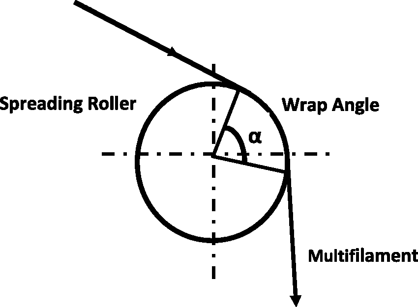
Wrap angles of 90°, 110°, 120° and 140° were used to analyze the effect on multifilament spreading width at various speeds of the micro-grooved roller. The spreading width refers to the width of the multifilament layer that is formed after passing the multifilament yarn above the micro-grooved roller. Figure 6 shows that the spreading width of the multifilament layer increases with increasing wrap angle. This might be because of the fact that the area of multifilament in contact with the spreading roller surface increases. Due to this increased surface contact, more grooves will rub against and spread the multifilament yarn.
Correlation between spreading width and wrap angle at various spreading roller speeds.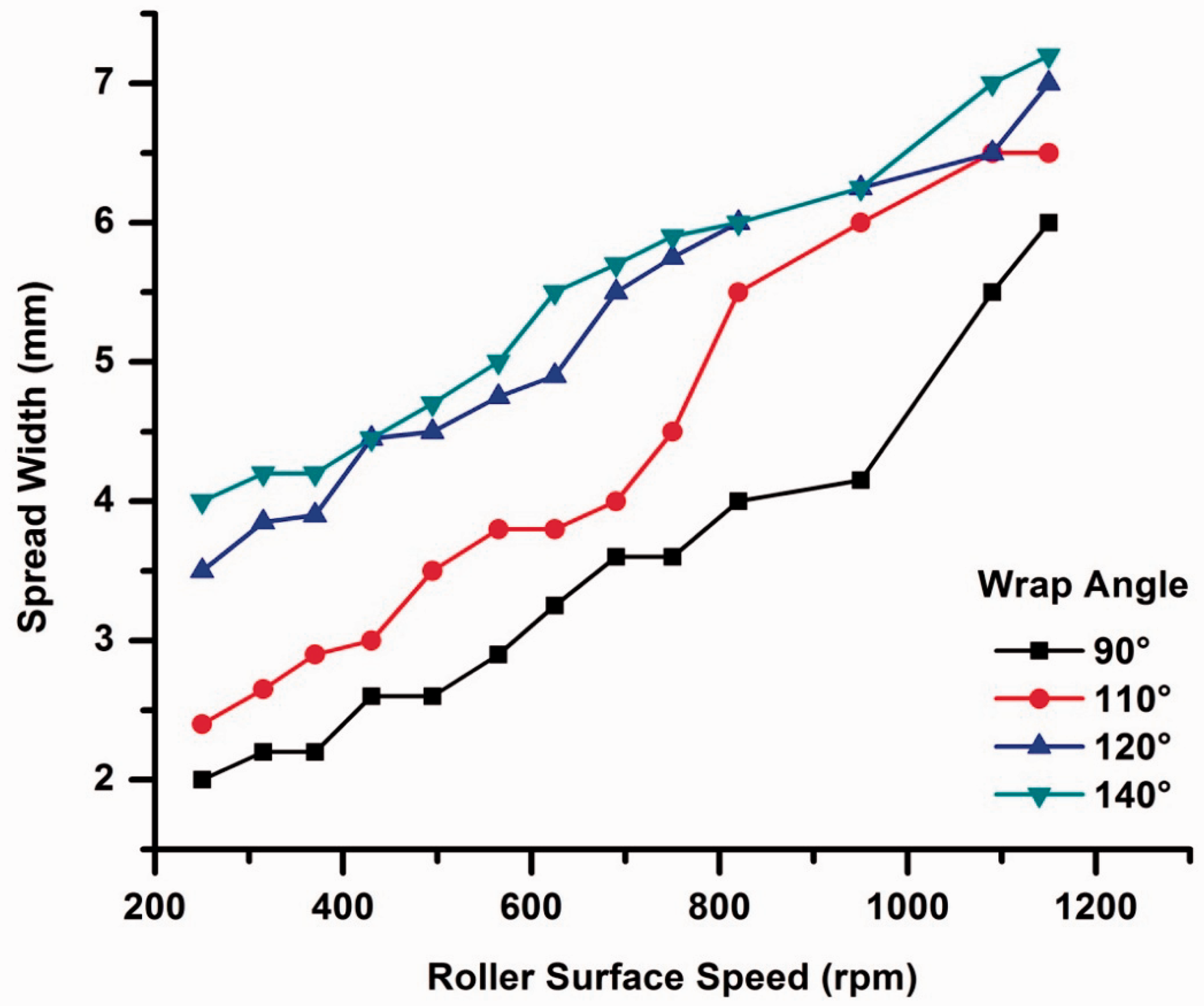
Effect of roller surface speed on spreading width
An increase in multifilament spreading width can be observed with increasing surface speed of the micro-grooved roller, as shown in Figure 6. This might be because of the fact that at higher roller speeds, a certain length of polyester multifilament more frequently comes in contact with micro grooves on the spreading roller surface. However, at higher roller speeds (i.e. above 800 rpm) some problems, such as excessive surface scratching of the multifilament, unstable position of the multifilament yarn on spreading roller and uneven spreading, were observed, which might be because of possible off-axis vibration of the grooved roller at excessive speeds. This vibration of the spreading roller will result in non-uniform spreading of the multifilament and, consequently, will worsen the yarn properties.
In order to analyze any decrease in polyester multifilament strength caused by surface scratching during the spreading process, we tested the breaking tenacity of 16.6 tex/36F multifilament yarns before and after spreading. F1 refers to the multifilament yarn fed from behind the nip of the front rollers and spun using the conventional ring frame. F2 refers to the multifilament strand spread by the micro-grooved roller before entering the nip of the front rollers and later wound on the bobbin using the modified ring frame. Surface speeds of 750 and 850 rpm were used, with a wrap angle of 140° between the multifilament and the grooved roller. Figure 7 shows that breaking tenacity and breaking extension (%) of F1 is better than F2, as can be expected. In addition, the mechanical properties of F2 decrease by increasing spreading roller speed from 750 to 850 rpm. This might be because of excessive scratching on the multifilament surface at higher speeds. However it was found that the scratching problem can be reduced to a certain extent by slight lubrication and smoothing of the micro-grooved surface.
Breaking tenacity and breaking extension (%) of F1 and F2 (at 750 and 850 rpm).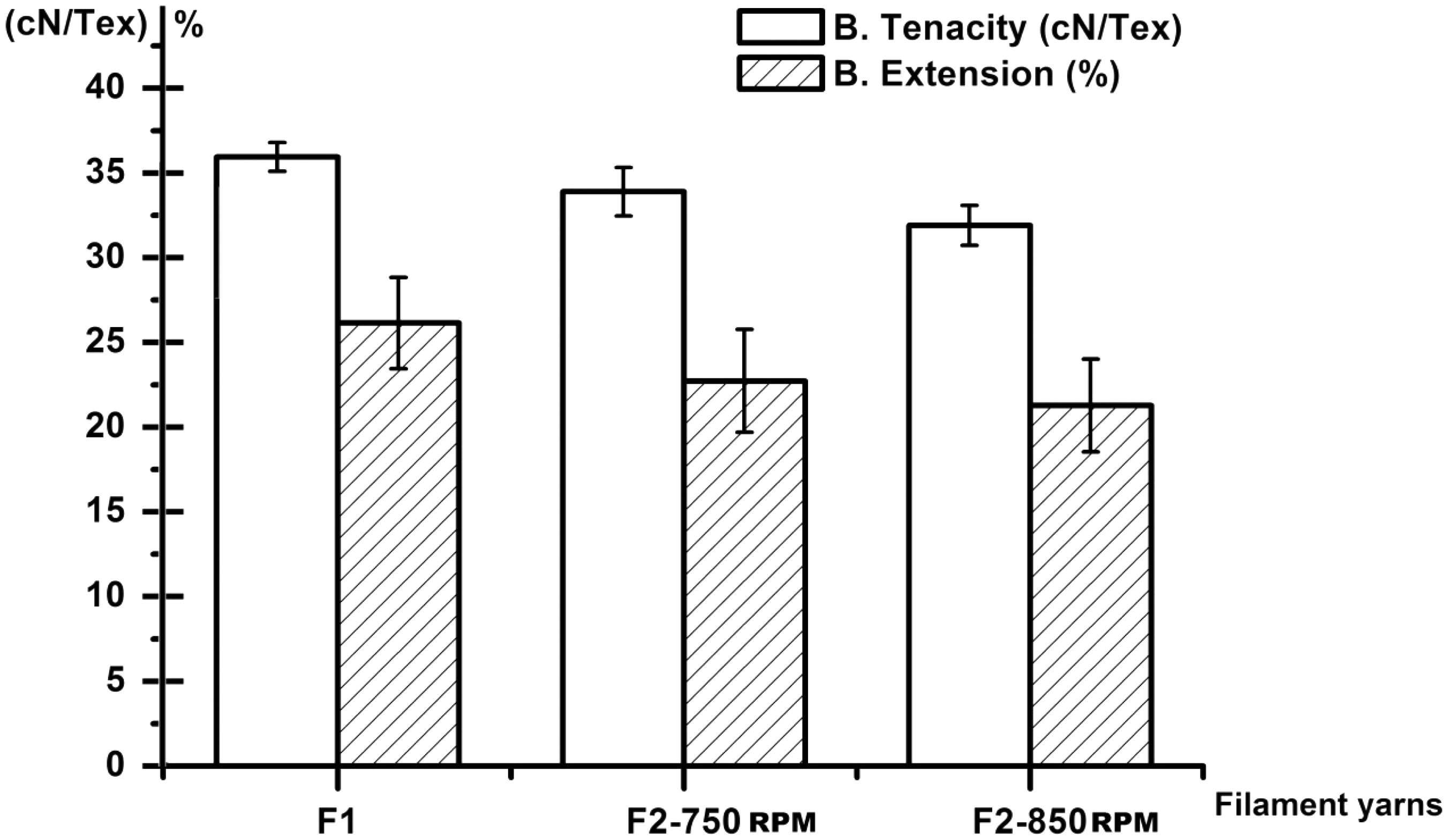
Size of micro grooves (dimensions)
Average width and depth of micro grooves were 10–12 and 12–15 µm, respectively, which are suitable for the average monofilament diameter (15–18 µm) used for this experimental work. Theoretically, it can be presumed that micro grooves’ width and depth must affect the multifilament spreading. If the micro grooves’ width and depth are larger than the monofilament diameter, more multifilament might move into a single groove during the spreading process, which will result in clustering and frequent breakage of the multifilament and ultimately hindering the smooth and uniform spreading, etc. Conversely, if the grooves’ width and depth is smaller compared to the monofilament diameter, little spreading will be achieved. Figure 8 shows the magnified SEM images taken to study the dimensions of micro grooves. If the size and dimensions of the micro grooves on the roller surface are not uniform, it would also be difficult to avoid narrowing and widening phenomenon during the spreading process. Ideally, smooth and uniform spreading can be achieved using identical-sized micro grooves.
Scanning electron microcopy image of the micro-grooved roller surface.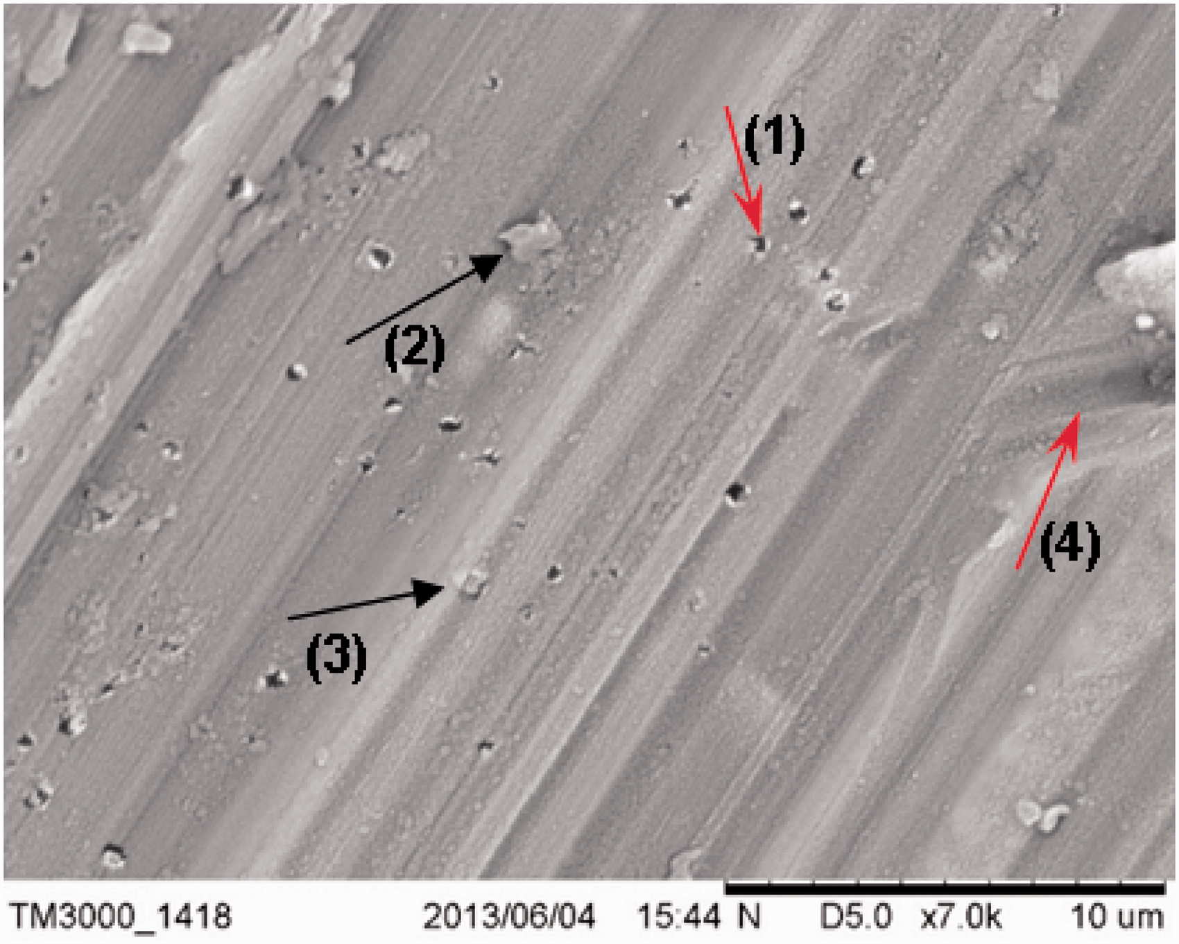
Figure 8 shows imperfections on the grooved roller surface, including micro pores (1), residual aluminum particles at root or depth (2), residual particles at the crest between two grooves (3) and intersecting grooves (4). These flaws result due to mechanical engraving, which limits the fabrication of entirely smooth and uniform grooves at the micro level. Hence these surface imperfections might damage the multifilament and affect the even spreading as well.
Micro pores (1) will have a minimum effect on the spreading process. Residual aluminum particles (2) at the root might disturb the uniform spreading, especially when the monofilament diameter is smaller than the groove width. Residual particles at the crest (3), however, can scratch the multifilament surface and disrupt the smooth spreading of the multifilament strand. Intersecting grooves (4) hinder uniform spreading and formation of the multifilament layer.
Scanning electron microscopy was used to analyze the surface morphology of micro grooves and any possible damage caused to the multifilament surface during the spreading function. Figure 9(a) shows the surface morphology of the polyester monofilament before coming in contact with grooved roller and Figure 9(b) shows the surface morphology after rubbing against the grooved roller surface. No special pattern of rubbing marks was seen on the monofilament surface; however, 2–3 µm long surface scratches were found along the length of the mono filament at random places.
Monofilament surface before (a) and after spreading (b).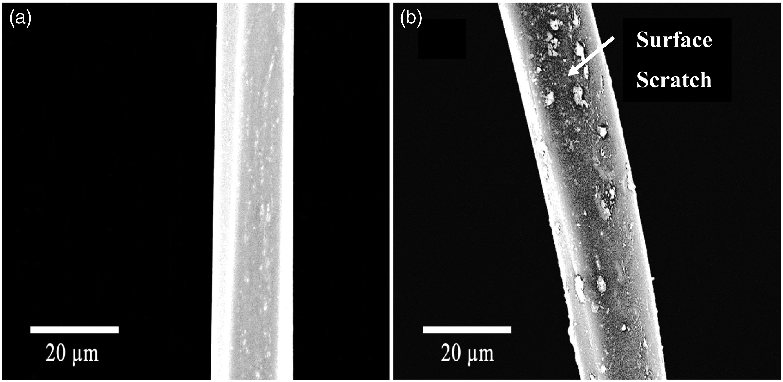
Effect on yarn properties
Two types of composite yarns were tested for breaking strength, breaking extension and hairiness. A total of 20 samples were tested for each type of yarn and the results are represented by relative stress and strain curves in Figure 10.
(a) Breaking tenacity and breaking extension curves for Y1. (b) Breaking tenacity and breaking extension curves for Y2.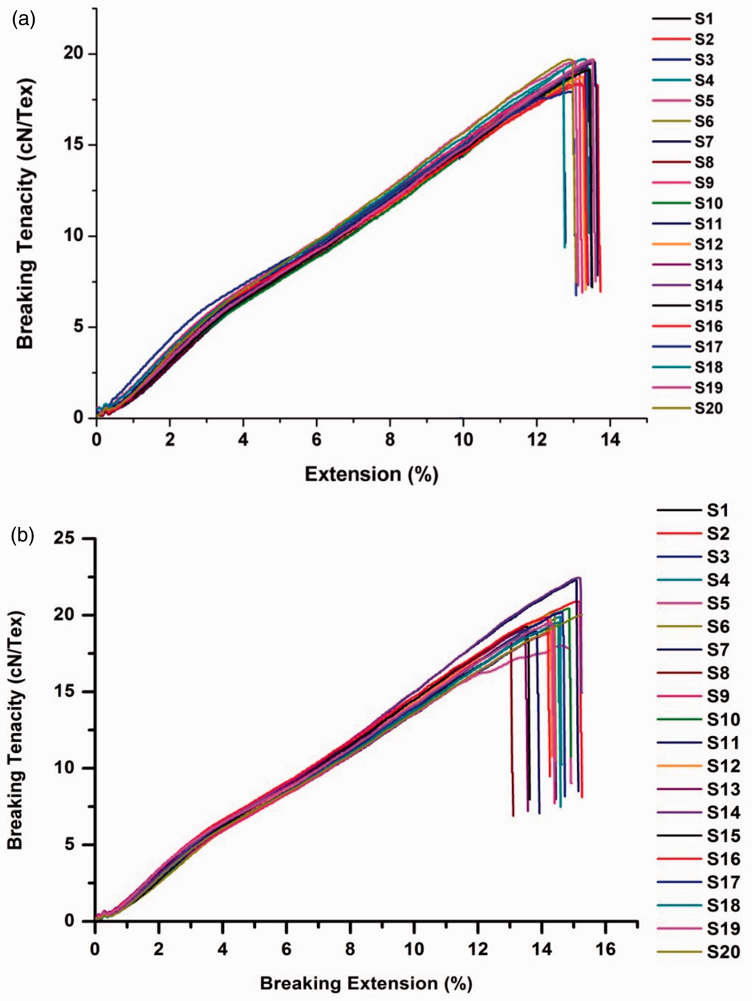
Tensile properties of yarn
The testing results of breaking strength for Y1 are shown in Figure 10(a), and for Y2 in Figure 10 (b). It was noted that the maximum breaking strength of Y2 reached 1088 cN; however, the breaking strength uniformity of Y1 was found to be better than that of Y2. The improved breaking tenacity of Y2 should be because of the even distribution of the multifilament and better multifilament wrap, which contribute to the yarn strength. Secondly, there is less chance of fiber slippage due to the tighter packing of staple fibers that improve the structure of composite yarn, so the cotton fibers also contribute the maximum interaction to increase in strength of the resultant composite yarn.
The inferior breaking strength uniformity of Y2 might be because of non-uniform wrapping of the multifilament layer, possibly due to narrowing and widening of the multifilament layer at certain places during yarn making and possible multifilament damage due to surface scratching during the spreading process. It was noted that due to friction and rubbing between the grooved roller surface and multifilament yarn, a few multifilaments might break sometimes during spreading process, which can be found sticking to the surface of the spreading roller after longer runs.
Table 1 shows that mean breaking tenacity and mean breaking extension for Y2 increased by 3.08% and 1.2%, respectively, compared to Y1, as shown in Figure 11(a), which help us to conclude that the wrapping of spread multifilament around the staple core contributes to improve the tensile properties of composite yarn. If the spreading width is uniform throughout the composite yarn spinning process, it might help to further improve the mechanical properties. The mean initial modulus values of Y2 were found comparable to Y1, as shown in Figure 11(b).
(a) Comparison of breaking tenacity and breaking extension (%). (b) Comparison of initial modulus for Y1 and Y2. Results of t-test and F-test analysis for Y1 and Y2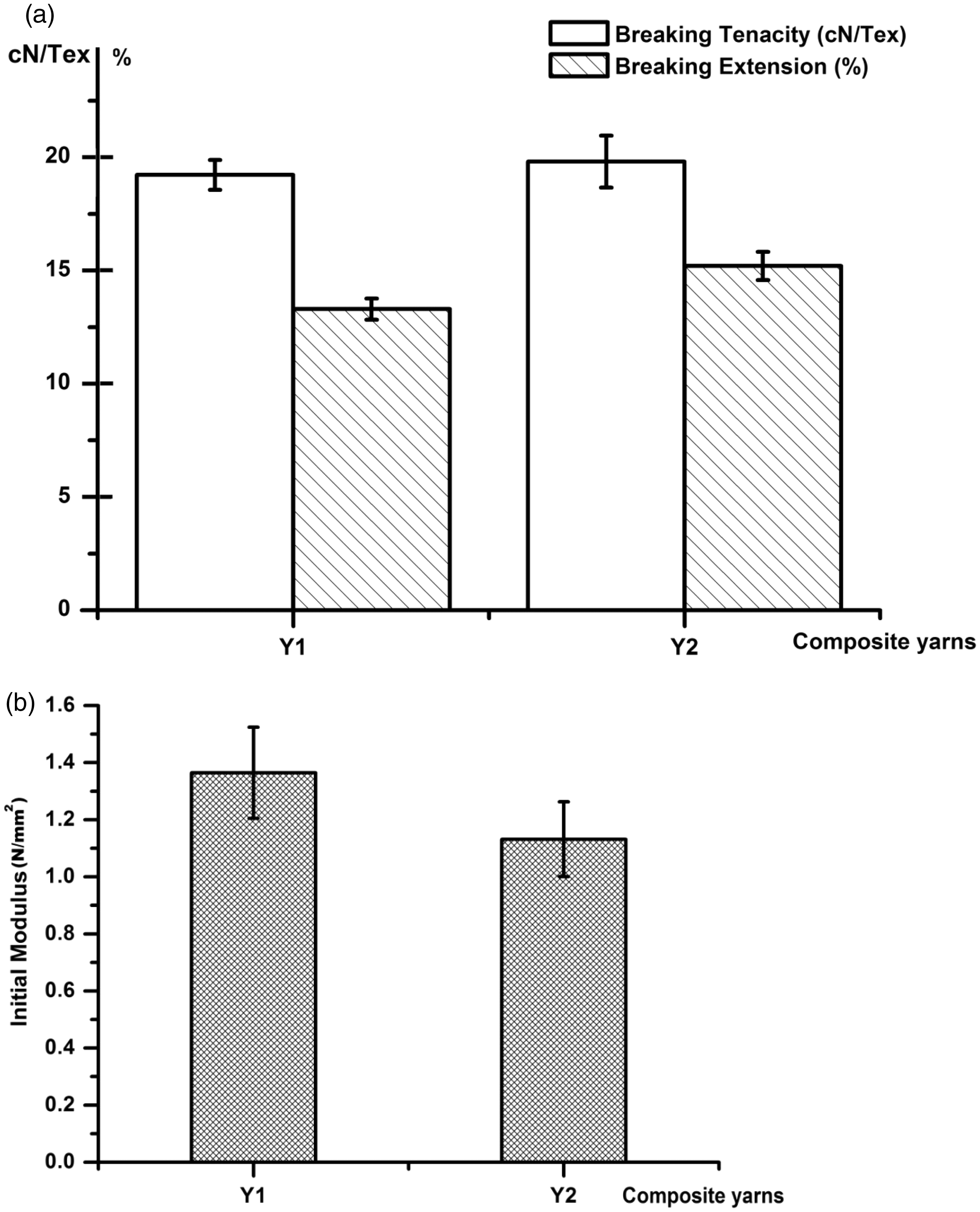

To determine the statistical significance of the difference of variance between two sets of data, an F-test was conducted (α = 0.05). According to the results given in Table 1, Fcalc (3.00993) for breaking tenacity is higher than Fcritical (2.16825), which states the difference in variance between two groups is statistically significant, whereas Fcalc (1.59767) for breaking extension percentage is lower than the Fcritical value. Hence, from the results of statistical analysis we can conclude that multifilament spreading might have affected the uniformity of the breaking tenacity of composite yarn. As mentioned earlier, the non-uniformity in breaking strength and breaking extension of Y2 might have resulted due to yarn unevenness caused by narrowing and widening of the multifilament layer during yarn making and surface scratching of the multifilament. These problems might be overcome by improving the groove formation technique and design of spreading roller assembly.
To statistically analyze any significance of the differences between mean values of breaking tenacity and breaking extension (%) of Y1 & Y2, a t-test (two samples assuming unequal variances) was performed at the 95% confidence level (α = 0.05). The tstat value (2.0024) for breaking tenacity is slightly lower than tcritical (2.0422), which states that mean value differences are not statistically significant. Since tstat (6.5107) for breaking extension percentage is higher than the tcritical value (2.0345), the means are statistically different, which supports our experimental hypothesis.
Yarn hairiness
Average hairiness measured for Y1 and Y2
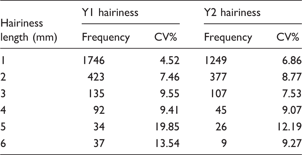
Figure 12 shows a typical longitudinal image of yarn samples taken using the Hi-Scope (KH-1000 MX 5030 RZ II) video microscope system. It is apparent that Y2 has a smoother surface and tighter appearance. Multifilament wrapping or covering ability around the staple core improved due to the spreading process, which helps to reduce the possibility of protruding fibers, and more fibers can be trapped inside the core of the yarn, resulting in improved packing of the composite yarn structure. To compare the multifilament wrap or cover ability around the staple core, associated wrap areas of a single turn were calculated for both Y1 and Y2. It was assumed that the yarn has a cylindrical shape and has fixed diameter (D), hence area = πDL. Figure 13 shows a schematic diagram of a multifilament wrap around the staple core, where L represents the multifilament layer’s wrapping breadth, and (U) is the area of complete turn. It was found that Y2 exhibits better multifilament wrap or cover (58.83%) compared to Y1 (37.91%).
Magnified longitudinal images of Y1 and Y2. Schematic diagram of the wrap yarn structure.

Conclusion
It can be concluded that the novel multifilament spreading method used for this research work is quite safe and commercially applicable. It does not have safety issues that are attributed to electrostatic spreading; it is also cost effective compared to the other spreading methods. It was found that micro grooves’ width, depth and angle are important for multifilament spreading. The surface speed of the spreading roller directly influences the spreading width; however, the smooth and steady rotation along the roller axis must be ensured to avoid the wide and narrow spreading effect. Tensile testing results demonstrate that even spreading of the multifilament positively influences the tensile properties of composite yarn. Composite yarns (Y2) made through the multifilament spreading method did not exhibit any significant decrease in breaking tenacity and breaking extension compared to the composite yarns (Y1) made using the conventional spinning method. Mean breaking tenacity and mean breaking extension for Y2 increased by 3.08% and 1.2%, respectively, compared to Y1 and the initial modulus decreased by 16.49%. Also, even spreading of the multifilament can help to effectively wrap the fibrous core, so that the fewer protruding fibers ends will be available at the yarn surface, which gives the resultant composite yarn a smoother surface and tighter appearance. The hairiness frequency of Y2 composite yarn was decreased by 24.78% compared to Y1 for 1–3 mm and 50.92 % for 4–6 mm. Although this method exhibited non-uniform spreading-related problems, which result in reduced breaking strength uniformity, advanced engraving techniques can be used to make fine identical grooves on the roller surface to overcome the associated spreading complications.
Footnotes
Funding
This research received no specific grant from any funding agency in the public, commercial or not-for-profit sectors.