



Abstract
Nanofiber filaments were produced by a home-made, multi-needle, liquid bath, electrospinning device, and the nanofiber alignment degrees of the filaments were investigated. The electrostatic fields of the multi-needle, liquid bath, electrospinning processes were simulated by the finite-element method, and an index, the average offset of the electrostatic field distribution in the needle tips, was established to quantify the existing electrostatic field interference. The effects of the number and the arrangement of the needles on the alignment degrees of the nanofibers and the breaking stress of the filaments were analyzed. The results showed that there was a linear negative correlation between the nanofiber alignment degrees and the number of needles with an R2 of 0.96. The larger average offset indicated the stronger electrostatic field interference, and a logarithmic positive correlation was determined between the average offsets and the number of needles with an R2 of 0.99. There was a linear negative correlation between the nanofiber alignment degrees and the average offsets with an R2 of 0.97. Meanwhile, when the average offsets in different numbers of needles increased from 0 to 0.160 mm, the average alignment degrees decreased from 0.964 to 0.774. Therefore, the optimal needle arrangement with the lowest average offset for each number of needles could be obtained. In addition, the breaking stress of the filaments decreased with the increase of the average offsets in the same number of needles, and the average breaking stress decreased initially with increasing the number of needles until three needles and then increased.
Keywords
Electrospinning is an efficient and straightforward technique to produce nanofibers from polymer solutions or melts under high-voltage, electrostatic fields.1,2 Compared with conventional fibers, nanofibers are characterized by high surface-to-volume ratios and flexibility;3,4 therefore, they have wide applications in biomedical engineering, electronic engineering and filtration fields.5,6 However, most electrospun nanofibers are collected in the form of nonwoven mats. The flaky and randomly-oriented structure and low mechanical strength of nanofiber mats have restricted their applications.7,8 In comparison with the nanofiber mats, nanofiber filaments or yarns formed by electrospinning can overcome these limits and expand the range of applications into the three-dimensional, nanofibrous, structure field. 9 Therefore, many methods have been developed to directly electrospin nanofibers into nanofiber filaments or yarns in recent years, 10 such as using the self-assembly, 11 the dual electrodes, 12 the air assistant twisting device, 13 the liquid bath collector14,15 and the rotary intermediate collecting device.10,16,17 In our previous studies, the nanofiber filaments could be continuously spun by the liquid bath, electrospinning technique. 18 Khil et al. 19 weaved filaments manufactured by this liquid bath, electrospinning method into plain fabrics and investigated their biomedical properties. Li et al. 18 an Liu et al. 20 improved this electrospinning method through adding a drying device, and researched the morphology, mechanical and electrical properties of the as-spun filaments manufactured by the method.
However, there is an apparent disadvantage in using the filament produced by liquid bath electrospinning with a spinneret: the low production rate has limited its industrial use. 21 Multi-needle electrospinning can overcome this low production issue, 22 but only if the electrostatic interference between needles can be well controlled. Yang et al. 21 simulated a two-needle, electrospinning process using the finite-element analysis method and found that the electrostatic field interference decreased with increasing the distance between needles. Tomaszewski et al. 4 researched the electrospinning process using three types of needle arrangements (series, elliptic and concentric) and proved that the concentric arrangement was the best with regards to both the electrostatic field interference and the efficiency. Theron et al. 23 investigated the nine-needle (arranged in 3 × 3 and 9 × 1 arrays), electrospinning process and found that the electrostatic field interferences of the side needles were larger than those of the central needles.
However, all these studies provided few quantitative methods to analyze the electrostatic field interference. According to the electrostatic field theory, there are many factors affecting multi-needle electrospinning, such as spinning voltage, flow rate, spinning distance, electrostatic field interference, etc. However, the most important factor is the electrostatic field interference. The main purpose of this paper was to study the effect of the electrostatic field interference on multi-needle electrospinning. Therefore in this article, a home-made, electrospinning device was used to manufacture nanofiber filaments, and the effects of the number and arrangement of the needles on (1) the alignment degrees of the nanofibers and (2) the breaking stress of the filaments were evaluated. Meanwhile, an index was established to quantify (1) the existing electrostatic field interferences and (2) the effect of the electrostatic field interferences on the alignment degrees of the nanofibers and the breaking stress of the filaments, with the purpose of producing high-alignment degree, nanofiber filaments using the multi-needle, liquid bath, electrospinning process. And this paper also gave a way to find the optimal needle arrangement for each number of needles, which could provide both theoretical and technological bases for the multi-needle, electrospinning process. Based on the research above, other factors, such as spinning voltage, flow rate and spinning distance, will also be studied in our future research.
Experimental
Materials
Pure PA6 pellets (Sigma Aldrich Inc.) were added into an 88-wt% formic acid solution (Shanghai Chemical Reagent Co., Ltd), and the mixture was uniformly mixed by vigorous stirring at room temperature. The concentration of PA6 solution was 25 wt%. The bath, 0.5 wt% Peregal O solution, was prepared by dissolving Peregal O (Jiangsu Jiafeng Chemical Co., Ltd) into deionized water at room temperature. 18
Filament manufacture
The nanofiber filaments were manufactured by a self-made, multi-needle, liquid bath, electrospinning device, as shown Figure 1. The electrospinning solution was placed into a 20 ml glass syringe (inner diameter (ID) = 20.84 mm), and then drawn to the distributor (made of stainless steel) by the extrusion of the syringe pump. After the uniform distribution, the solution arrived at the spinneret plate, which consists of needles (arranged as shown in Table 1, ID = 0.1 mm) and a needle supporter. The needles in the spinneret plate were connected to the cathode of the high power supply by a copper wire (outer diameter (OD) = 0.38 mm) and the anode was inserted into the bottom of the bath reservoir (ID = 200 mm), thereby enabling the formation of a high-voltage, electrostatic field, thereby turning the solution into nanofibers on the surface of the bath. The nanofibers on the surface of the bath were initially drawn out by a long glass rod; meanwhile the nanofibers began to assemble into a wet nanofiber bundle with the help of the bath. With the guidance of the glass rod, the wet nanofiber bundle passed the guide roller, the heater and the tensile guide equipment at a certain speed, successively, and finally the nanofiber filament was wound on the rotation mandrel. Then under the drawing force caused by the rotating of the mandrel, the nanofiber filament was continuously manufactured.
Schematic diagram of the multi-needle, electrospinning device. Needle arrangements for one–five needles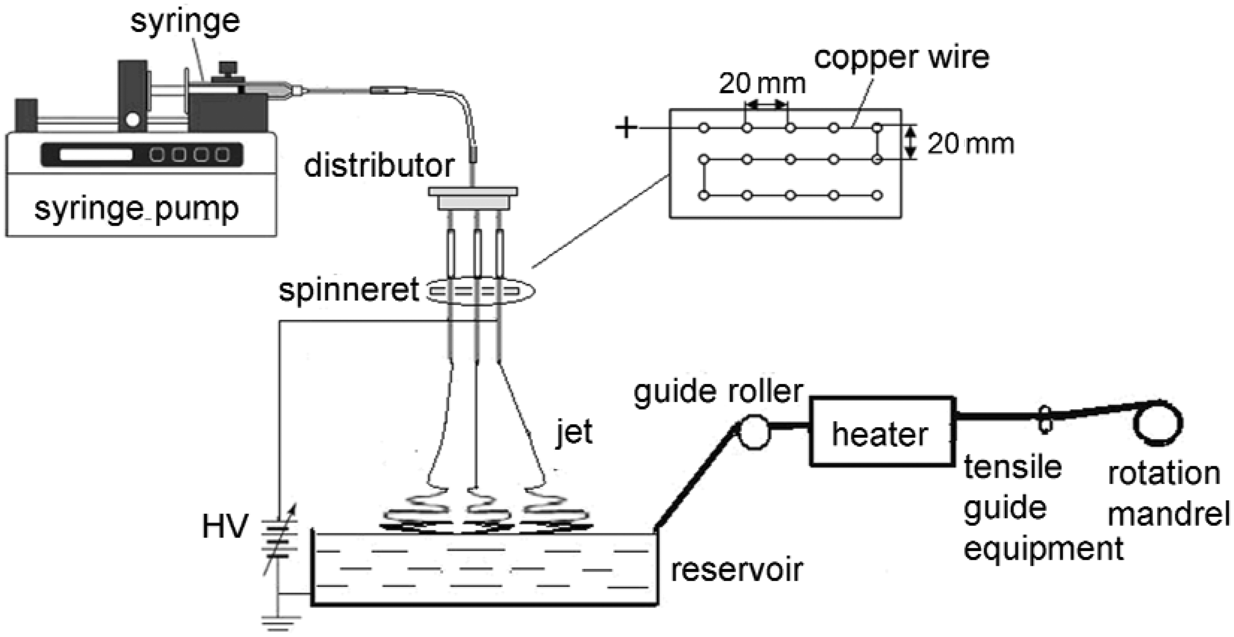


The constant electrospinning parameters in the multi-needle, liquid bath, electrospinning process were set as follows: the flow rate was 0.1 ml/h per needle, the voltage was 26 kV, the vertical distance from the needle tip to the bath surface was 60 mm, the length and temperature of the drying device was set at 200 mm and 350℃ respectively, and the diameter and the speed of the rotation mandrel was 78 mm and 588 m/h, respectively.
Characterizations
The morphology of the longitudinal surface of each of the nanofiber filaments was investigated by a scanning electron microscope (SEM) (Hitachi S-4800).
The nanofiber alignment degrees of the filament were calculated by an image analysis software (Image Pro Plus 5.0). This quantification process is summarized in Figure 2. First, the total area of the filament in one SEM image was measured and defined as S’i; next, the areas of the nanofibers parallel to the filament axis, such as Si
1
, Si
2
…Sij, were measured; and then five SEM images in different areas of the same filament were used to obtain the nanofibers alignment degree (od) of the filament as equation (1). Finally, the average alignment degree ( Schematic diagram of the nanofiber filament.
Ten tensile tested samples were selected randomly from the tested filament spun in a certain needle arrangement, and each sample was 50 mm long. The diameters of each sample (di) were characterized by the mean values of 10 times measurements by a CU-2 fiber fineness tester with a DMLP optical microscope (Leica). The breaking strength (Fi) of each sample, which had been kept at standard conditions (20 ± 2℃, 65 ± 2%RH) for 24 h before testing, were tested by Instron 3365, with the constant parameters of: gauge length of 10 mm, crosshead speed of 10 mm/min, initial tension of 0.1 cN, and strength and elongation resolution of 0.01 cN and 0.01 mm, respectively. The breaking stress of each nanofiber filament (δ), which was the mean value of the breaking stress of the 10 samples, was calculated according to
Results and discussion
According to the conventional textile theory, the alignment degree of the fibers parallel to the yarn axis is a key factor to a yarn, which influences its structure and property. Because the conventional textile theory is also suitable for the nanofiber filaments, the alignment degree of the nanofibers parallel to the filament axis is expected to be a key factor here.
The nanofibers alignment degrees (od in equation (1)) of the filaments (Figure 3) that were spun by two–five needles with different needle arrangements are shown in Figure 4. The results indicated that both the overall alignment degrees and the maximum alignment degrees in each group presented a decreasing trend with increasing needles. Figure 5 indicates that the average alignment degree (equation (2)) decreased with the increase of the needles, and that the fitting curve exhibited a linearly decreasing trend, with the regression equation of The SEM images of the two–five needle, electrospun filaments: (a) two needles, (b) three needles, (c) four needles and (d) five needles. The alignment degrees of the filaments spun for different needle arrangements. The average alignment degrees of one–five needle, electrospun filaments.
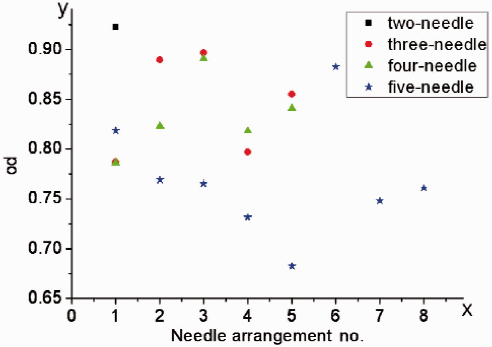
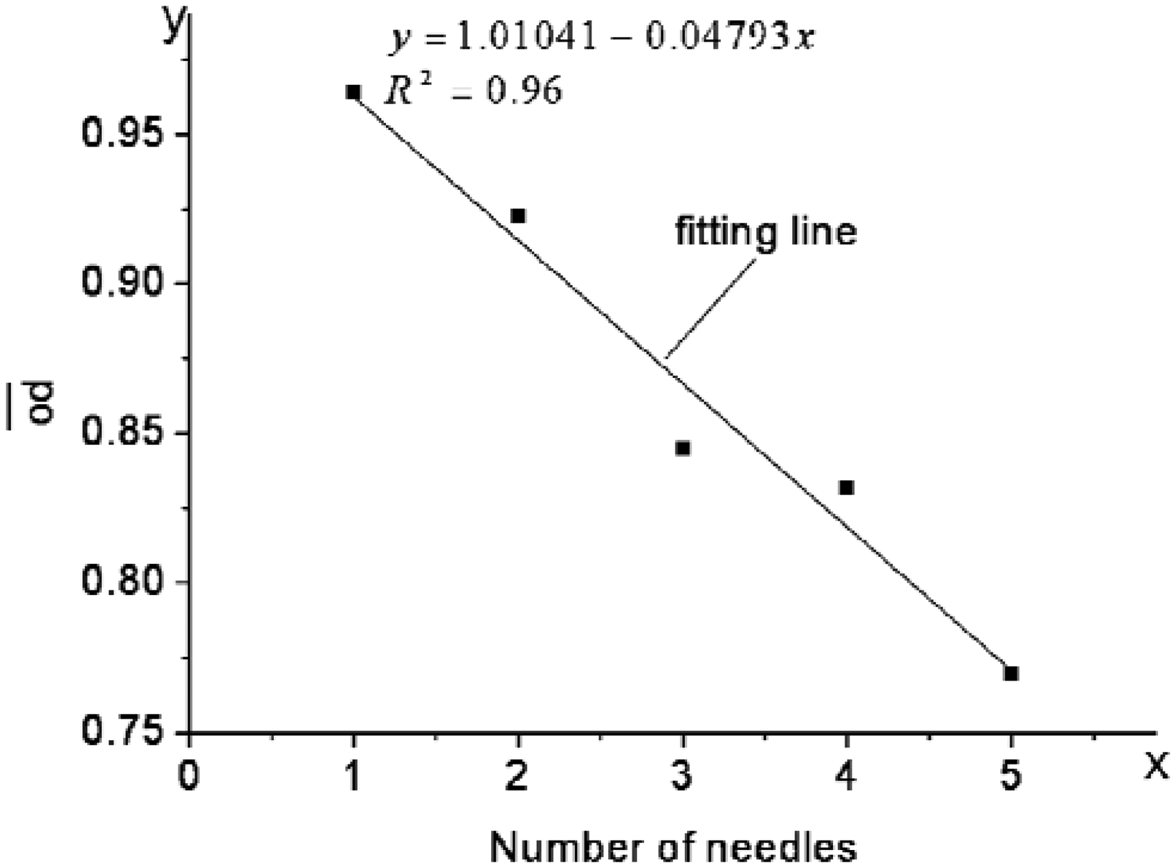
According to the results in Figures 4 and 5, the alignment degrees significantly varied when using different numbers and arrangements of the needles. Because other parameters were fixed, the variations of the alignment degrees could be only caused by the changes of the numbers and arrangements of the needles, which changed the overall electrostatic field interferences. In order to specify the effects, a novel method must be used to quantitatively analyze all the electrostatic field interferences.
Simulation and quantification
The existence of electrostatic field interference in the multi-needle, electrospinning process has been proven by electrical theory. To study this interference and to explore its effect on the as-spun, nanofiber filament, a software (Ansoft Maxwell 13) based on the finite-element method was used for the electrostatic field simulations and calculations. Figure 6 shows examples of the electrostatic field simulations performed by Ansoft Maxwell, with all the parameters in the simulation setup at the same values as those in the experiment except the copper wire. As the connection forms and positions of the copper wires in different needle arrangement conditions were all the same, the effects of the copper wires on the overall electrostatic fields were all the same too. Meanwhile, as the copper wire is located far away from the needle tips, the influences of the copper wire on the electrostatic fields in the needle tips were quite weak. Therefore, the influence of the copper wire on the overall electrostatic field could be ignored, and it could be omitted in the simulation. From the simulation results, the entire electrostatic field distribution in the multi-needle, electrospinning space could be observed clearly, and the electrostatic field was found to become weaker from the needle tips to the surface of the liquid bath. Because the electrospinning process was highly dependent on the electrostatic field, particularly the local field at the needle tip, whose interference determined the behavior of the electrospinning process,
24
the electrostatic fields at the needle tips must be accurately calculated.
The electrostatic field simulation diagrams of the multi-needle, electrospinning process: (a) the scale of the simulation diagrams, (b) one needle, (c) two needles, (d) three needles, (e) four needles and (f) five needles.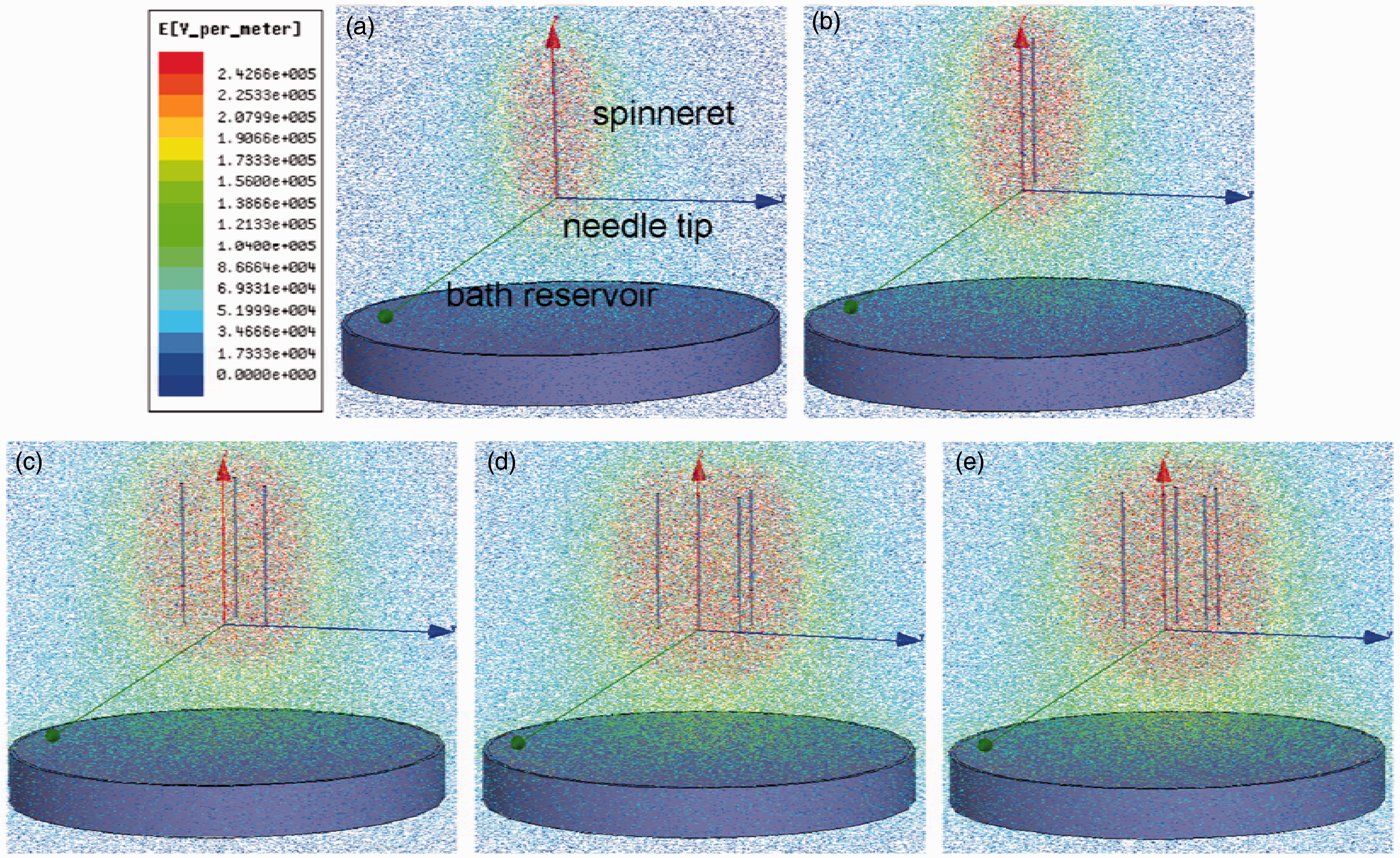
However, the common results of the electrostatic field simulations of the needle tips, such as that shown in Figure 7(a), could only provide vague results. Therefore, an index was established to obtain the quantitative electrostatic field interference value at the needle tips. The quantification process was shown in Figure 7. First, the cross-section of each needle tip (tiny black spot in the middle of the red circle) was simplified into a circular area, and then the tip were evenly divided into 36 parts, i.e. the included angle between each adjacent cut-off line was 10° (as shown in Figure 7(b)). Second, the electrostatic field values were calculated along the radius of each tip from the center to the vertex of the circle by Ansoft Maxwell, and then a certain average electrostatic field value was drawn as a point at the corresponding radius in the circular area. Finally, all the points were connected to form an electrostatic field distribution map at the needle tip (as described in Figure 7(c) and Table 2).
The quantification process: (a) the electrostatic field simulations of the needle tips, (b) the cross-section of each needle tip and (c) the electrostatic field distribution map. The electrostatic field distribution map at the needle tip of each of the needle arrangements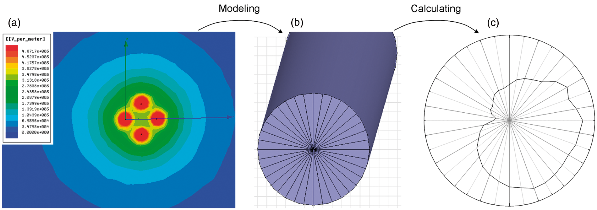


In the one-needle, electrostatic field simulation, the center of the electrostatic field distribution map was just the center of the circle, while the centers of every electrostatic field distribution map deviated away from the center of the circle in the multi-needle, electrostatic fields. This shift was obviously the result of the electrostatic field interference in the multi-needle, electrospinning process. The offset (as described in equation (4)) of the electrostatic field distribution map center from the circular center could be used to quantify the intensity of the electrostatic field interference, and the larger offset should indicate the larger electrostatic field interference.
In order to obtain the quantitative method of the overall electrostatic field interference, the relationship between the average offset (ao in equation (5)), which was the average result of all the needles in a certain needle arrangement, and the distance between the needles was studied. According to the electrostatic field theory, the overall electrostatic field interference decreased with the increase of the distance between needles,
21
and Figure 8 shows the average offset also decreased with the increase of the distance between the needles in all the two–five needle, electrospinning processes. Therefore, the overall electrostatic field interference could be quantified by the average offset. We have
The relationship between ao and distances between needles in the two–five needle, electrospinning process: (a) presented the third needle arrangement in the three-needle, while (b) showed the third needle arrangement in the four-needle and (c) the sixth arrangement.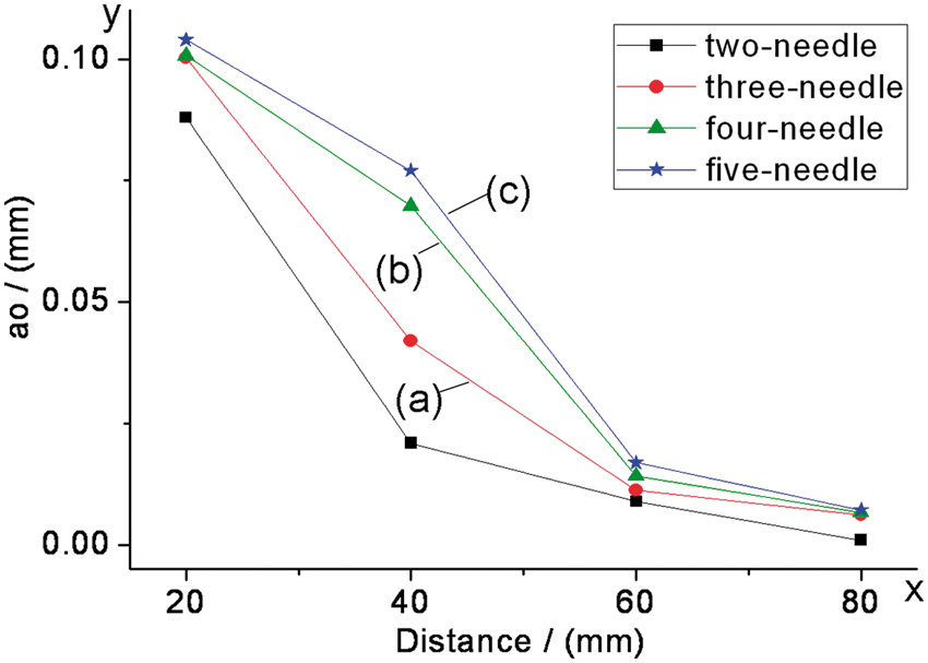
Effect of the needle arrangement on the nanofiber alignment degree of the filament
The results of the average offsets for different needle arrangements of two–five needles in the electrospinning processes are shown in Figure 9. Compared with the overall interferences in the different needle arrangements, as shown in Figure 10, the nanofiber alignment degrees of the filament spun by different needle arrangements were obviously inversely proportional to ao, and the decreasing trend was in linear form, with the regression equation The average offsets in the electrospinning process for different needle arrangements. The relationship between ao and od. The SEM images of the filaments spun in different needle arrangements of five needles: (a) the first arrangement and (b) the fourth arrangement.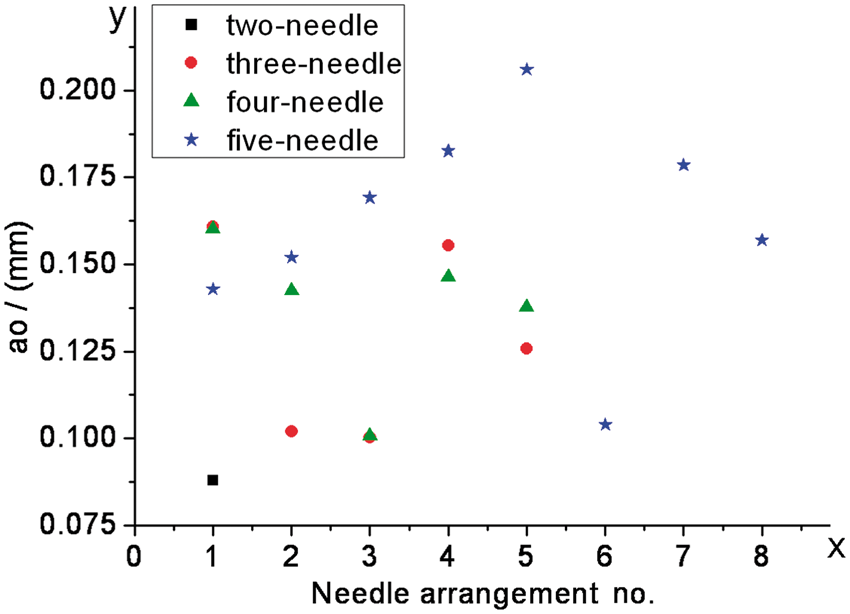
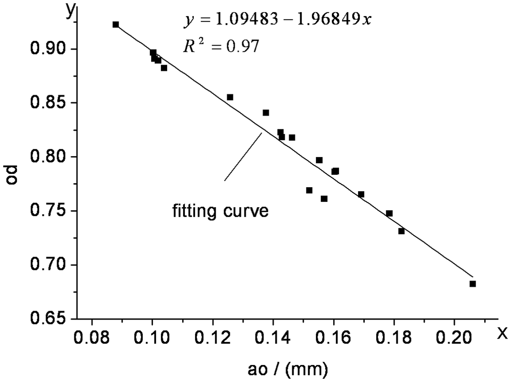
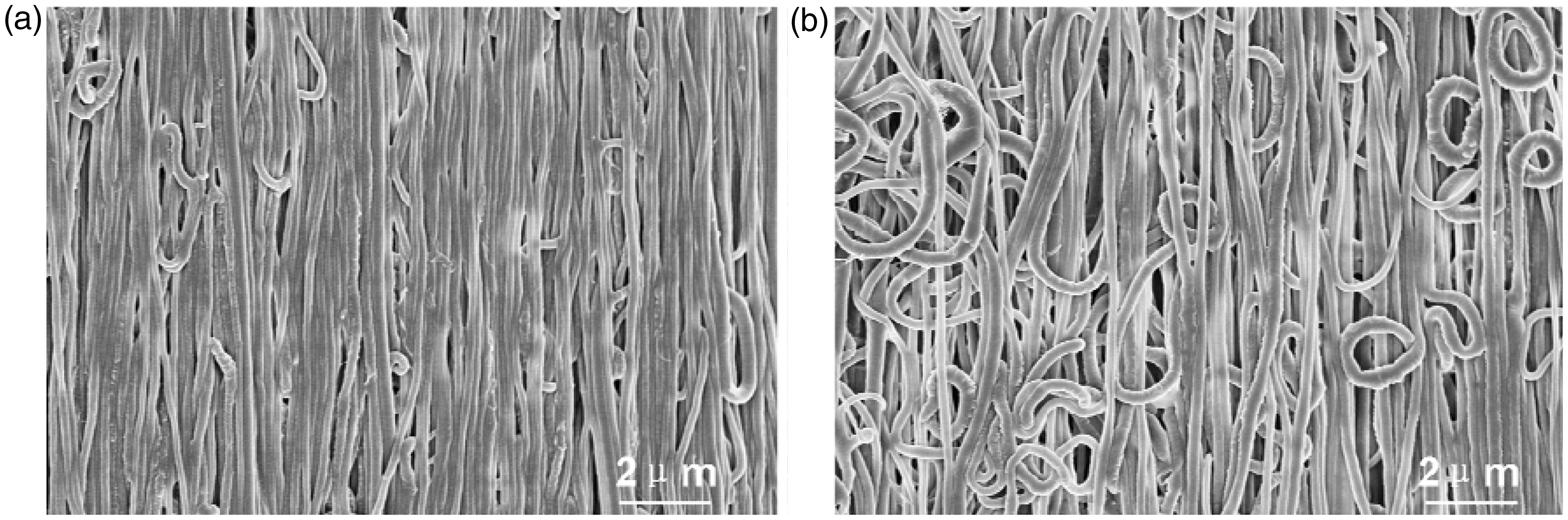
As a result, the optimal needle arrangement that resulted in the best alignment degree for each number of needles could be obtained from this method, i.e. the needle arrangement with the smallest ao in each number of needles obtained from the index. The ten-needle, electrospinning system was taken as an example to verify the index. The needle arrangement of the lowest ao value of ten needles (ao = 0.158) was obtained through this method; the alignment degree testing results showed that the best alignment degree (od = 0.789) nanofiber filament was produced by the lowest ao value needle arrangement. Meanwhile, the best alignment degree of ten needles was higher than most alignment degrees of five needles.
Effect of the number of needles on the nanofiber alignment degree of the filament
The average offsets in the different numbers of needles ( The average offsets in the one–five needle, electrospinning process.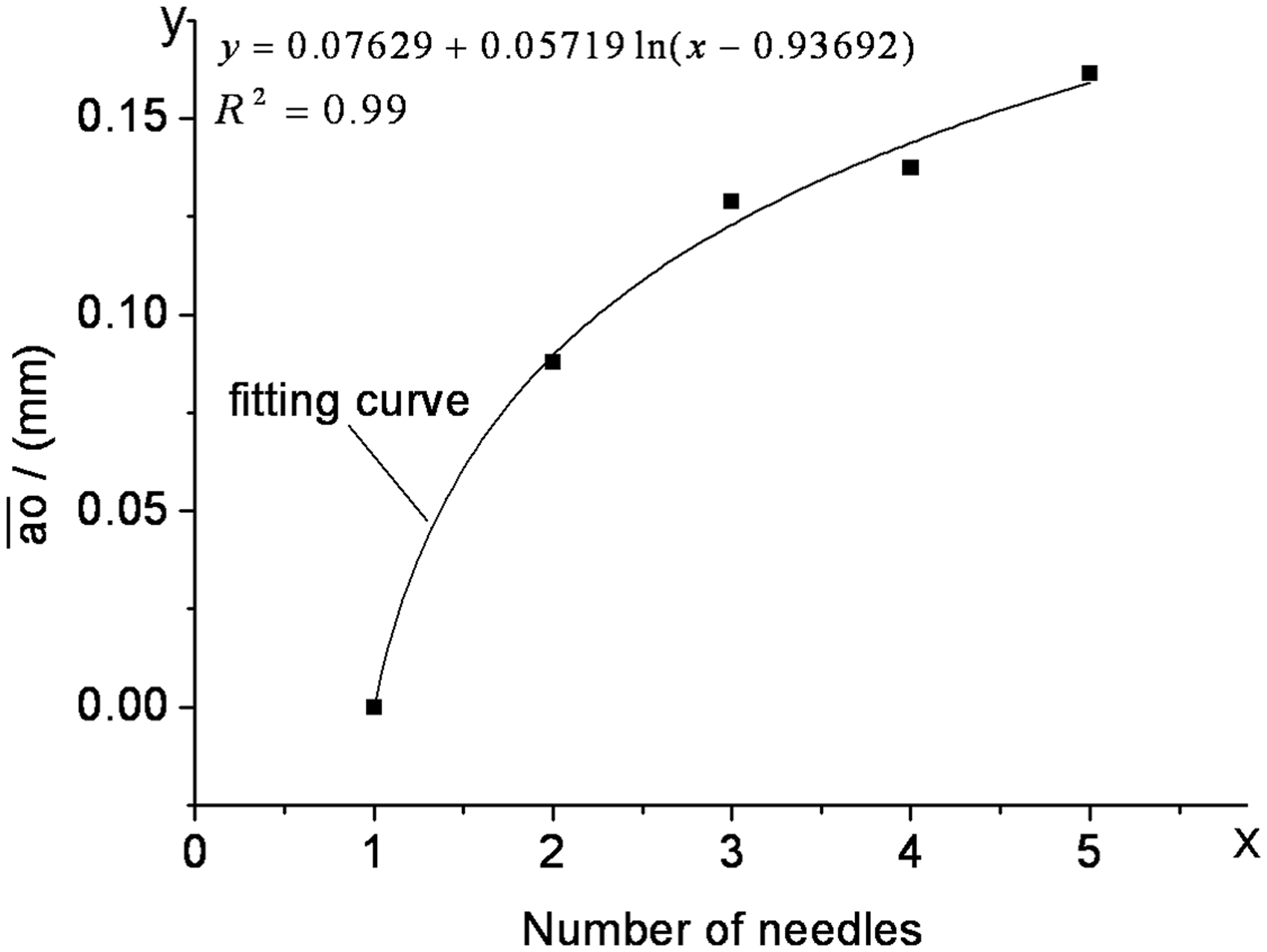
Effect of the needle arrangement on the breaking stress of the filament
The breaking stress of the filaments spun by different needle arrangements of five needles

Effect of the number of needles on the breaking stress of the filament
Figure 13 shows the effect of the number of needles on the tensile breaking stress of nanofiber filaments. The average breaking stress ( The average breaking stress of the filaments spun by one–five needles.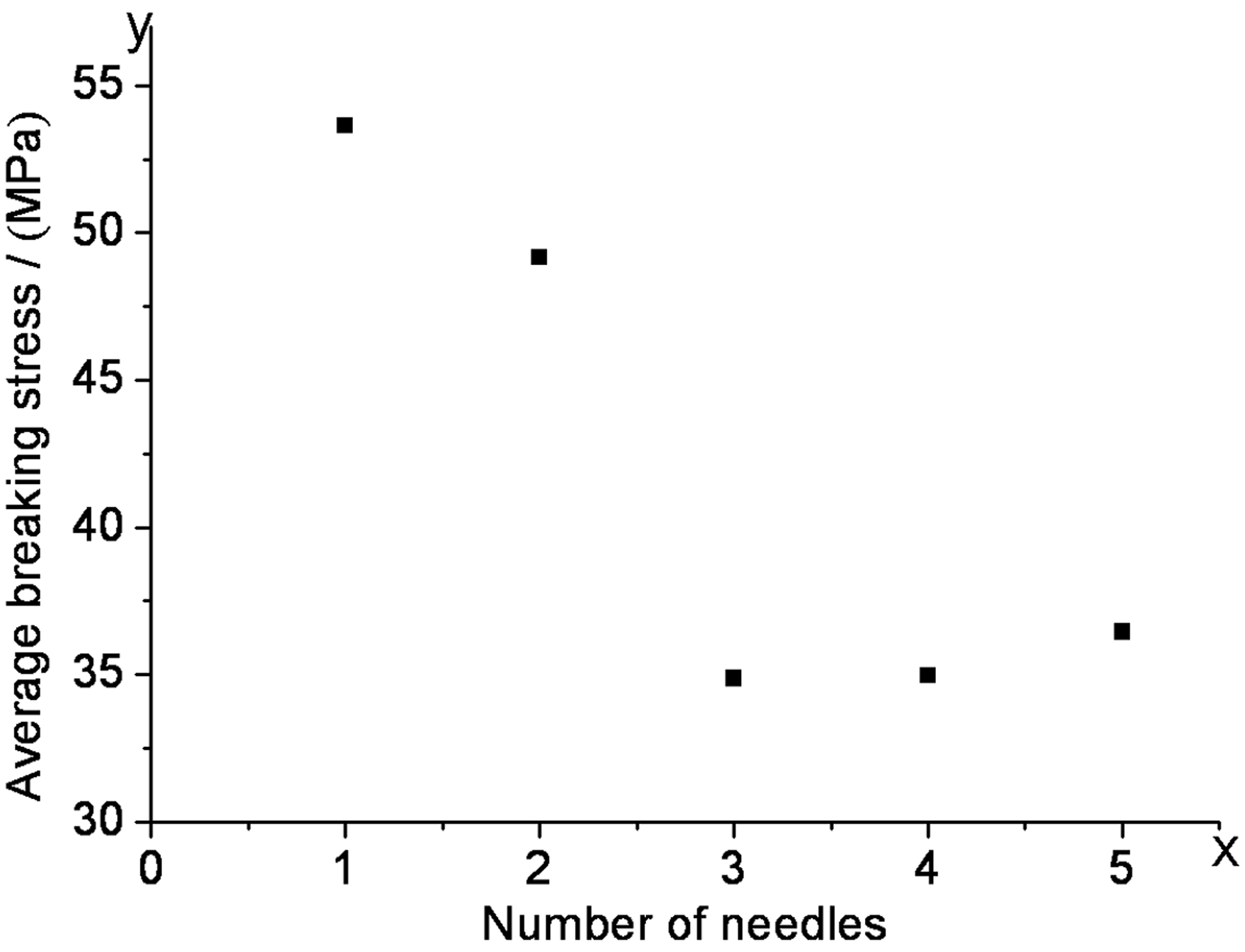
Conclusions
In this paper, PA6 nanofiber filaments were manufactured by the multi-needle, liquid bath, electrospinning technique. The nanofiber alignment degrees of the filaments were characterized by the area ratio of the nanofibers that arranged parallel to the filament axis to the total nanofibers, and a linear negative correlation was found between the nanofiber alignment degrees and the number of needles, with an R2 of 0.96. The simulations of the multi-needle, electrospinning, electrostatic fields were performed by software, Ansoft Maxwell, and an index was established to quantify the overall electrostatic field interferences using the average offsets of the electrostatic field distribution in the needle tips; the simulation results showed that the larger average offset indicated the stronger electrostatic field interference, and there was a logarithmic positive correlation between the average offsets and the number of needles with an R2 of 0.99. Finally, a linear negative correlation was determined between the nanofiber alignment degrees and the average offsets with an R2 of 0.97. Meanwhile, when the average offsets for different numbers of needles increased from 0 to 0.160 mm with the increase of the number of needles, the average alignment degree decreased from 0.964 to 0.774. Therefore, the optimal needle arrangement with the lowest average offset for each number of needles could be obtained, and this index could be extended to apply in multi-needle electrospinning. In addition, the breaking stress of the filaments decreased with the increase of the average offsets for the same number of needles, and the average breaking stress decreased initially with increasing the number of needles until three needles and then increased.
Footnotes
Funding
Financial support for this work was provided by the Nanotechnology Special Project of the Suzhou Science and Technology Program Project (ZXG2012043) and the Priority Academic Program Development of the Jiangsu Higher Education Institutions.