




Abstract
In extreme weather conditions and activity levels of human subjects, evaporation of sweat is critical for maintaining the sensorial and thermal comfort. Fabrics, from which clothes worn next to the skin are made, play an important role in facilitating the transfer of body liquid perspiration away from the skin to the environment through the mechanisms of capillary flow and evaporation. This work is a theoretical and experimental investigation of water flow characteristics of yarns with relevance to their structure geometry and constituent fiber chemistry.
A theoretical model to predict the capillary flow of liquid water through yarns was proposed. The model is based on the Kozeny–Carman equation, which represents interfiber pores in terms of the hydraulic radius theory. Cotton, polyester and cotton/polyester yarns were produced by systematically varying different production parameters, including fiber type, yarn twist, yarn linear density and blend ratio. Plain knitted fabrics were produced and yarns taken from the produced fabrics were tested for horizontal linear flow of liquid water. The experimental results showed a strong correlation with the estimated results based on the theoretical model. The model predicts that as the ratio of interfiber pore space area to the total fiber perimeter within yarn increases, the flow rate is expected to increase.
Efficient transfer of body moisture is a critical performance criterion of knitted fabrics used in next-to-skin clothing. In hot conditions evaporation of sweat becomes the main avenue for heat loss to the environment and is found to account for 80% of total body heat loss during exercise.
1
It was established that the physiologic mission of sweat can only be achieved when it evaporates from the skin surface or from the next-to-skin clothing layers.2,3 The vapor carries with it the latent heat of evaporation, which is the equivalent heat loss for evaporating a given quantity of water. The speed at which liquid water travels across the fabric plane is a critical property that characterizes next-to-skin clothing fabrics with efficient sweat transfer performance. Yarn structure, which is an assembly of fibers aligned in parallel, is the basic element of knitted fabrics. The air space within the yarn, referred to as interfiber pores, exerts capillary pressure force, which drives liquid through the fabric. Understanding the theoretical basis of capillary flow through yarns in relation to fiber and yarn structure parameters allows engineering of fabrics with predetermined liquid transfer properties. Capillary-driven flow applies to liquid not held in solution and to all moisture above fiber saturation point and equilibrium regain, at the standard testing atmosphere for textiles (20℃, 65% relative humidity (RH)). The capillary action is a suction force that draws the liquid through the fabric structure it is in contact with under no externally applied pressure.
3
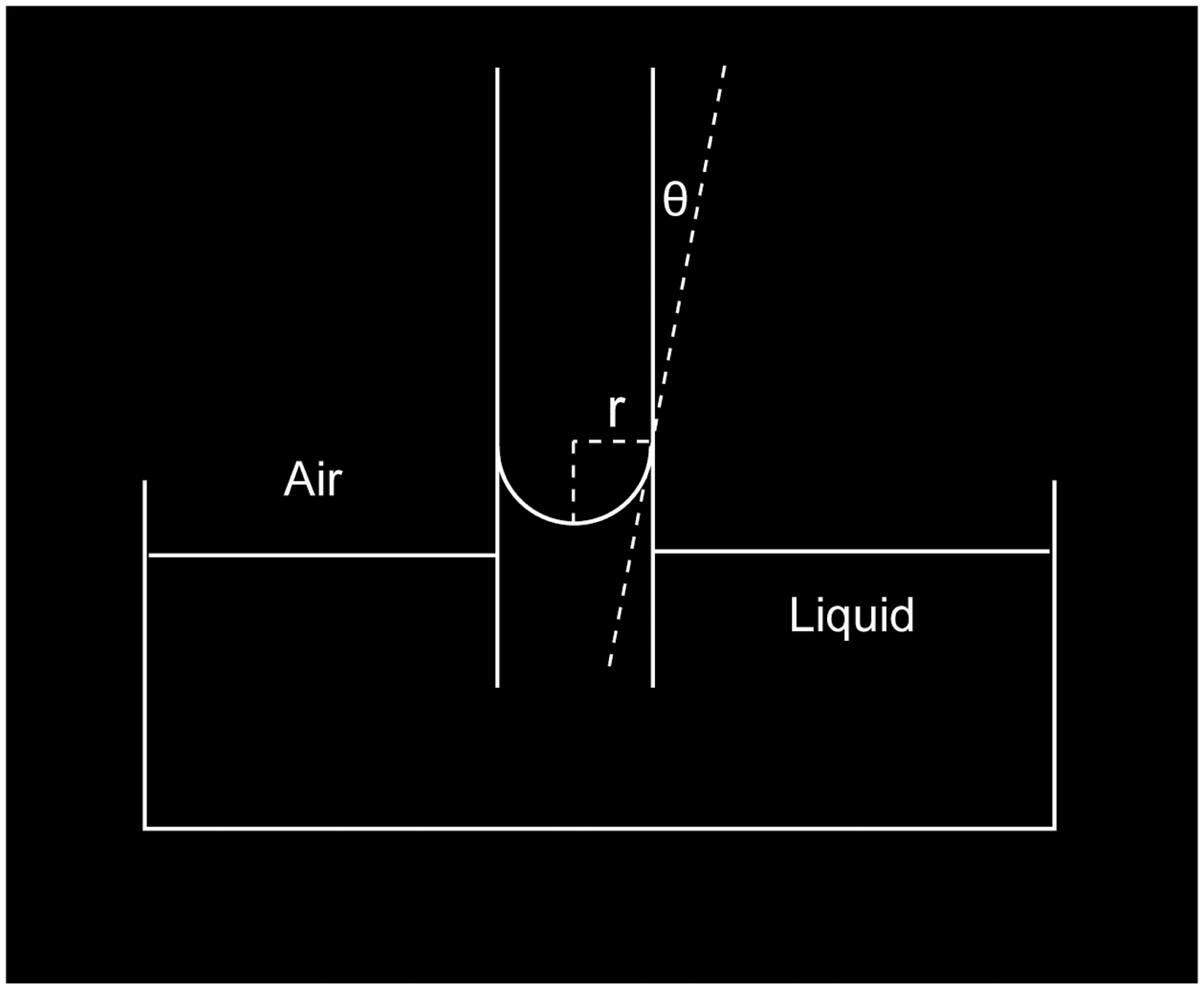
The phenomenon is synonymous with the fabric “wicking” performance. The magnitude of the capillary pressure is commonly described through the well-known Laplace equation, which applies to idealized capillary tubes (Figure 1) as follows:
4
Liquid rise in a capillary tube (adapted from Schwartz
5
).
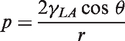
The rate at which liquid is driven through a cylindrical tube via capillary action is traditionally calculated by the well-established Lucas–Washburn equation. The relation was derived from Hagen–Poiseuille’s law by balancing viscous and capillary forces and neglecting gravitational and inertial forces to give the relation
6
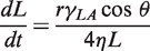
Integrating leads to
6
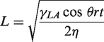
According to the Washburn equation above, it is clear that the capillary radius is a critical geometric parameter that determines the capillary-driven flow rate within the channel. Analogous to flow through capillary tubes, the equation has been widely used and further developed to characterize the influence of material and geometric parameters on the capillary-driven water flow through yarns. In such applications pores within yarn, known as interfiber pores, have been represented in terms of an equivalent average pore radius using geometric models.7–9 The yarn idealized packing model presented by Hearle et al. 10 has been adopted in those models. Treating pores within fibrous structures as idealized capillary tubes is among the many limitations of the Washburn equation, as summarized by Zhuang et al. 11 For yarns in particular, interfiber pores do not have consistent dimensions and the arrangement of fibers within real yarns departs greatly from that of ideal packing assumed theoretically. Instead of an array of pores aligned in parallel to form separate liquid paths, interfiber pores within a yarn are air spaces of interconnected paths. Therefore, the treatment of yarn structure in terms of an average pore radius makes limiting assumptions that do not account for the structure complexity. Another approach to represent interfiber pores is through hydraulic radius theory, which considers yarn structure as a conduit porous channel. The hydraulic radius (rh) is defined as follows: 12
rh = volume filled with fluid/wetted surface
or
rh = volume available for flow/surface area exposed to flow
Various researchers used the definition of hydraulic radius to represent pores within fibrous structures in terms of constituent fiber and yarn geometric parameters. Following this approach, Rajagopalan et al. 13 derived a model for capillary-driven liquid flow through channels of arbitrary cross-section simulating yarn structures, but it was not validated experimentally using real yarns. The basis of their model was the force balance equation solved by Reed and Wilson 14 for flow of liquid through vertically suspended glass capillaries. Ariadurai et al. 15 incorporated the hydraulic radius definition in calculating the permeability factor of yarns used in geotextile structures. Their experimental work focused on validating the permeability factor they derived and on forced liquid flow using externally applied pressure force. Mao and Russell 16 defined the equivalent hydraulic radius in a nonwoven material as two times the value of the cross-sectional area normal to the flow divided by the wetted perimeter.
In this paper we attempt to derive a more practical mathematical model to describe the capillary flow of liquid water through the yarn structure used in plain knitted fabrics. Liquid flow through the yarn will be treated as flow through porous medium and hydraulic radius will be used to represent the complex air space within the yarn instead of an average equivalent pore radius. Following this approach, the effects of various structural factors, including fiber fineness, fiber cross-sectional shape and yarn porosity, are emphasized. The model will be validated against experimental results using real yarns. The implications of the obtained results on the engineering of yarn structures for efficient capillary-driven liquid transfer properties will be discussed.
Mathematical model derivation
One of the early theories, which investigated fluid flow through porous media, was that performed by Darcy (1856) investigating laminar flow through a plane slab of material simulating filter sand beds. The empirical formula he came up with describing flow through porous media is
17

The constant

Darcy’s law can now be rewritten incorporating B and η as follows:
17

The permeability factor B was either measured experimentally or predicted from theories. The essential problem of the theoretical approach is to represent the parameter B in terms of the structure of the porous medium. 17
Representing the permeability factor B for non-circular capillaries through the hydraulic radius theory has found wide acceptance and application through the work presented by Kozeny and Carman.
12
They represented the permeability factor in terms of the geometric properties of the porous medium. They regarded the random packed bed of particles they studied as a single pipe with a uniform and exceedingly complicated fractional free cross-section, equal to porosity (ɛ). The hydraulic radius for such medium has been calculated as follows:
12

If the specific surface of the particles is S0, which is the surface exposed to fluid per unit volume of solid (not porous) material, then
12

Therefore rh can be rewritten as
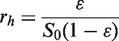
The well-known Kozeny–Carman equation for the specific permeability factor B, following the hydraulic radius theory, is
12
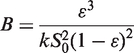

Accordingly, replacing B in Equation (6) by Equation (10) gives
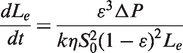
This equation will be the starting point for deriving a model for the capillary flow of liquid water through yarns. For horizontal flow of liquid water through yarn, and where no external pressure is forcing the liquid through, the pressure driving the liquid is primarily capillary pressure P. Therefore, the pressure differential

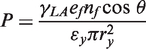
Extending to the arrangement of parallel fibers within yarn cross-section (Figure 2) and defining the pressure in terms of force per unit area, capillary pressure P can be described as
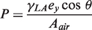
The total wetted perimeter of yarn cross-section in contact with liquid can be calculated as follows:
Schematic illustration of liquid moving in yarn.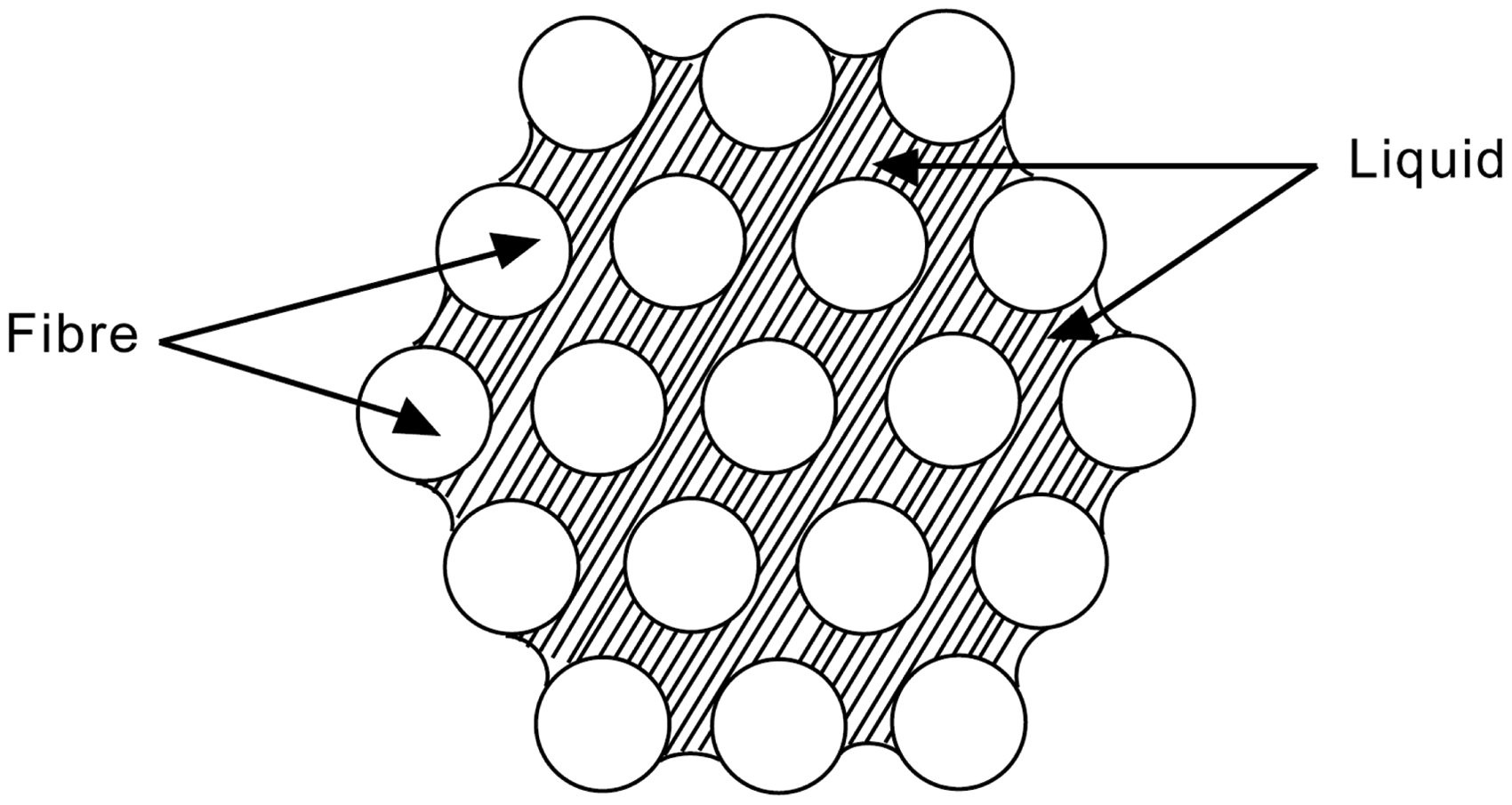

The area of the open space within the yarn cross-section can be calculated as follows:
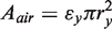
The equation for capillary pressure, Equation (14), then reads as follows:
Another quantity that needs to be redefined in Equation (12) is the hydraulic radius rh. Considering the definition for the hydraulic radius presented earlier, and extending to the arrangement of parallel fibers within yarn, it can be described as follows:

By replacing Equations (17) and (18) in Equation (12) we get the capillary flow rate through the yarn equation as follows:

Integrating, taking into account the boundary condition that Le = 0 when t = 0, leads to
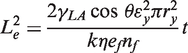
When the cross-section of fibers is considered to be circular, Equation (20) becomes
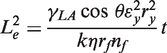
where rf is fiber radius.
The contact angle θ is the angle a drop of liquid forms when resting on a solid surface (Figure 3). There is an established relation between wettability of a surface and contact angle. Wettability of a surface by a liquid is known to be a result of the work of adhesion between the liquid and solid Equilibrium state of a liquid drop on a solid surface (adapted from Schick
19
).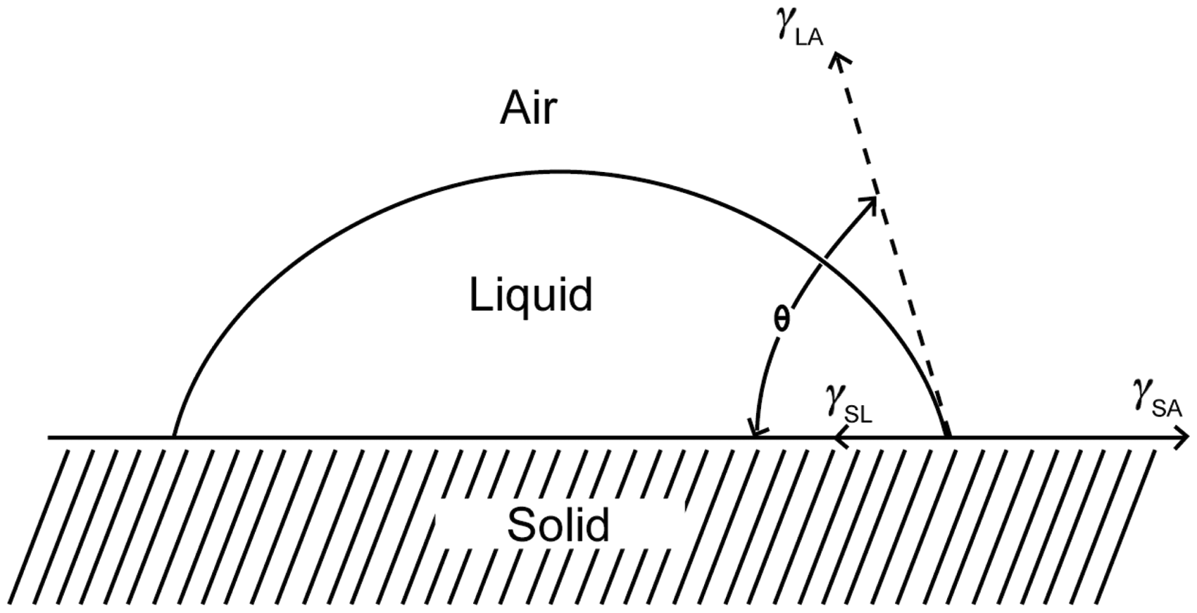

When the contact angle is 0°, the liquid will spread completely. The other extreme is when the contact angle is 180°, in which case the liquid forms a sphere on the solid surface. However, in most real situations the influence of gravity will distort the liquid so that an actual 180° angle would not be realistic.4,19,20 According to Equation (22), contact angle θ is a result of surface attraction forces, which are primarily dependent on the chemical make up of both the solid and the liquid. However, the early investigations by Adam, 4 Cassie 21 and Cassie and Baxter22,23 have demonstrated that the contact angle is also influenced by the geometric characteristics of the surface. They made the distinction between the real contact angle and the apparent contact angle. The real contact angle is dependent on the chemical nature of the constituent material of the solid surface. On the other hand, the apparent contact angle is dependent on the fine geometry of the structure as well as the constituent material chemistry. According to their experimental and theoretical analysis, for heterogeneous fibrous surfaces like yarns in contact with a given liquid, constituent aligned fibers and air space in between interact with the liquid. Therefore, constituent fibers and their arrangement within a yarn will determine the resultant contact angle. It is therefore the apparent contact angle measured on yarn that would best represent θ in Equation (20).
The shape factor constant k0 was given different values by Carman 12 depending upon the shape of the porous channels. Empirical values for various non-circular shapes were reported varying between 1.2 and up to 3. Carman found experimentally that the value of k = 5 and therefore suggests that a k0 value of 2.5 for a wide spectrum of beds of particles of non-circular cross-sections to be acceptable. Sullivan 24 and Sullivan and Hertel 25 have verified the value of k0 for flow of air through compact bundles of parallel textile fibers. They found that when the direction of flow was parallel to the axes of the fibers the k0 value was 2.5 and was constant for a range of porosities up to 0.88. This experimentally observed value will be used for the present work in calculating the capillary-driven liquid flow described in Equation (20).
As will be explained in the experimental section to follow, yarns will be drawn from plain knitted fabrics in order to account for production and fabric structure deformations on measured yarn parameters. Therefore, tortuosity of the liquid path through yarns in this work will be considered as that of the knitted loop. According to Equation (11), and as shown in Figure 4, the tortuosity factor for the knitted loop is calculated as the ratio of the effective length of the liquid path (Le), equivalent to half the stitch length, to the length of the test piece (Lt), equivalent to the course spacing.
Tortuosity of the plain knitted loop.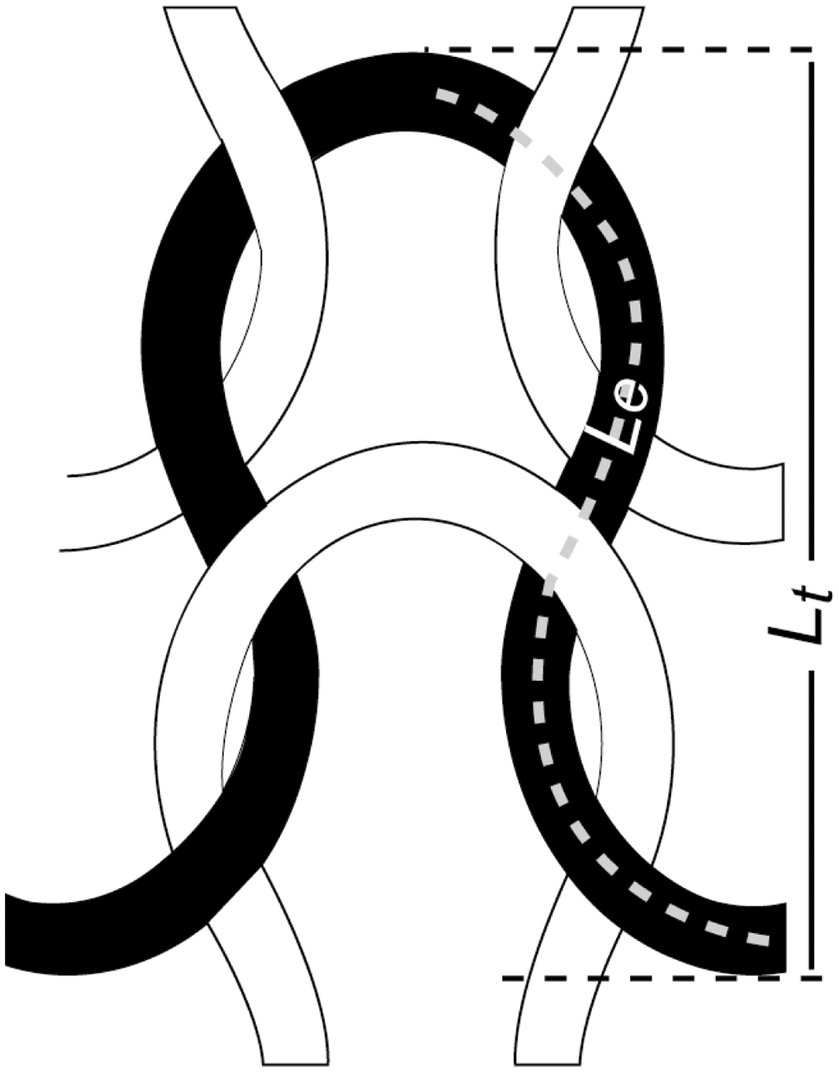
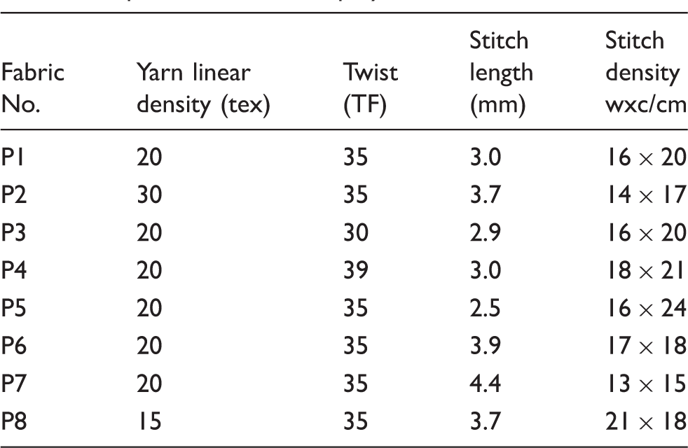
Experimental details
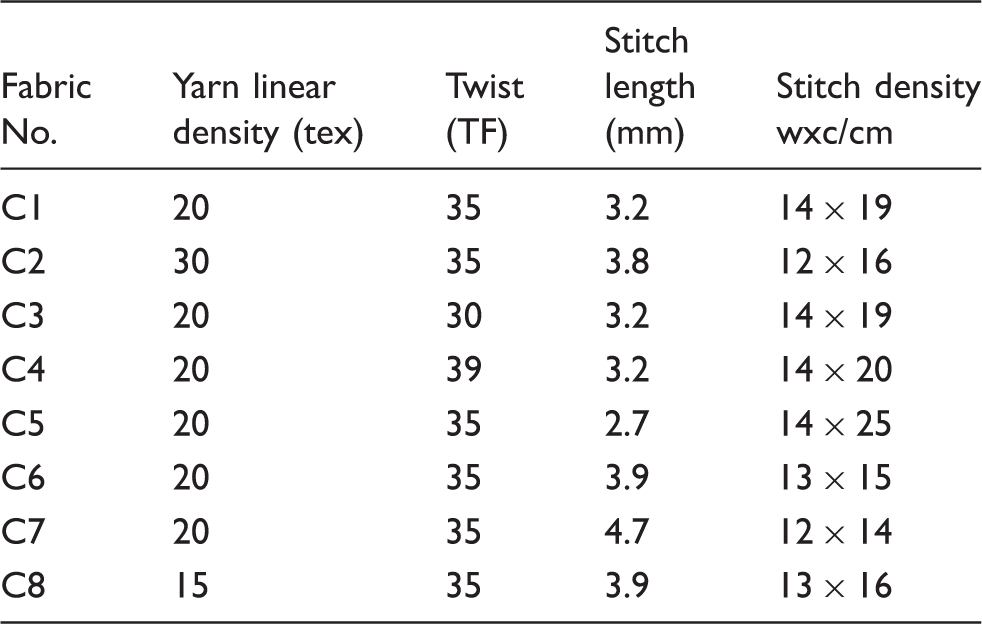
Specifications of the cotton fabrics
Specifications of the polyester fabrics
Specifications of the cotton/polyester blended fabrics
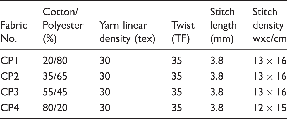
The yarns were taken from the produced knitted fabrics after washing and conditioning. Each yarn was mounted horizontally along a scaled ruler with a precision of 1 mm (Figure 5). Care was taken not to expose the yarn to any tension by mounting a 10 cm long yarn at 8 cm distance. A drop of 0.05% solution of blue dye was placed on one end of the yarn using a micrometer syringe and the drop volume (=8.2 mm3) was kept consistent with reasonable precision. The position of the wetted yarn length was recorded after 60 seconds. It was noted through preliminary tests that the flow slowed down substantially after this time. In some cases almost no further movement of liquid can be observed when the test time was extended for another 60 seconds. The average of 20 yarn flow readings was reported for each fabric sample following these outlined testing procedures.
Liquid flow through yarn test configuration.
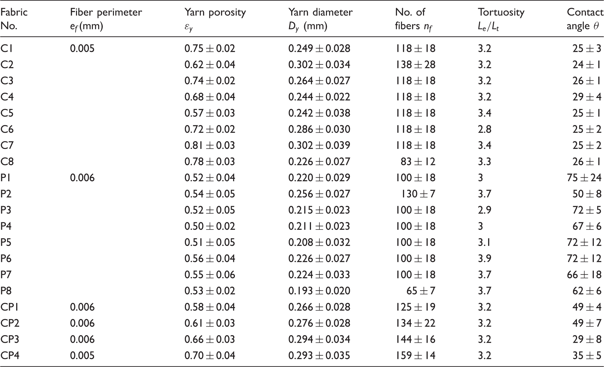
Measurement of yarn structural parameters is another important part of the experimental work. These include the fractional area open to flow equivalent to yarn porosity ( Steps of image processing and analysis in Image-J: (a) photomicrograph of a yarn cross-section; (b) binary image separated the foreground objects (fibers) from the background (Araldite resin); (c), (d) yarn perimeter defined by an ellipse fit; (e) image outline created and automatic measurement of yarn porosity, fiber perimeter and number of fibers within the yarn cross-section. Directly measured yarn parameters for calculating capillary flow of liquid water
Results and discussion
Results of horizontal capillary flow of liquid water through the yarns are reported as the distance liquid traveled across yarn length in mm after 60 seconds (Figure 7). Capillary-driven flow of water through each of the yarns was also calculated using Equation (20). Correlation between the calculated values obtained through the yarn model and the experimental results obtained through testing show high R2 value (Figure 8). This indicates the functionality of the model for predicting the capillary flow of liquid through yarns in terms of fiber and yarn structure parameters. The results obtained through the model are somewhat overestimated compared with the experimentally obtained results, which can be related to the approximation made to the yarn thickness based on an average diameter value. Nevertheless, the experimental and theoretical values are of the same ranking order. In light of the model validity, experimental results of capillary flow presented in Figure 7 can be further explained.
Experimental results of liquid water flow through yarns. Correlation between the experimental and theoretical results of liquid flow through yarns.

Firstly, the contact angle range associated with capillary flow of liquid represented in Equation 20 is between 0° and 90°, which corresponds with cos values between 1 and 0. Therefore, contact angle variation is expected to give a high magnitude of effect on capillary flow of liquid water through yarns when fibers of contrasting chemical and physical natures are used. Further analysis of the measured yarn parameters listed in Table 4 shows that cotton and cotton-rich yarns gave much lower contact angles than those obtained for the polyester yarns. The lower surface tension of the cotton fiber, and the more open fiber spacing within cotton yarns indicated by higher porosities, in contrast with the polyester fiber and yarns, are both factors that resulted in the lower contact angles observed. This is in agreement with the earlier observations and theoretical analysis presented by Cassie and Baxter 22 on the effects of constituent material and surface geometry on the contact angle. The wide range of variation of this parameter resulted in the significantly lower capillary flow rates obtained for the polyester yarns P1–P9 and the yarns with higher polyester ratio in the blend with cotton, Cp1 and Cp2.
Secondly, according to Equation (20), the flow rate is expected to increase as the ratio of interfiber pores total area, which is a function of yarn porosity and diameter squared
Finally, based on the strong relation between capillary-driven liquid flow and the ratio of interfiber pore area to the total fiber perimeter within the yarn cross-section, further deductions can be made on optimum yarn structural parameters for efficient liquid transfer performance. The relation implies that for a particular yarn linear density made of a given fiber, yarns made of fibers having non-circular cross-sectional shape would result in a decrease in liquid velocity compared to yarns made of fibers having circular cross-sectional shape. This is due to the increase in total fiber perimeter within the yarn cross-section when a fiber of non-circular cross-section is used. Similarly, according to Equation (21), when fibers of circular cross-sections are considered, decreasing fiber thickness would result in a decrease in liquid velocity too. This is due to the increase in total fiber perimeter within the yarn cross-section as a result of the higher number of fibers used. However, in practice altering fiber cross-sectional shape or thickness would alter yarn packing, and subsequently its porosity and diameter, which directly affects the area of interfiber pores. It is this factor that will have the higher impact on the velocity, as the results and analysis showed. Various researchers presented experimental investigations of the effects fiber diameter and yarn cross-sectional shape have on capillary flow of liquid water through yarns and fabrics.30–32 However, micro-structural analysis of the produced yarns was not carried out nor were any correlations with established theoretical models. Therefore, the effects fiber parameters have on tested yarns diameters and porosities, and therefore on the flow, were not clearly understood. The model presented in this paper would therefore provide theoretical basis, which would inform the engineering of yarns with predetermined liquid water transfer properties.
Conclusions
A mathematical model for capillary-driven liquid water flow through yarns was presented. Darcy’s law describing flow through porous media 17 and the well-known Kozeny–Carman equation for the specific permeability factor following the hydraulic radius theory 12 form the basis for the presented equation. The validity of the model was confirmed by comparing calculated results against experimental results of liquid water flow through real yarns. The effects of various yarn and fiber parameters on capillary flow in yarns were explained. The model predicts the high magnitude of effect contact angle has on capillary-driven flow rate in yarns. This was evident from the experimental results of the high flow rates obtained for the cotton and cotton-rich yarns contrary to the polyester yarns, which showed much slower flow rates. Also, the model predicts that as the ratio of interfiber pore space area to the total fiber perimeter within yarn increases the flow rate is expected to increase. Interfiber pore space is a function of yarn porosity and diameter squared, while total fiber perimeter is a function of fiber perimeter and number of fibers within the yarn cross-section. Being a squared term in the model, variation of the area open to the flow within the yarn has a strong effect on capillary-driven liquid flow. Experimental results confirmed this trend.
The deductions from the model are contrary to some of the generalizations often made about the fabrics produced from yarns made of non-circular cross-sectional shaped fibers or microfibers as fast wicking. The common understanding is that the fiber geometry in these yarns results in higher fiber surface area and a higher number of smaller capillaries, thus increasing capillary force. However, as shown from Equations (17) and (20), the magnitude of the capillary force and liquid velocity show opposite trends with respect to the ratio of interfiber pore space to the total fiber perimeter within the yarn cross-section. This is in agreement with the model presented by Rajagopalan et al., 13 which speculated that for a filament bundle, increasing the void area while maintaining constant perimeter decreases the final height liquid reaches within the bundle, but increases the initial rate of penetration. On that basis, it is speculated that at constant yarn linear density, yarn made of fiber, which has non-circular cross-sectional shape or lower thickness, would result in faster capillary flow, only if the fiber parameters selected resulted in a more open yarn packing.
The conceptions of the better performance of fabrics made from synthetic microfibers or fibers with non-circular cross-sections can be related to other aspects, which affect the human perception of comfort. The innovative structural modifications that are usually incorporated with such newly developed functional fabrics have a role to play toward that perception. It must also be noted that such fibers are usually produced into filament fibers, which give a smooth yarn surface as opposed to a hairy yarn surface made from conventional staple fibers. Not only would this affect sensorial comfort but it could also have an effect on the flow rate of the liquid due to the continuity of pores. This factor needs further investigation. Also, due to the critical role yarn porosity plays in the flow rate, further research is needed in order to draw relations between yarn porosity and fiber dimensions, morphologies and yarn production methods. Finally, since the assembly of yarns into a fabric structure dictates the liquid paths through interfiber and interyarn pores, extending the presented model to study flow through knitted fabrics will be a subject of future research.
Footnotes
Funding
This research received no specific grant from any funding agency in the public, commercial or not-for-profit sectors.