
Abstract
In order to optimize the color-changing effects of textile knife-coatings containing multi-layered mica pigments (effect pigments; EPs), the properties and structure of the coating formulation/layer during and after application were investigated. Three pigment coating formulations were prepared by first mixing the EP dispersion into a water-based polyurethane binder. Different types of rheology modifiers (RMs), liquid dispersion of sodium polyacrylates (LDPSAP), hydrophobically alkali swellable emulsions (HASEs) and hydrophobically modified ethoxylated polyurethane, were then added to the dispersion. The rheological behavior of the coating formulations was characterized in terms of the shear rate dependence of the viscosity. The formulations were applied onto the same type of textile substrate using a knife-coating technique. The choice of RM as well as variations in gap height and coating speed increased the solids deposit. The increased amount of coating deposits (thicker coating layers) corresponded to more and better dispersed EPs within the coated layer as well as more horizontally oriented platelets as confirmed by scanning electron microscopy. Multi-angle spectrophotometer measurements showed that the CIE L*a*b* color coordinates varied strongly depending on detection angle. The variations of the absolute values of L* and a* were more pronounced between –15° and 15° detection angles, corresponding to angles with the greatest visual color changes. The slowly coated samples with higher solids deposit were measured to be lighter and of higher chroma compared to samples coated at a higher speed. Generally, the color-changing effects were governed by the choice of RM and coating parameters in terms of variations of the amount of coating deposited onto the samples.
Keywords
Textiles with new or improved eye-catching and optical functions are constantly under development and are a hot topic among researchers and designers.1–7 Multi-layered mica pigments8,9 are a type of effect pigment (EP) that provide angle-dependent optical effects in the form of color changes (flip-flop or color travelling effects). These types of EPs have a promising future for functional purposes, aesthetic eye-catching applications and product authentication.
For optimal performance, the EP platelets should be aligned parallel to the surface of a flat substrate. Within the automotive and paper industries, 10 published papers and commercial reports therefore tend to focus on the application of EPs on flat substrates. Few publications deal with the application of EPs on textile fabrics. Weitzel 11 presented the use of EPs in the printing ink industry, briefly describing the screen printing method for textile application. However, recent work 5 has shown that small amounts of EPs as a filler in a water-based polyurethane (PU) binder can successfully be applied on textiles using a knife-coating method, providing them with angle-dependent color changes. The color changes were less pronounced on the rougher textile surfaces than on smooth paper test charts. This was suggested to correlate with the less horizontal orientation of EP platelets in the coatings of woven fabrics. Although the color-changing effect decreased with increased fabric surface roughness, the changes were detected on both black and white substrates, both visually and instrumentally, in the latter case using a multi-angle spectrophotometer with five detection angles. However, the results also confirmed that a spectrophotometer with more detection angles is needed for characterizing the strong color changes, visually observed. Therefore, a spectrophotometer with six (including −15°) detection angles is used in the experimental part in this study.
When using knife-coating,12,13 the amount of coating deposited onto the fabric can partly be controlled by adjusting the gap between the knife and fabric. Other parameters considered to influence the coating deposit are the solids content, the viscosity and the surface tension of the coating formulation,13–15 as well as the coating speed and the fabric structure.16,17 To the authors’ knowledge, for knife-coatings, no existing models are fully suitable to predict the coating deposit on textile substrates. Existing models address penetration depths of coating formulations into the textile structure16,17 or coated film thickness added to a substrate,18,19 the latter neglecting the nature of the porous textile structure. Since the amount of coating may have a major impact on the color-changing properties, this study will evaluate the parameters influencing the measured coating deposit.
To prepare a uniformly dispersed pigmented coating formulation, pre-wetted pigments are required,5,11 which dilute the system and decrease its viscosity. For EP formulations, the viscosity should be high enough at low shear rates to prevent pigment sedimentation during storage 10 and low enough during the application process to promote flow and leveling. Therefore, it is crucial to adjust the viscosity with a rheology modifier (RM) to suit the specific application method and fabric.15,20 Further, Mail et al. 21 studied liquid paints containing EP; the distribution and orientation of platelet-shaped pigments within the dried coated layer were found to be highly influenced by the formulation ingredients and/or the process parameters. It is quite clear that further studies on how the coating formulations and coating parameters may influence the distribution and orientation of EPs and thus their performance in textile coatings are required.
RMs can provide water-based formulations with a thickening effect associated with different mechanisms. Liquid dispersion polymers (LDPs) containing acrylic polymers are widely used as a RM for waterborne coatings within the textile printing industry. 22 In the case of LDPs containing, for example, anionic sodium polyacrylate, the binding of water (hydration) around the anionic carboxylic groups in the main chain makes the polymer particle swell. As such, it takes up a larger volume and leaves less free space for other ingredients in the formulation (binder polymers and pigments) to move freely; consequently, the viscosity increases. 23 A possible drawback with a thickener only acting in the water phase is its inability to improve the compatibility between different components, such as pigments and polymer dispersion particles. 24
There are essentially two types of associative thickeners, hydrophobically modified ethoxylated polyurethanes (HEURs) and hydrophobically modified alkali swellable emulsions (HASEs).22,24,25 Both types may interact with the polymers and the pigments when added to a formulation,24,26 thus possibly contributing to a homogeneous distribution of the EPs. HEURs are linear triblocks, generally composed of a main chain containing urethane and ethylene oxide (EO) groups with terminal hydrophobic groups. The EO groups give a hydrophilic character interacting with the surrounding water, whereas the hydrophobic groups are repelled by water and forced to self-assemble, forming flower-like micelles. At a certain concentration, the chain ends may bridge the different micelles, creating a strong three-dimensional network.24,27 The interaction between the PU-containing dispersion, that is, the binder, and HEUR has also been explained 28 to be due to the ionic adsorption of the protonated EO group and the ionic groups on the surface of the PU-particle, as well as hydrogen bonds between the urethane groups of the PU-dispersion and thickener. The thickening effect of HEUR is based on this associative network, which is said to have a higher mobility in dilute solutions compared to the HASE type.
HASE is described as having a comb-like structure, with acid-based polymers in the main chain onto which organic surfactants have been grafted.24,27 The surfactant can be poly(ethylene glycol) chains with a terminal hydrophobic group. The thickening behavior of this RM depends strongly on the pH of the coating formulation, and the main chain polymer only becomes soluble when placed in an alkaline medium. The polymer chains become stretched due to the electrostatic repulsion of the charged groups and the RM swells with the amount of adsorbed water. Like HEUR, HASE has the ability to form self-associative and three-dimensional networks by forming micelles. However, HASE binds water via the polyelectrolytic main chain, limiting the mobility of the comb-structure in water; this may be why HASE offers the best performance against phase separation compared to HEUR. The HEUR and HASE types may also associate with the polymers and the pigments when added to a formulation, promoting a uniform and stable formulation of both pigments and dispersion particles,24,26 possibly also contributing to a more homogeneous color appearance. The influence of RMs on water-borne polymer dispersions for paints and textiles has been discussed by others.29–35 However, the influence of adding RMs with different thickening mechanisms in a water-based PU formulation containing platelet-shaped EPs needs further attention.
The aim of this experimental study is to assess how different coating formulations and coating parameters influence the color-changing effects of textile knife-coatings containing EP. Different types of RMs (LDPSAP, HEUR and HASE) were included in order to investigate their performance and influence on the viscosity. By varying the coating gap height as well as the coating speed, the behavior of the coating formulations during and after application was studied. The influence of the RMs and coating parameters on the distribution and orientation of EP platelets within the coated layer is also investigated.
Experimental details
Materials
Fabric
A black plain woven fabric made from poly(ethylene terephthalate) (PET) continuous multifilament yarns, scoured and heat-set by the supplier (Almedahl-Kinna AB, Sweden), was used as substrate. The fabric had a thread count in warp and weft of 30.5/24 and a mass per unit area of 110 g/m2. It was selected for its smoother surface, resulting in a more pronounced in-plane orientation of pigment platelets compared with fabrics having rougher surfaces. 5
Coating ingredients
The commercial binder (Performax 16297G, Diazo AB, Sweden) is an aqueous dispersion containing thermoplastic aliphatic polyester-PU and hydroxyethyl cellulose (HEC) as a thickener/stabilizer to avoid flocculation of the binder particles. The EP is a multi-layered mica pigment (Colorstream T10-05 Pacific Lagoon, kindly supplied by Merck AB, Sweden) having the following structure: a mica platelet coated with a layer of titanium dioxide, followed by a layer of silicon dioxide and finally a layer of tin oxide. The platelet diameter distribution was 10–60 µm with a mean particle size of 24 µm and a thickness below 1 µm, according to the supplier. The EP is categorized as an interference pigment with a multicolor effect within the turquoise-blue-violet range, depending on the observation angle. One of the RMs used was Rheosol PTP (Diazo AB, Sweden). It is a liquid dispersion of anionic sodium polyacrylate (LDPSAP), widely used as a thickener for waterborne coatings within the textile printing industry since it provides cost-effectiveness and adjustable shear viscosities, according to the supplier. Two types of associative thickeners were used, HEUR and HASE. The HEUR type was Borchi Gel L75N (from OMG Borchers GmbH/IMCD Sweden AB), a non-ionic liquid thickener. The HASE type was Acrysol TT-615 (from Dow Chemical Company, kindly supplied by IMCD Sweden AB), an anionic thickener. A more detailed description of the RMs can be found in the first section.
Sample preparation
Coating formulations, composition in weight%
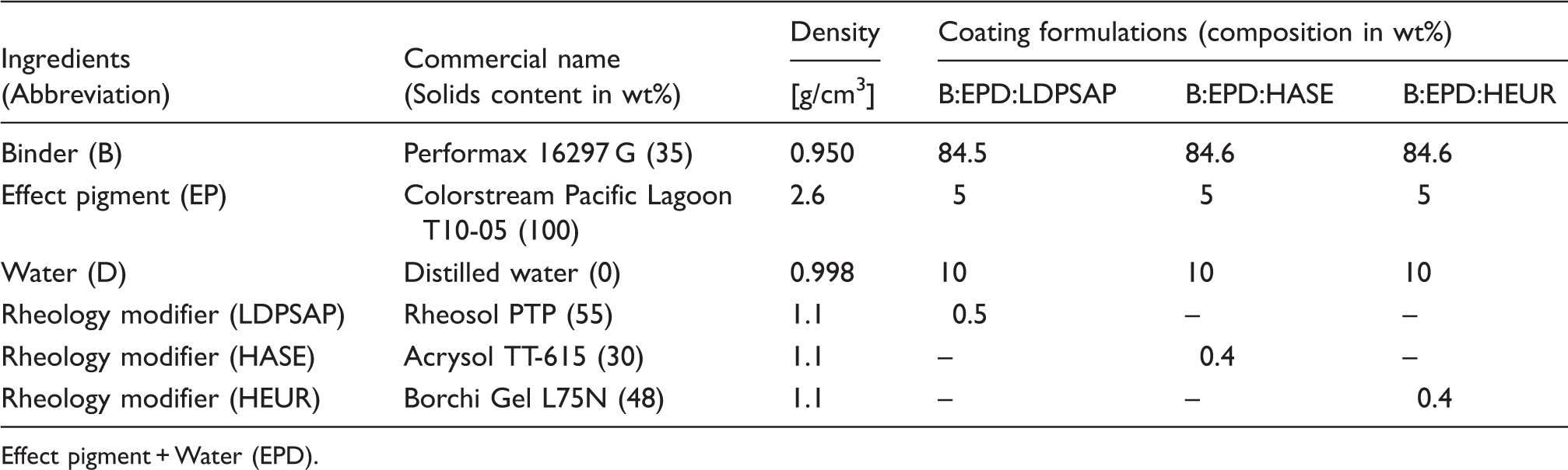
Effect pigment + Water (EPD).
Coating parameters
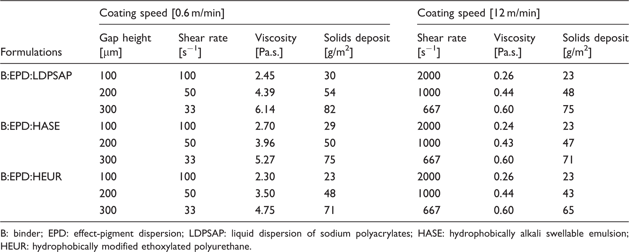
By using the theoretical solids content for each ingredient given in Table 1, the coating pastes were calculated to contain approximately 35 weight% solids. This is in agreement with the solids content obtained by differentially weighing each coating paste before and after drying for 10 minutes at 100℃. By using the density of each ingredient and composition in weight% for each coating formulation, all coating formulations were calculated to have a density of 1.038 g/cm3.
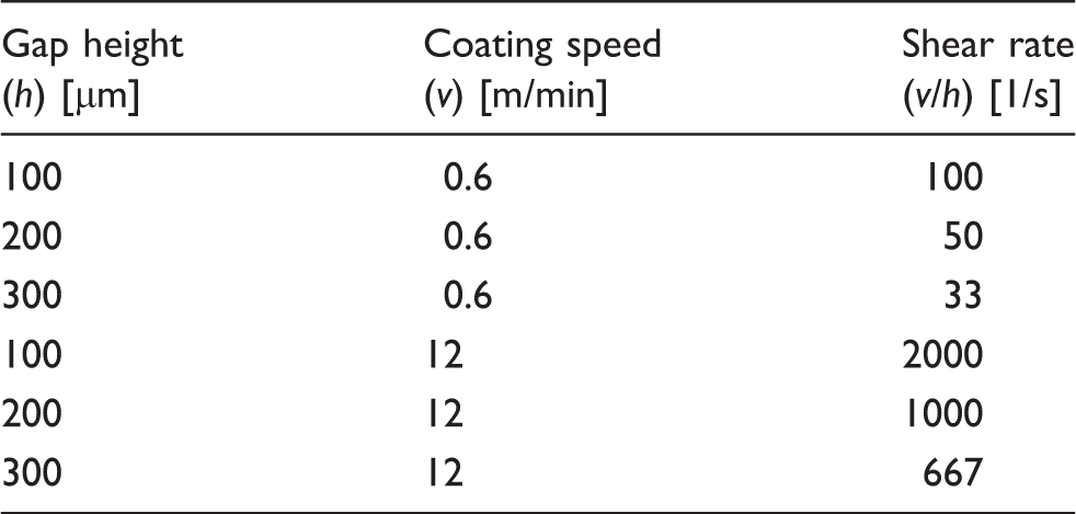
The three different coating formulations were applied to the substrate in the warp direction of the woven fabric with a lab-scale knife-over-table coating method. Fabric samples of 20 cm × 50 cm were taped to an even surface and the coating formulation was manually applied using a film-applicator (ZUA 2000, Zehntner) with a width of 15 cm and gap settings of 100, 200 and 300 µm, as shown in Figure 1. To minimize any pressure variation on the fabric from the rolling bank, 50 cm3 of each formulation was evenly distributed in front of the knife. Two different coating speeds were used, 0.6 and 12 m/min, generating different shear rates depending on gap height, as shown in Table 2. The coated samples were first dried on stenter frames for 10, 15 and 20 minutes at 100℃, adjusted on the gap setting, and then thermofixed for five minutes at 150℃ in a low convection heat oven (D-36-03-EcoCell, Rycobel NV). Two replicas of each sample (3 × 2 × 3 × 2 samples) were produced, resulting in a total of 36 samples.
Lab-scale knife-over-table coating method.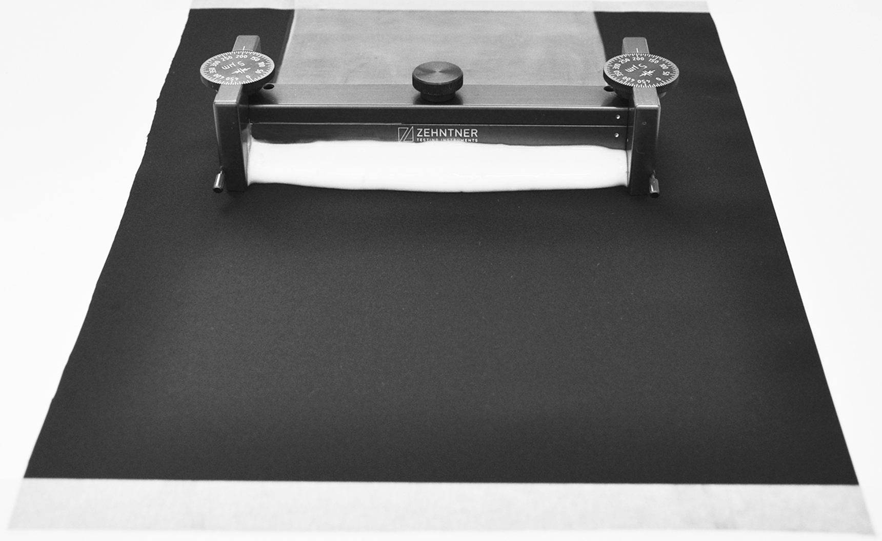
Characterization
Viscosity measurements
The shear viscosities (η) of the coating formulations were measured at 23℃ using a Paar Physica MCR 500 rheometer with a cone-and-plate setup. To simulate the process conditions during the coating procedure, the measurements were done at shear rates between 1 and 2000 s–1 starting from low to high and then back to low again. For each coating formulation, three measurements were made.
Solids deposit
Within this study, the solids deposit is defined as the amount of solids added to the substrate and was determined by differentially weighing the fabric before and after the coating and drying procedures.
Surface tension
The surface tension (γ) was measured at 25℃ with a Sigma 70 tensiometer (KSV) using the DuNoüy ring method. For each formulation, three measurements were made.
Surface structure and pigment orientation characterization
Scanning electron microscopy (SEM) images were obtained using a JEOL JSM-6610LV. The microscope was equipped with an energy-dispersive X-ray spectrometer (EDS) for elemental analysis. Secondary electron images were analyzed with regard to the surface structure of samples and also backscattered electron images of cross-section samples were analyzed regarding the EP distribution and orientation within the coating layer. Samples of 5 mm × 5 mm (including the cross-sectional samples) were cut with a scalpel from the coated textile fabrics before they were attached to aluminum stubs. The samples were then examined at magnifications of 100× and 150× using an accelerating voltage of 10 kV.
Angle-dependent color measurements
A multi-angle spectrophotometer (MA96 from X-Rite, USA) was used for the colorimetric analysis. Illumination was at a fixed angle of 45° relative to the normal and the instrument measures colors at six different detection angles: –15°, 15°, 25°, 45°, 75° and 110° relative to the specular angle, as shown in Figure 2. The data were evaluated with respect to the (CIE 1964) 10° standard observer and with D65 (average daylight) as the standard illuminant. The illumination source and the detector were consistently placed along the weft direction of the samples. Measurements were made on duplicate samples at 10 different positions on each sample, and mean values and standard deviations for each sample were calculated. The color of samples was characterized using the CIE L*a*b*-coordinates, represented two-dimensionally as described elsewhere.
5
Graph displaying the angles used by the spectrophotometer for illumination and measurement. All angles are given relative to the specular angle.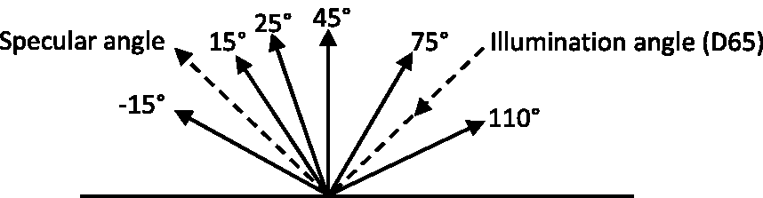
Results and discussion
Influence of rheology modifiers on the shear viscosity of coating pastes
In Figure 3, the viscosity versus shear rate is plotted logarithmically for all coating formulations described in Table 1, showing a pseudoplastic (shear-thinning) behavior typical of non-Newtonian fluids. The applied flow field induces alignment and disentanglement of the polymer molecules (in the coating formulations) in the flow direction, making them slip past each other more easily with increasing shear rates.
36
The viscosity decreased at all used shear rates by adding the effect-pigment dispersion (EPD) to the binder (B) stabilized with HEC. HEC is only active in the water phase where it creates a network of entangled hydrated chains. The strength of this network depends on the number of entanglements in the water phase and since the concentration of HEC decreased in the B:EPD formulation the viscosity also decreased. The B:EPD system had a tendency for a more rapid phase separation during storage (lower shear rate) compared to formulations containing RMs, visually observed after three days’ storage.
The viscosity versus shear rate for plain binder(B), binder mixed with effect-pigment dispersion (B:EPD) and coating formulations containing different types of rheology modifiers, B:EPD:LDPSAP; B:EPD:HASE and B:EPD:HEUR. Error bars represents standard deviations. EPD: effect-pigment dispersion; LDPSAP: liquid dispersion of sodium polyacrylates; HASE: hydrophobically alkali swellable emulsion; HEUR: hydrophobically modified ethoxylated polyurethane.
Adding small amounts of RMs (LDPSAP, HASE or HEUR) resulted in an increased viscosity over the measured shear rate range, enough to delay phase separation during storage. B:EPD:LDPSAP had the highest viscosity at lower shear rates. This formulation also had a steeper slope showing a somewhat more pronounced shear thinning behavior compared to HEUR and HASE having more similar viscosity curves, a result that can be correlated to their different thickening mechanism. LDPSAP polymers, which swell due to hydration (including the other polymer particles in the formulation), more easily align themselves with the shearing forces, whereas the hydrophobic associative networks created by HEUR and HASE resist the deformation forces better, resulting in a less pronounced shear thinning behavior.
B:EPD:HASE, compared to B:EPD:HEUR, provided only slightly higher viscosity values up to shear rates of 500 s–1, and at higher shear rates, the curves intersected each other. B:EPD:HASE was also slightly less shear-thinning up to shear rates of 500 s–1 compared to B:EPD:HEUR, as seen in Figure 3. This may be correlated to the fact that HASE (unlike HEUR) binds water to its polyelectrolytic main chain and thereby limits the mobility of the associate network in the formulation, whereas the HEUR network has a higher mobility in the water phase and provides less resistance to flow.
Influence of coating parameters on solids deposit
Solids deposit obtained with the different coating formulations, gap heights and coating speeds, experimental and calculated values
B: binder; EPD: effect-pigment dispersion; LDPSAP: liquid dispersion of sodium polyacrylates; HASE: hydrophobically alkali swellable emulsion; HEUR: hydrophobically modified ethoxylated polyurethane.
From Table 3, it is evident that, with exception of B:EPD:HEUR coated with a gap of 100 µm, a higher coating speed resulted in lower solids deposit, up to 23%. This difference in solids deposit was more pronounced at the smaller gap heights.
A trend of increasing solids deposit in the order of LDPSAP > HASE > HEUR, (except for samples coated with a gap height of 100 µm at the higher coating speed) can be noted from Table 3. Thus, there was an influence of the chosen RM on the solids deposit, which at least at the lower coating speed followed the viscosity differences between the formulations, that is, a higher viscosity was associated with a higher solids deposit. At the higher coating speed, the corresponding viscosity differences were only marginal. The reason for obtaining a higher solids deposit at a lower coating speed (at constant gap height) may be speculated on. At lower coating speeds (or lower shear rates), the viscosity is clearly higher, which could give rise to a higher hydrodynamically induced force under the knife. This force compresses the flexible substrate, allowing a thicker wet film to pass under the knife and hence giving rise to a higher solids deposit. 37 It should be mentioned that the formulations showed no significant variations in density or surface tension, 1.04 g/m3 and between 41 and 42 mN/m, respectively, and are not considered to influence the solids deposit variations.
Influence of coating parameters on the surface structure and pigment orientation
The top-view and cross-section SEM images in Figure 4 are B:EPD:HASE samples coated at the higher speed (12 m/min). These were selected to represent the influence of gap heights on the surface appearance and the orientation of the pigment platelets. The type of thickener, coating speed and, consequently, the viscosity in general did not seem to influence the distribution or the orientation of the platelets. As seen in Figures 4(a)–(c), there was a clear improvement of the surface smoothness with increased gap height due to increased solids deposit and coating thickness. The higher solids deposit filled out the valleys between the yarns and leveled out surface irregularities from the woven structure and the multifilament yarn.
Scanning electron images, top-views (a)–(c) and backscattered images of cross-sections (d)–(f) of B:EPD:HASE samples coated with a coating speed of 12 m/min. The fabrics were coated with increasing gap heights from top to bottom: 100, 200 and 300 µm. B: binder; EPD: effect-pigment dispersion; HASE: hydrophobically alkali swellable emulsion.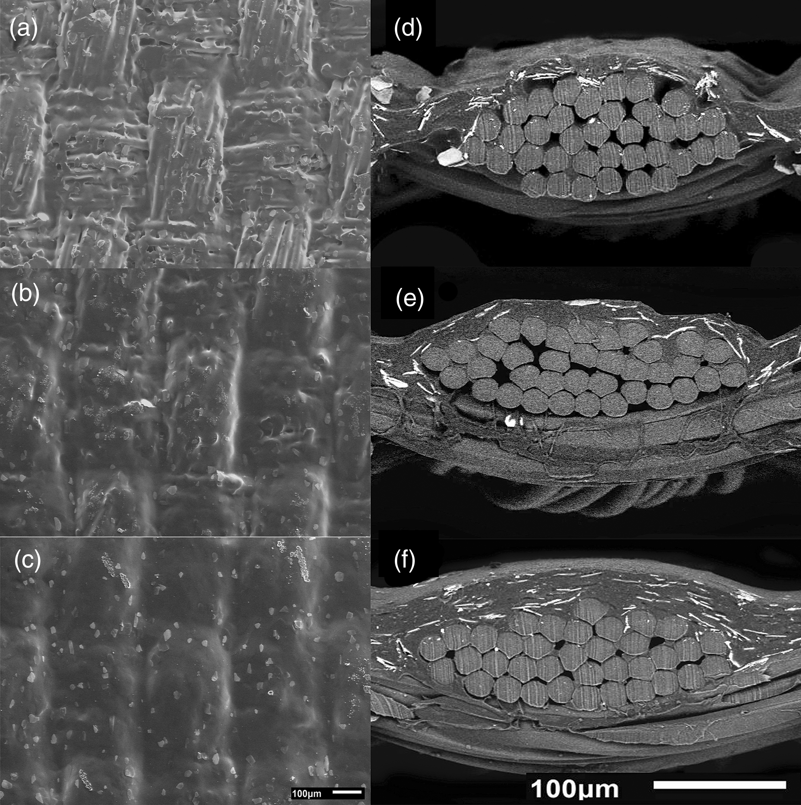
In the backscattered electron images (see Figures 4(d)–(f)), the EPs are contrasted against the binder, showing their distribution and orientation within the dried coated layer. The layers were roughly estimated to have thicknesses of 8, 19 and 29 µm (by cross-section SEM images) corresponding to approximately 10% of the gap heights of 100, 200 and 300 µm, respectively. Within the 8 µm thick layer, the EPs appeared to form compact stacks close to the filament surfaces. Some of these stacks bridged two or more filaments within the yarn, and may possibly prevent the binder from interlocking around the filaments, thus leading to a reduced adhesion between the coating and fabric. The platelets within the thinner layer were not perfectly horizontally oriented, which can be a consequence of the drying process. When the water in the suspension (formulation) evaporates and also is drained into the fabric structure, the polymers coalesce. Subsequently, shrinkage of the film (wet coating) 10 takes place and forces the platelets to orient themselves along the curved surfaces of the filaments.
Generally (and as expected), higher amounts of pigments were observed within the thicker coating layers (Figures 4(e) and (f)). The pigment platelets are also more homogeneously distributed within the layers, some were close to the filaments, but without bridging them as was seen in the thinner layer. Furthermore, some pigment platelets appeared to be located rather close to the surface of the coating layer. Despite the semitransparent nature of the pigments, obviously the thicker layers should promote better coverage of the substrate surface. The pigment distibution within the layer here is suggested to be the result from the forming of a layered structure under the knife during fabric coating. 22 Assuming that the layers consist of polymers and platelets (oriented into the shear direction) with a continuous liquid phase, when the shearing stops, the viscosity of the wet layer instantly increases. This may to some extent prevent the pigment platelets from compacting or sedimenting down to the bottom of the coating layer and instead stabilize them in the distributed way seen in Figure 4(f). It is not unreasonable that this cause of events could lead to a more homogeneous distribution of the platelets in the thickness direction in case of the thicker layers.
As already mentioned, it was hard to visually detect (in SEM images at microscopic level) any significant effects on the distribution or the orientation of the platelets by the viscosity or coating speed. However, the coating speed (i.e. the shear rate) at a constant gap height influenced the solids deposit, which should have an impact on the amount of pigments within the layers.
The influence of the coating speed on the surface structures of HASE samples coated at 0.6 and 12 m/min with the gap set to 100 µm is shown in Figure 5. It was quite obvious that the sample coated at the lower speed, Figure 5(a), exhibited a smoother surface due to an increased solids deposit of 6 g/m2 (Table 3) and probably a somewhat thicker coating layer when compared to the corresponding sample coated at 12 m/min (see Figures 5(c) and (d)). In those micrographs, the filaments and pigments are emphasized on the coated surface compared to the appearance exhibited in Figures 5(a) and (b). Since the difference in solids deposit between samples coated at different speeds decreased with increasing gap heights, it was difficult to distinguish differences in smoothness by SEM for these samples.
Scanning electron microscope images and backscattered electron images of hydrophobically alkali swellable emulsion (HASE) samples coated with a gap height of 100 µm using coating speeds of 0.6 m/min (a), (b) and 12 m/min (c), (d). The magnification was 100×.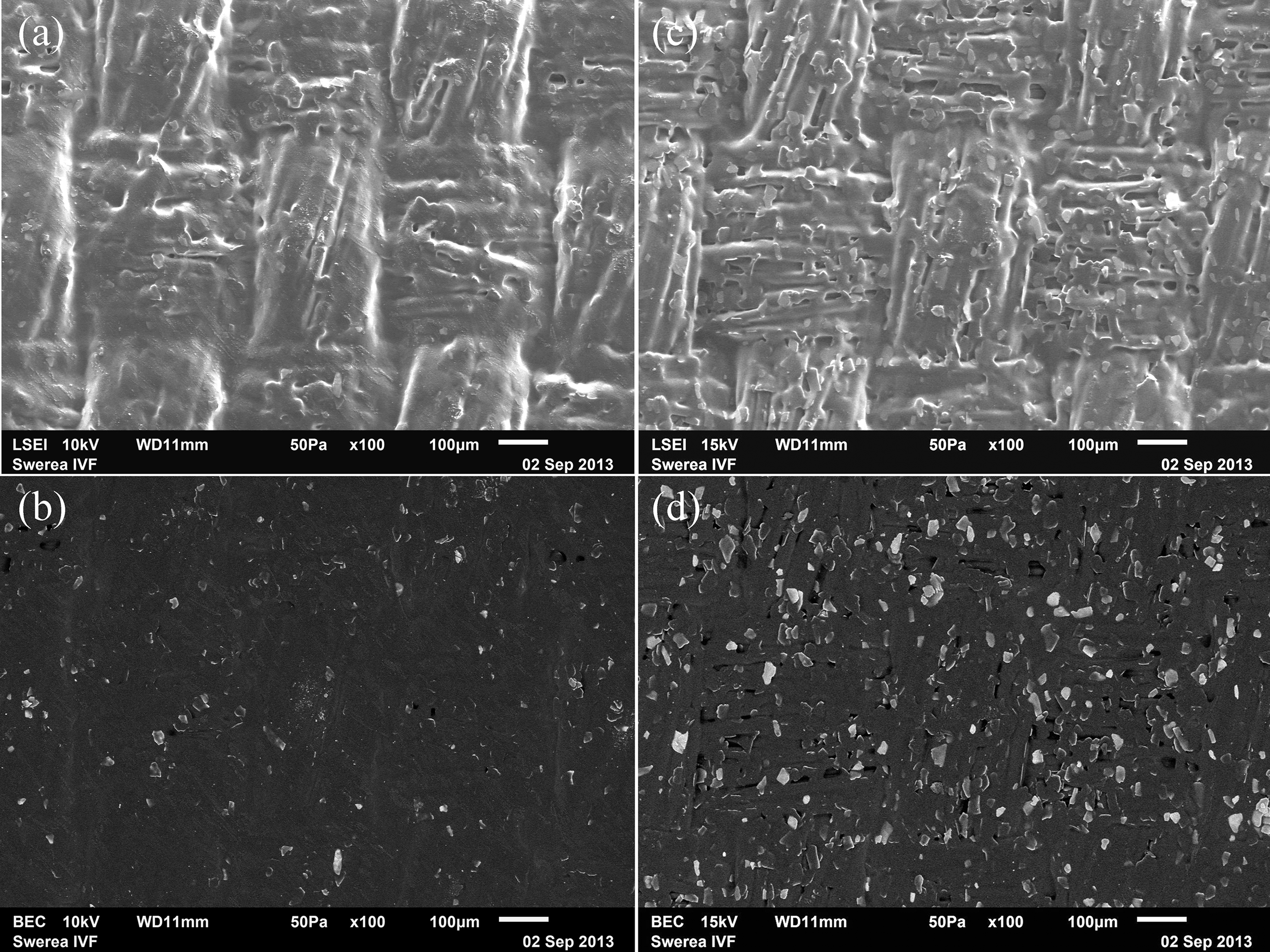
The EPs are distinguished as the lighter gray non-symmetrical spots on the coated surfaces seen in the backscattered electron images in Figures 5(b) and (d). In Figure 5(b), the pigment particles are not as clearly revealed in the sample coated at the lowest speed, possibly because they are better covered by binder polymer.
Preliminary studies indicated that the mechanical properties of the coated samples essentially were influenced by the coated layer thickness generated by gap height. As expected, the fabric stiffness was found to increase with increasing layer thickness. This is possibly because increased amount of solids deposit interlaces filaments and yarns, which restrict fabric flexibility. Preliminary studies also indicated that the abrasion resistance of coated samples was lower for the thinner coated samples. For these samples the weight loss after 5000 Martindale cycles was slightly higher in comparison to the thicker coated samples. Further, when comparing the color differences before and after abrasion, the color differences were also greater for the thinner coated samples. The adhesion between polymeric binder and substrates may therefore be lower for thinner coated samples, possibly due to poorer interlocking around the filament and also that the stacks of EPs formed near the filament surfaces (cf. Figure 4(d)) may in fact lead to reduced adhesion, as previously discussed. On the other hand, within the thicker coated layer with increased pigment distribution, the affinity between pigment and binder as well as binder and substrate are suggested to be greater. The thermodynamic process that most certainly influences the pigment distribution and orientation may have an impact on the adhesion and thus also on the mechanical properties of the coated samples, and should therefore be assessed in a follow-up study.
Influence of coating formulation and gap height on color differences
Lightness measurements
The influence of the different coating formulations and the gap heights on the lightness, L*-value, with increasing detection angles (relative to the specular angle) is shown in Figure 6 in the case of the samples coated at the lowest speed, 0.6 m/min. In general, the L*-value was highest at –15°, close to the specular angle 0°, and decreased with increasing angles. This decrease was more pronounced between −15° and 75°. At larger angles, the lightness was less dependent on detection angle, but varied slightly depending on the gap height. Note that the L*-values for the uncoated black fabric were much lower (darker) with only a small variation over the measured angle region. In more detail, however, even for this uncoated substrate, there was a minor decrease in lightness between −15° and 75° angles. Assuming that this decrease depended on the surface structure of the uncoated black fabric and that the structure was not completely hidden by the coating layer, it is plausible that the structure of the fabric to some extent influenced the angle-dependence of the lightness of the coated substrates.
CIE L*-values as a function of detection angle for effect pigment coated samples produced using a coating speed of 0.6 m/min, and for plain black substrates. The samples were produced using different gap heights and rheology modifiers (RMs). The bars denote the standard deviations.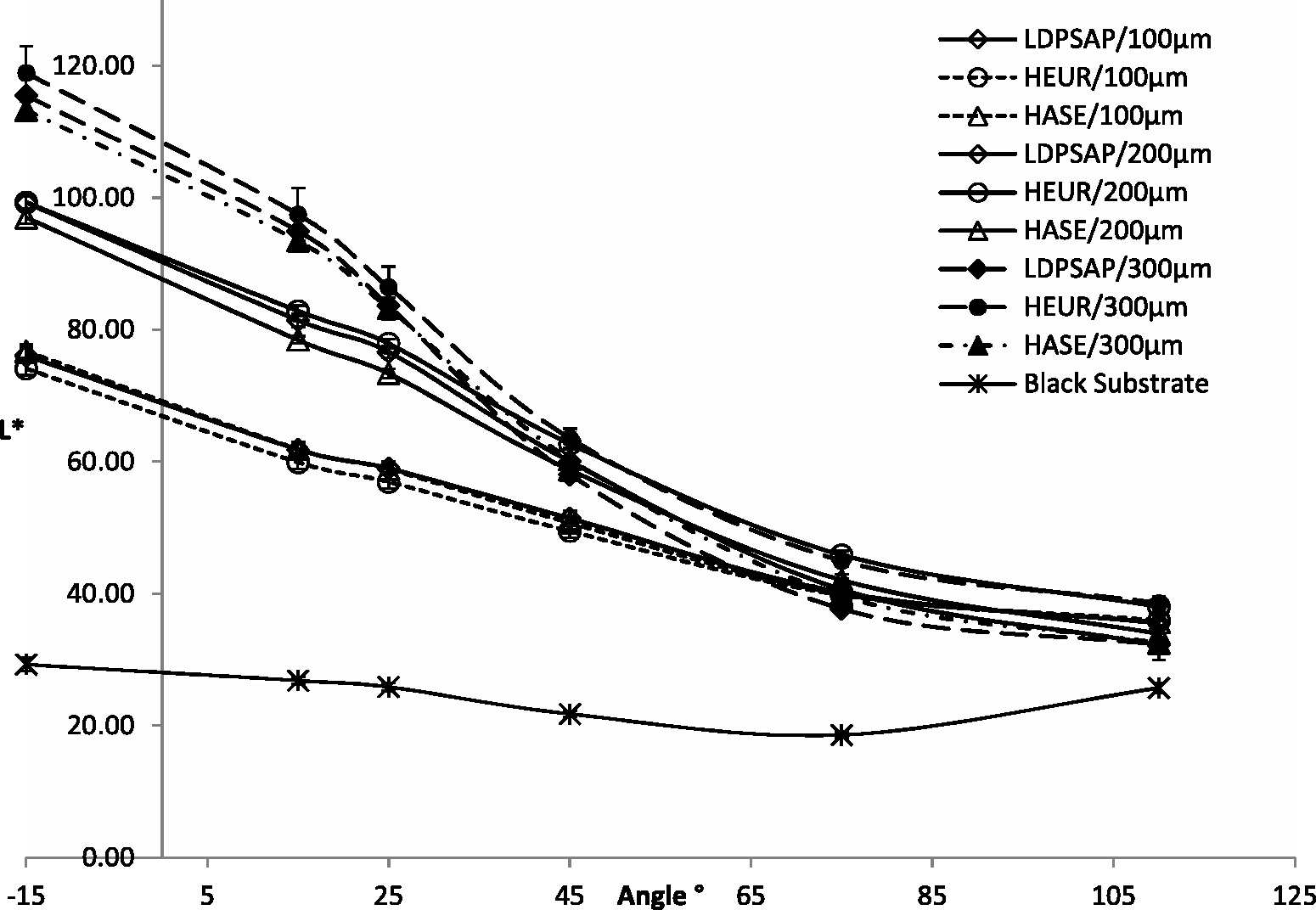
No significant differences in L*-values depending on formulation were noticed, as the standard error bars overlapped the three means within each gap height and angle. This means that the difference in solids deposit between samples depending on the chosen RM (cf. Table 3) did not significantly affect the L*-values.
The gap height had a great impact on the L*-values (increasing with increasing gap height) between –15° and 45°. This can be attributed to the increased solids deposit and an associated increase in layer thickness, rendering the samples a smoother surface, clearly seen in the SEM images in Figures 4(a)–(c). Furthermore, as suggested previously and confirmed by the cross-sectional SEM images in Figures 4(d)–(f) and also as expected, the increased solids deposit led to increased pigment concentration within the layer. Hence, it is not unexpected that a larger coating gap produced a better optical coverage of the black fabric. It should be mentioned that the 300 µm samples coated with B:EPD:HEUR exhibited surface defects, appearing in the SEM images as diagonal stripes and resulting in a standard deviation in L* being of the order of 5, decreasing with increasing detection angles. B:EPD:LDPSAP samples exhibited similar defects, although to a lesser extent, resulting in a lower standard deviation of 3. No surface defects were seen on B:EPD:HASE samples and possible causes for the appearance of these defects require a separate study.
The a*- and b*-color coordinates
The influence of RMs and gap heights on the color coordinates a* and b* is shown in Figure 7 in the case of samples coated at the lowest speed, 0.6 m/min. For all samples, the a*- and b*-coordinates formed horseshoe-shaped curves, stretching from within the blue-green quadrant (at angles between 110° and 15°) into the red-blue quadrant (at –15° angle), showing that the color of the samples varied to a great extent with increasing detection angles. The color coordinates (close to the origin) corresponding to the uncoated black substrate did, however, not vary with the detection angle. Thus, the structure of the substrate did not contribute to the greater color differences noted for the EP-coated samples. Generally, the a*-value varied the most between −15° (being more red) and 15° (becoming greener), with only small changes in the b*-coordinate. This correlates well with the angles where the greatest flip-flop effects can be visually observed, with the color changing from violet to blue. Hence, the color change is substantially governed by changes in the a*-value as well as in L* (cf. Figure 6), but considerably less by variations to b*. To some extent, this indicates that a multi-angle spectrophotometer with six detection angles, including −15°, corresponds better to the visually perceived color changes (turquoise-blue-violet), compared to one with only five detection angles, used in a previous study.
5
CIE a*- and b*-coordinates as a function of the detection angle for effect pigment coated samples produced using a coating speed of 0.6 m/min, and for plain black substrates. The samples were produced using different gap heights and rheology modifiers (RMs). The bars denote the standard deviations.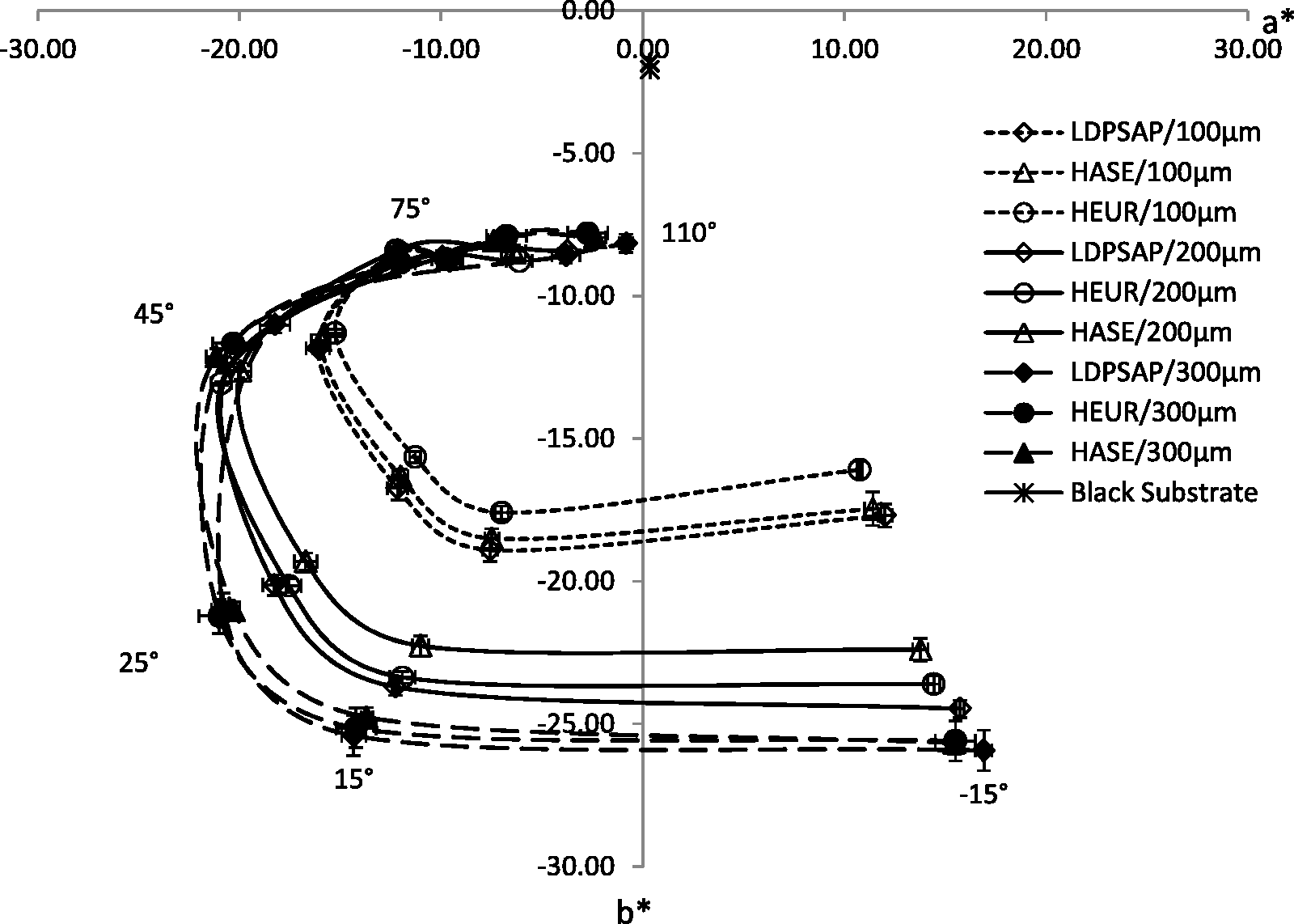
The gap heights (or solids deposits) strongly influenced the a*- and b*-coordinates, as seen in Figure 7. By doubling the gap height (from 100 µm to 200 µm), the horseshoe curves became much wider (extending over a wider region in the color plane) compared to when increasing the gap height by 50% (from 200 µm to 300 µm). Increased solids deposit leads to thicker layers containing increased numbers of EPs, improved distribution of the pigments and slightly more horizontally oriented platelets, as seen in Figures 4(d)–(f). Obviously, this led to greater color changes expressed as increased variations in the a*-values, and increased blueness of the samples, since b* decreased between −15° and 25° angles, with an increased gap height. This was in agreement with the visual impression, since the color-changing effects became more chromatic and pronounced for samples coated with larger gap heights.
The type of RM significantly influenced the a*- and b*-coordinates for the 100 µm samples, corresponding to the differences in solids deposit between the formulations (see Table 3). Similar coordinate curves were obtained with the B:EPD:LDPSAP and B:EPD:HASE samples, having similar solids deposit, 30 and 29 g/m2, respectively, whereas B:EPD:HEUR had lower amounts of only 23 g/m2. With the latter formulation, the color changes were somewhat less pronounced than in the cases of the other two. However, this trend was not observed with the 200 or the 300 µm samples, despite that the differences in solids deposit varied between 4 and 7 g/m2. It might be speculated that a threshold concentration is reached at the 300 µm gap height, with solids deposit between 71 and 82 g/m2, meaning that excessive amounts of solids deposit may not increase the color-changing effects. It is, however, difficult at this point to speculate why the 200 µm sample did not follow the same trend.
Influence of coating speed on color differences
The influence of the coating speed on the total color differences (ΔE*) at various detection angles for samples coated with each type of formulation is shown in Figure 8. Generally, the L*, a* and b*- values indicated that samples coated at the lower speed (0.6 m/min) were slightly lighter and more chromatic. An increased solids deposit followed the same trend, generating lighter and more chromatic color changes (see Table 3, Figures 6 and 7). Here, the reference values used for the evaluation were the color coordinates for the samples coated at the lower speed.
The total color differences ΔE* at various detection angles between samples coated at low (0.6 m/min) and high (12 m/min) speed for all formulations and gap heights. Error bars represents the standard deviations.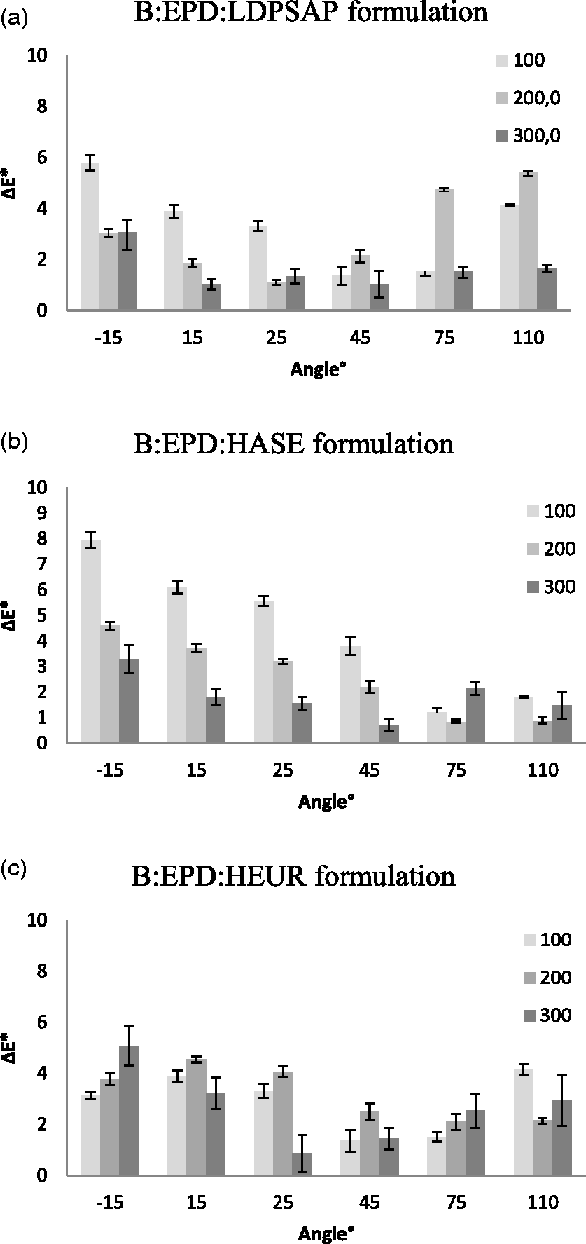
The highest ΔE*-values were noted for the B:EPD:LDPSAP and the B:EPD:HASE samples coated with a gap height of 100 µm (Figures 7(a) and (b)). This can be related to the solids deposit differences, which were higher between samples with smaller gap heights. The decreasing ΔE*-values with increasing gap heights can be related to the higher pigment concentrations within the increased coated layers, leading to increased covering of the substrate surface, resulting in smaller differences between low and high coated samples. It is also evident that the relative thickness difference of the coating layer between samples coated at low and high speeds was smaller when increasing the gap. The reason why the ΔE*-values were relatively small for the B:EPD:HEUR samples coated with a gap of 100 µm (and then increased with increasing gaps) could possibly be associated with the small differences in solids deposits between these samples.
The ΔE*-values tended to decrease with increasing gaps for B:EPD:LDPSAP and B:EPD:HASE samples in the angle range −15° to 25° and −15° to 45° angles, respectively (Figures 8(a) and (b)). This indicates that the greatest color differences between low- and high-speed coated samples should be easiest to detect at the −15° angle, which was also visually confirmed in diffuse illumination. Figure 8 shows that the ΔE*-values varied significantly depending on the solids deposit and the detection angle. However, it also points to the complexity in performing visual observations associated with angle-dependent color changes. Thus, it is difficult to speculate on whether or not the smaller ΔE*-values (below two units) between samples coated with the same gap heights can be perceived by the human eye.
Conclusion
Adding small amounts of different types of RMs (exhibiting different thickening mechanisms) compensated for the reduction in the shear viscosity of the formulation, caused by adding EPD to the binder. This will promote storage stability and prevent bleed through the woven fabric. LDPSAP provided the highest viscosity at lower shear rates and a more pronounced shear thinning behavior than HASE and HEUR, which had the ability to form associative networks, withstanding higher rates better. The type of RM used affected the solids deposit, which at the lower coating speed followed the viscosity differences between the formulations. A higher viscosity was associated with a higher solids deposit.
A strong correlation was noted between an increased layer thickness (depending on gap height) and an improved surface smoothness and pigment dispersion, as well as more horizontally oriented pigments within the coated layer, as revealed by SEM studies. However, no clear effects of the coating formulation or coating speed on the pigment distribution or pigment orientation within the coated layer could be noted.
The amount of pigments within the coated layer is suggested to be crucial for the color variations between samples coated at different speeds. Increased amount of solids deposit, generated by using larger gaps between the knife and fabric in combination with low-speed coatings, generally provided lighter and more chromatic samples. This resulted in more pronounced angle-dependent color-changing effects, detected by the multi-angle spectrophotometer with six detection angles.
The results indicate that the performance of EP coatings on textiles can be optimized by choosing a RM used within this study combined with suitable knife-coating parameters in the form of increased gap heights and lower coating speeds.
Footnotes
Funding
This work was supported by the R&D Board at the University of Borås.
Acknowledgments
The authors thank Mikael Rigdahl (Material and Manufacturing Technology, Chalmers University of Technology) for scientific guidance. Thanks to Erikha Emanuelsson at the Department of Perceived Quality for the spectrophotometer measurements at Volvo Car Corporation, Sweden.