
Abstract
A three-dimensional computational model is established to simulate the air flow patterns in the rotor spinning unit of a rotor spinning machine. The effects of rotor speed, rotor diameter and rotor slide wall angle on air flow characteristics and hence yarn properties are investigated. The airstream accelerates from the transfer channel inlet to the outlet. There are velocity differences in both the cross-section and along the transfer channel, causing hooked fibers to straighten. The airstream swirls around the rotor at a high speed. However, vortices that can cause fiber curving and buckling are formed inside the rotor. The effect of rotor speed is significant. There are more vortices near the wall at a lower rotor speed, while too large a rotor speed can lead to an excessive centrifugal force, thus increasing yarn breakages. The rotor diameter affects the flow characteristics in a way similar to that of rotor speed. As a smaller slide wall angle generates higher velocities in the transfer channel and more stable velocities in the rotor groove, a small angle is preferable. Computational modeling has provided a useful insight into the rotor spinning flow pattern, thus it can be used to optimize the rotor design to produce better rotor spun yarn.
Rotor spinning has gained its popularity all over the world due to the advantages of the lower cost of production and amenability to automation. Despite its positive aspects, it is universally accepted that rotor spun yarns have been restricted to coarse and medium counts. Generally, the tenacity of rotor spun yarn is lower than that of ring spun yarn of comparable cross-section, which is due to the differences in processing method and yarn structure.1,2 In rotor spinning, fibers combed by the opening roller are transported to the rotor by the air flow. In the process of transportation, fibers may alter their configurations at different stages because of the impact of air flow on fiber orientation. For example, fibers can potentially be affected by turbulence as they flow through the transfer channel, which can eventually lead to the deterioration of yarn quality. It is therefore extremely important to make it clear how the air flow moves and how it affects fiber movements and hence yarn properties in the rotor spinning unit to produce yarns with the desired quality.
According to previous studies, there are four major components of the rotor spinning unit that influence yarn properties obviously, including the opening roller, the transfer channel, the rotor and the navel. The speed of the opening roller has a bearing on fiber separation quality and then yarn properties. Kong et al. 3 indicated that an increase in opening-roller speed from 5000 to 7000 rpm could decrease the number of yarn imperfections and the CV%, while a further increase in opening-roller speed may lead to the deterioration of yarn quality due to fiber breakage. A tapered structure is used in the transfer channel in order to improve fiber straightening during transfer from the opening roller. Lawrence and Chen 4 proposed three mathematical models to optimize the design of a transfer channel with a rectangular cross-section. They indicated that the optimum design by the proposed model gave a threefold improvement in the straightening of fibers compared with a commercial design. Seyed et al. 5 studied the effect of the design of the fiber exit edge on the transfer channel on yarn properties in a slotted model similar to R20 of Rieter. They examined nine designs of fiber exit edge and reported that a reduction of the slot width can improve yarn properties significantly. The rotor, the key component of the rotor spinning unit, plays an important role in fiber strand collecting and yarn twisting. Both rotor speed and rotor diameter influence yarn properties markedly.6–8 Manohar et al. 7 demonstrated that most of the yarn properties showed a deterioration with increase in rotor speed, and the imperfections, which are really wrapper fibers in yarns, increased at higher rotor diameters. However, in Koç and Lawrence’s report, 8 it was indicated that increasing the rotor diameter decreased the wrapper fibers for different rotor speeds. They also declared that with increasing rotor speed yarn tenacity increased for a rotor diameter of 32 mm, while it fell down as the rotor diameter increased to 40 mm. It is understood that rotor speed and rotor diameter affect yarn properties in a complex way. Other factors, including negative pressure inside the rotor 9 and the carding technique6,10 shall also be optimized together with those discussed above to produce better yarn quality at the highest possible speed and with minimum waste. Actually, most of the factors greatly affect fiber configurations and, subsequently, yarn properties by influencing air flow characteristics inside the rotor spinning unit. Therefore, effective control of the air flow will ensure both yarn quality and the productivity and economy of the spinning process.
Computational methods play a vital role in appropriately presenting the characteristics of the actual flow. It is, undoubtedly, an effective method to study the air flow in rotor spinning. Kong and Platfoot11,12 first introduced Computational Fluid Dynamics (CFD) analysis into rotor spinning. They developed a two-dimensional numerical model of the transfer channel to study the flow pattern. They indicated that the changes in geometry of the transfer channel and spinning operation parameters would lead to an alteration in strength and area of recirculation at the inlet of the transfer channel, which were closely related to fiber configurations. The air flow inside the rotor spinning unit is extremely complex, and studies of the air flow characteristics are, however, rather scarce, especially inside the rotor.
In the present work, we aim to provide more studies about the air flow characteristics in the rotor spinning units, especially that inside the rotor. We simulate the air flow field in the rotor spinning unit, and analyze the effect of the processing and geometric parameters of the rotor on the characteristics of the air flow field, and consequently on the yarn properties. The simulation results are then compared with our experimental data and the experimental results obtained by other researchers.
Model construction
Rotor spinning unit structure
In the Air Suction Open-end Rotor Spinning, the internal air is sucked by an air pump, thus forming a negative pressure zone in the rotor, then two external airstreams are fed into the rotor from the transfer channel and the yarn guiding mouth, respectively. The air flow coming from the transfer channel conveys the fibers to the rotor, which greatly influences the fiber straightness and parallelism.
In this research, the computational domain considered in the simulation process is the interior of the transfer channel from the inlet to the outlet and the rotor, including the doffing tube. A three-dimensional (3D) geometric model of the computational domain of the spinning unit, as illustrated in Figure 1, is developed in the Cartesian coordinate system, of which the origin O is located at the bottom center of the rotor. Perpendicular to the rotor bottom is the y-axis, while the x-axis is taken as the direction parallel to the yarn guiding mouth. The main geometric parameters of the spinning unit are the height of the rotor outlet h (1 mm), the height of the rotor H (12 mm), the diameter of the yarn guiding mouth d (1 mm), the rotor diameter D (36 mm) and the angle of rotor slide wall θ (66°). Furthermore, a V-shaped fiber-collection surface (the rotor groove) is used.
Profiles of the three-dimensional model of the rotor spinning unit.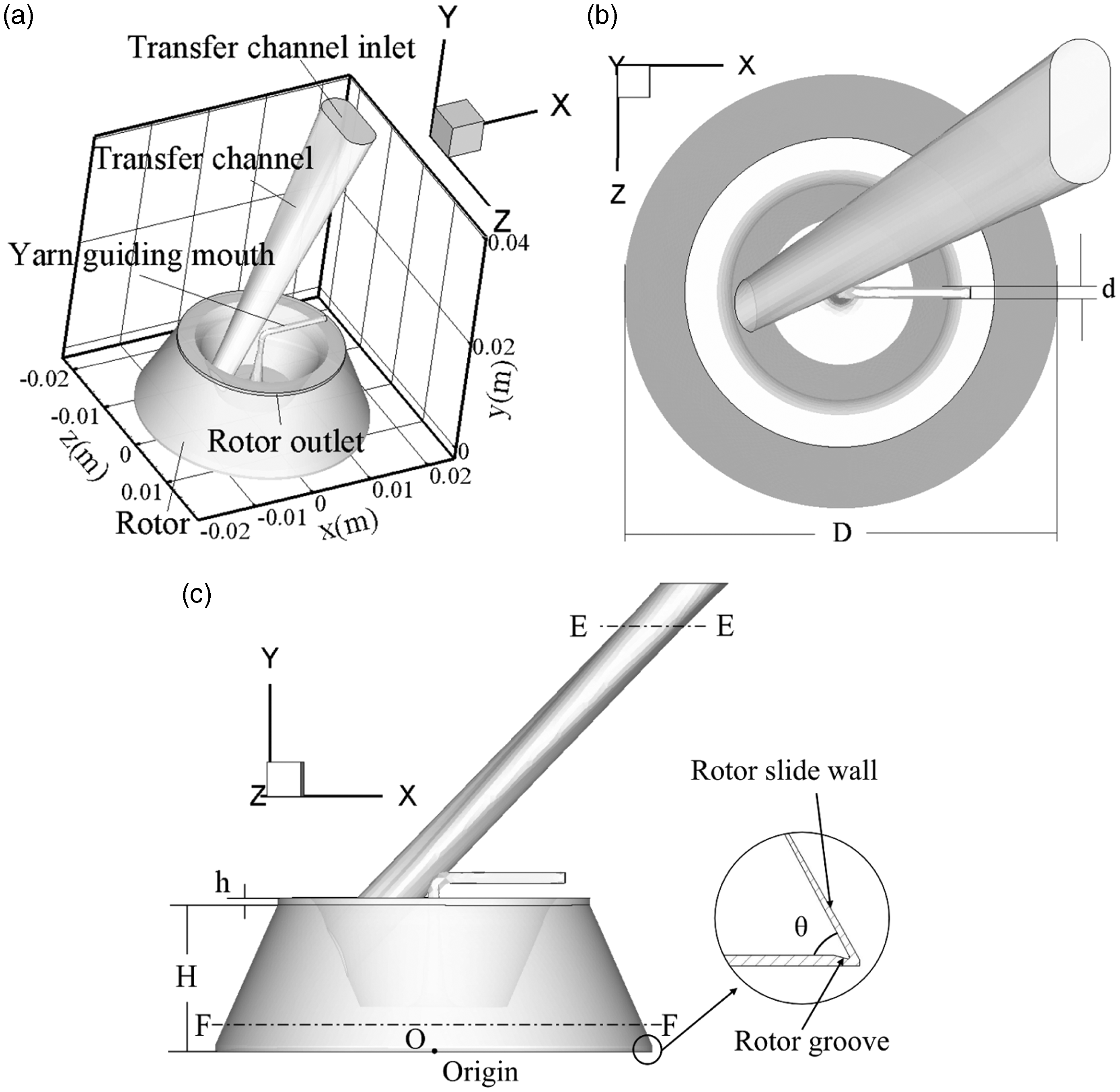
Governing equations
The rotor spinning unit is small in size and the fiber transport and collecting process is completed in a short time, hence we assume that there is no heat transfer in the spinning process. Since the Reynolds number in the rotor spinning unit is large (up to 6000), 11 the calculation should be performed based on a turbulence model. In addition, the velocity at the transfer channel inlet is generally less than 100 m/s according to our experimental results, thus the Mach number in this zone is no more than 0.3 so that the air flow is considered as incompressible. Therefore, the air flow in this zone can be assumed as a viscous, incompressible and isentropic turbulence flow.
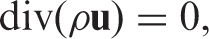
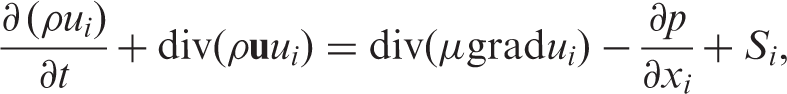
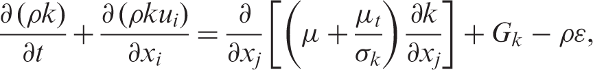
The governing equations, including the mass conservation equation and the momentum conservation equation, can be expressed as
Turbulence model
The standard two-equation
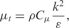
The standard two-equation
Grid generation
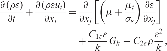
The GAMBIT software, as a pre-processor of CFD simulation, is used to mesh the 3D model mentioned above. A mix of structured hexahedral cells and unstructured tetrahedral cells is applied in the computational domain (see Figure 2). To satisfy the wall functions, the grids in the near-wall region are denser than the other regions. Generally, the first grid should be established inside the layer of logarithmic law.
Computational grid and boundary conditions for the simulation.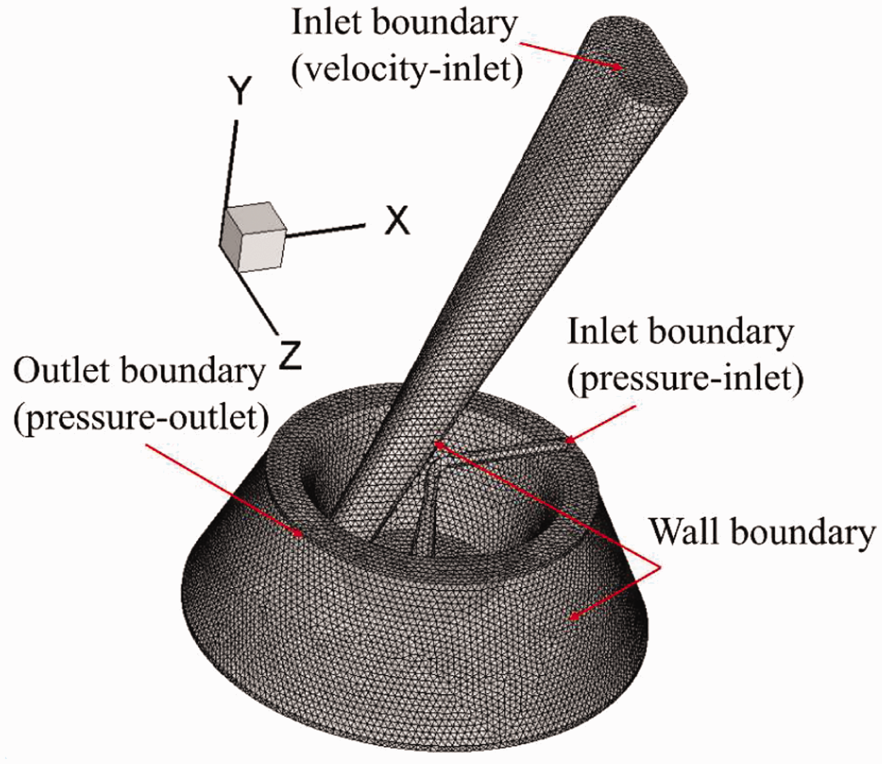
Boundary conditions
The inlet boundary
The external air currents from the transfer channel and the yarn guiding mouth flow into the rotor as air supply. The airstream coming from the transfer channel plays an important role in conveying the fibers to the rotor, and therefore the velocity of the transfer channel inlet should be larger than the surface velocity of the opening roller in order to peel off the fibers smoothly. Then, the transfer channel inlet can be set as velocity-inlet. Because the yarn guiding mouth is open to the atmosphere, the pressure inlet condition is used and the pressure is equal to the atmospheric pressure (1.01 × 10⁵ Pa).
The outlet boundary
The air in the rotor is sucked by an air pump, thus a zone of negative pressure inside the rotor is formed. The rotor outlet is set as pressure-outlet with the suction pressure adjustable, which is an important variable that affects spinning efficiency and yarn quality.
The wall boundary
The nonslip boundary condition is applied at the wall. The revolving rotor generates centrifugal force acting on the fiber strands in the rotor groove to guarantee the spinning, and hence the rotational speed of the rotor is set.
Solution procedure
A commercial CFD package, FLUENT, was used to carry out the numerical simulation in this work. The finite volume discretization method was presented and the second-order-upwind scheme was adopted due to its high accuracy to solve the governing equations.
Results and discussion
Grid test for mesh independency
The computational results are greatly affected by the scheme of mesh generation. Generally, grids with high quality can not only improve the accuracy of calculation, but also reduce the computation time. Therefore, extensive computational tests were conducted in order to find the optimal grid scheme. We contrasted three different grid schemes: 339329 (Grid 1), 253679 (Grid 2) and 208729 (Grid 3) cells (shown in Figure 3). Little difference is shown in the figures by all the three schemes. Hence, taking the computational efficiency into account, Grid 2 is adopted in the subsequent computations.
Comparision of velocity profiles for the three different grid schemes: (a) along the x-axis at distance of y = 2 mm, (b) the centerline along the y-axis.
Flow characteristics
According to the model described above, we computed the air flow inside the rotor spinning unit close to the conditions used in the actual spinning process. The inlet velocity was 20 m/s, and the rotor spins clockwise at a speed of 60,000 rpm. Furthermore, the outlet pressure was –7000 Pa.
As can be seen from Figure 4(a), the air is sucked out from the rotor by the air pump, thus forming a negative pressure zone inside the rotor, and then the external airstreams from the transfer channel and the yarn guiding mouth flow into the rotor. The pressure is changing along the transfer channel. The pressure at the transfer channel inlet is a positive pressure, while it drops down gradually to 6000 Pa of negative pressure at the transfer channel outlet. The pressure in the rotor keeps in the range of 3000–7000 Pa of negative pressure. The negative pressure inside the rotor drives the airstream to flow from the transfer channel inlet into the rotor, which transports the fibers peeled off from the opening roller to the rotor groove.
(a) Pressure distribution and (b) velocity vectors of the rotor spinning unit.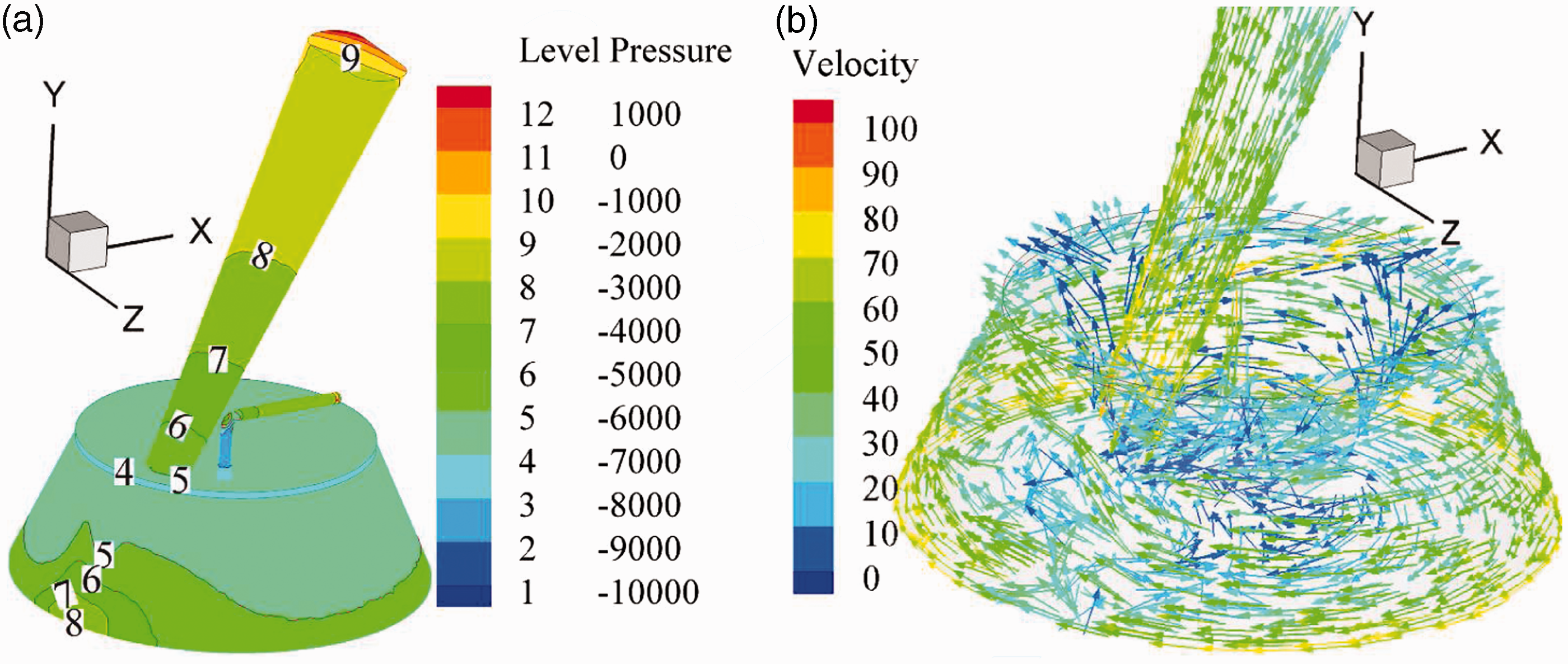
Figure 4(b) illustrates the velocity vectors of the whole computational domain of the rotor spinning unit. Due to the use of a tapered configuration on the channel, the airstream accelerates from the transfer channel inlet to the outlet. The velocity reaches its maximum at the transfer channel outlet and then drops down. The rotating rotor drives the airstream to rotate clockwise. After one circle round the rotor, the rotating airstream mixes another airstream coming from the transfer channel, forming a vortex flow in the vicinity of the transfer channel outlet, which leads to fiber buckling. The air swirls while it flows upstream with a decreasing velocity. It then flows out from the rotor outlet.
The transfer channel
Figure 5 shows the flow characteristics inside the transfer channel. Figure 5(a) shows the velocity distribution in the transfer channel cross-section (Section E-E in Figure 1(c)), and Figure 5(b) shows the velocity distribution along the central axis of the transfer channel from the inlet to the outlet. As shown in Figure 5(a), there is a velocity difference in the cross-section of the transfer channel. The velocity difference generates frictional interactions between the fibers, since those fibers in the same cross-section will travel with different velocities. A larger velocity difference will appear to improve fiber configurations in the transfer channel due to the increase of the drag force on the fibers, which is responsible for the curved fiber straightening. The velocity at the outlet of the transfer channel is almost five times that at the inlet (see Figure 5(b)). According to Chattopadhyay and Sarkar,
13
the accelerating air flow in the transfer channel results in different speeds at the leading and trailing ends of the moving fiber, thus causing hooked fibers to straighten. Therefore, the velocity difference along the transfer channel can also assist in straightening fibers.
Velocity distributions of the transfer channel: (a) the centerline of cross-section E-E (see Figure 1(c)) at distance of y = 35 mm; (b) the central axis of the transfer channel from the inlet to the outlet.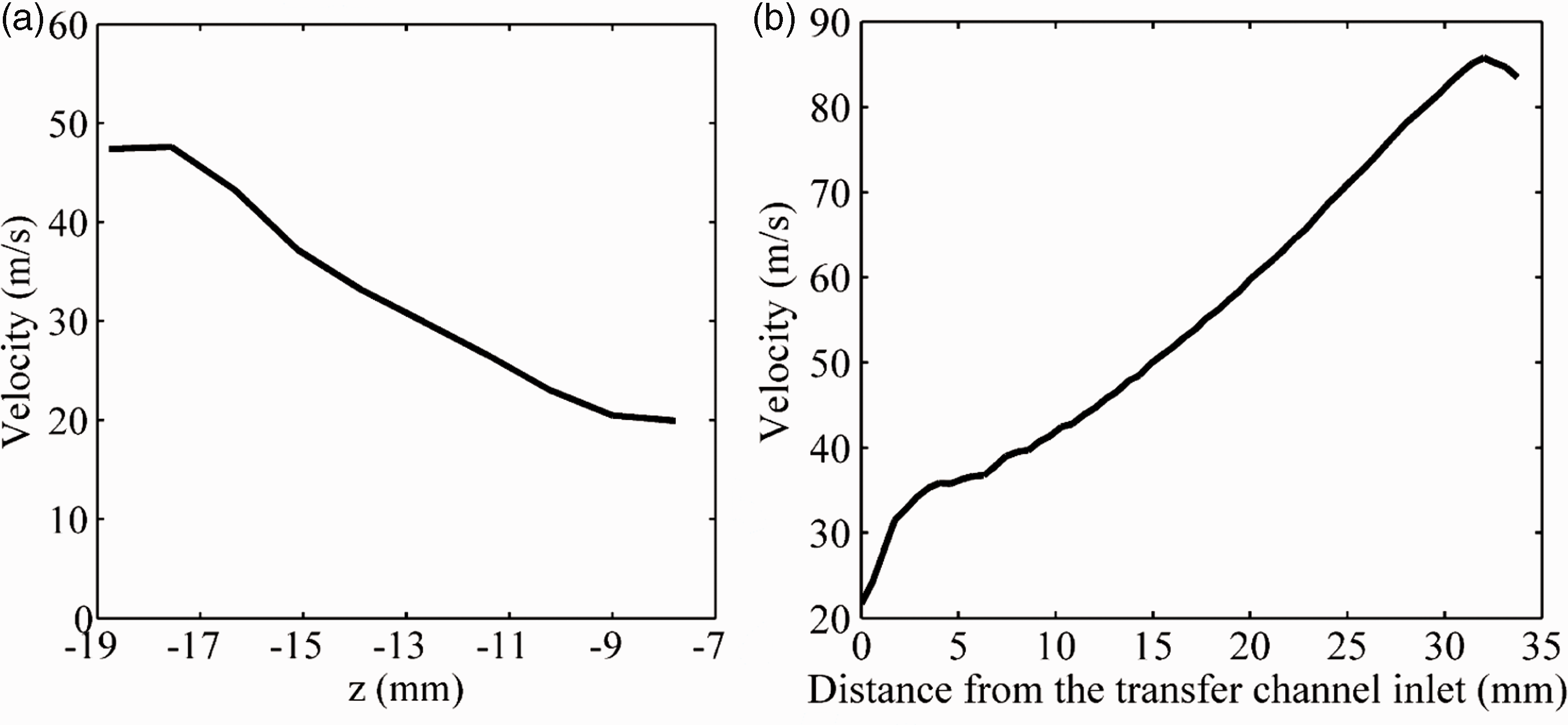
The rotor
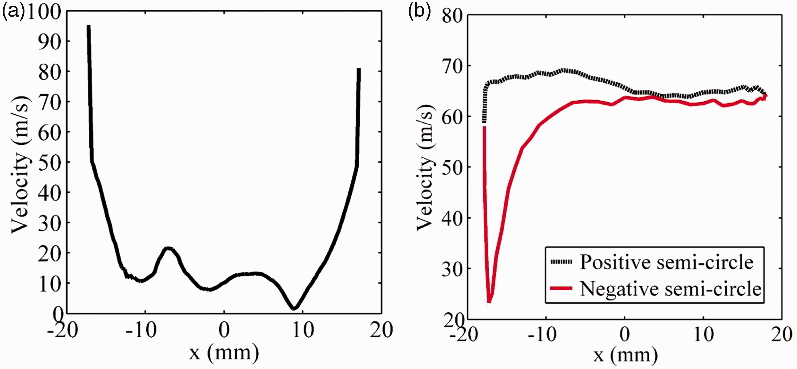
Figure 6 shows the velocity vectors inside the rotor. As soon as the accelerated airstream coming from the transfer channel reaches the rotor, it becomes a swirling current around the rotor wall (region A) owing to its collision with the wall surface and the suction of the pump. The swirling air benefits fiber collection. Due to the impact of the airstream on the rotor wall at position D, a vortex is generated in region B. After a circle around the rotor wall, the airstream meets the air coming from the transfer channel at position D. The impact of these two strands of air flow creates a significant reverse flow in region C. When flowing toward the rotor wall, the air flow in the center region changes its direction as soon as it meets the air flow around the wall. The reason for the sudden change in the flow direction is that the velocity in the center region is much lower than that around the wall, which is shown in Figure 7(a). The velocity near the wall reaches over 90 m/s, while in the center region it drops down to an extremely low level, below 10 m/s. Figure 7(b) shows the velocity distribution around the rotor groove (see Figure 1). It is found that the velocity in the positive semi-circle (0 < z < 18 mm) remains at a stable level with a velocity of 65 m/s. However, the velocity varies greatly in the negative semi-circle (–18 mm < z < 0). The velocity at the position very near the wall (x = –17 mm) reduces to a value lower than 30 m/s, whereas it increases to 60 m/s at x = –10 mm. Actually, the position where the minimum velocity occurs is right against the transfer channel outlet. This indicates that although the airstream accelerates in the transfer channel and reaches a high velocity of about 90 m/s at the outlet, it slows down rapidly as soon as it enters the rotor (see also Figure 5(b)).
Velocity vectors of the cross-section of the rotor at the distance of y = 3 mm (i.e. section F-F in Figure 1(c)). Velocity profiles inside the rotor: (a) at the position z = 0 in the y = 2 mm plane; (b) along the circle of the rotor groove center (positive semi-circle: 0 < z < 18 mm, negative semi-circle: –18 mm < z < 0).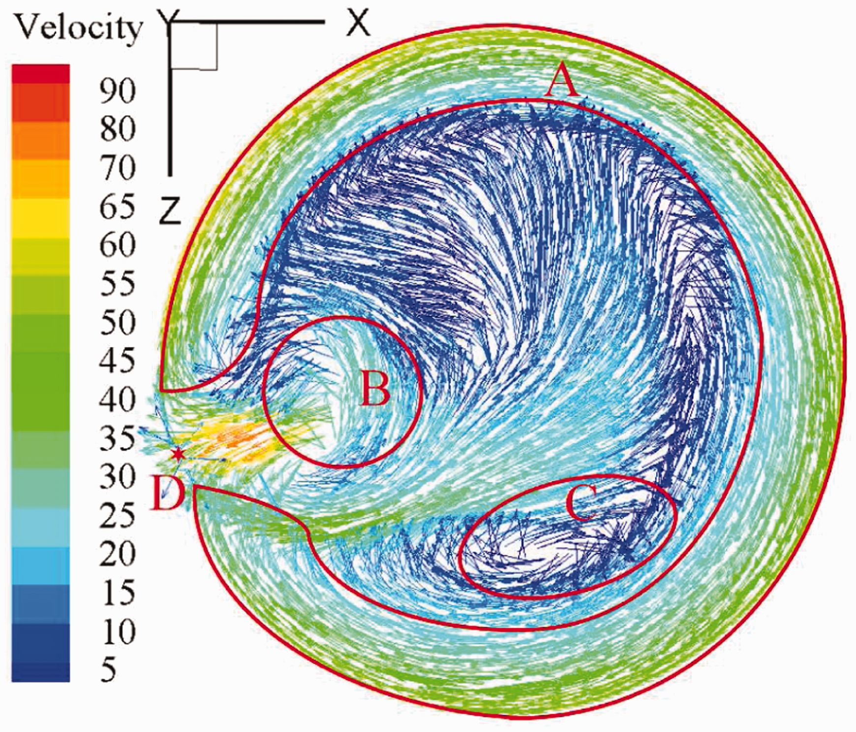
Air flow field measurement verification
To verify the validity of this simulation for the case described above, the air flow field of the rotor spinning unit was measured. Since the rotor is a high-speed rotating sealed structure, it will be difficult to measure the velocity directly with the velometer in the spinning state. The pressure, however, is another critical parameter characterizing the gaseous state, and therefore is chosen as a comparison parameter. For simplicity in the measurement, the measurement is conducted while the spinning unit is in the shut-down state.
A sketch of the measurement system used for studying the pressure in the rotor is shown in Figure 8. The control valve is used to control the suction pressure, namely, the dynamics of the air pump. By using the flow meter, the volume flow rate at both the outlet and inlet of the spinning unit can be obtained. One end of a thin tube was connected with the U-tube manometer, while the other end was inserted into the yarn guiding mouth in order to obtain the internal pressure at different positions. Meanwhile, the diameter of the yarn guiding mouth was so small that it was closed in order to reduce the experimental errors. We selected the measuring points horizontally (x-direction) and vertically (y-direction). An interval of 1 millimeter between the measuring points was set. Restricted by the experimental conditions, only the negative direction of the x-axis (the direction toward the transfer channel outlet) was tested. Therefore, a total of nine points was tested in each direction with the outlet pressure of –6000 Pa and –7000 Pa, respectively, and the horizontal length and the vertical length were both 8 mm.
Sketch of the measurement system.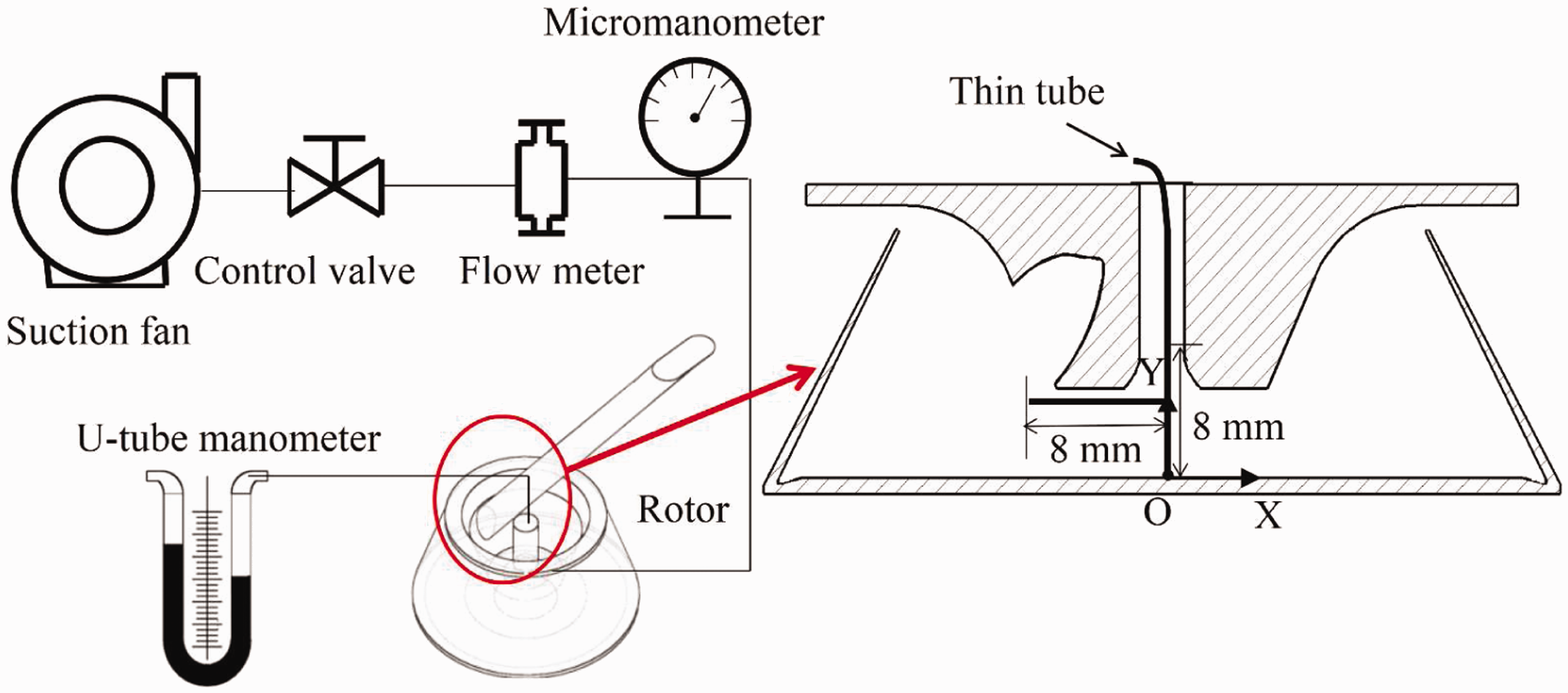
The numerical simulation was performed based on the experimental conditions, thus only one inlet boundary (i.e. the transfer channel inlet) was considered. The rotor speed was set as 0.
The measured pressures inside the rotor are compared with the simulation data under the same conditions. The results are shown in Figure 9. Although the computed values are a little higher than the measured data in both directions, the simulation results agree well with the measuring ones qualitatively. We attribute the difference between the measured and simulation values to the pressure loss in the outlet tube. During the experiment, the micromanometer is located near the air pump and, consequently, the working pressure (the actual pressure inside rotor) is lower than the design pressure adopted in the outlet boundary. However, in a qualitative sense, the simulation predicts the pressure distributions quite well, as seen from the figures.
Comparision of the computed pressures with the experimental results in (a) the horizontal direction and (b) the vertical direction.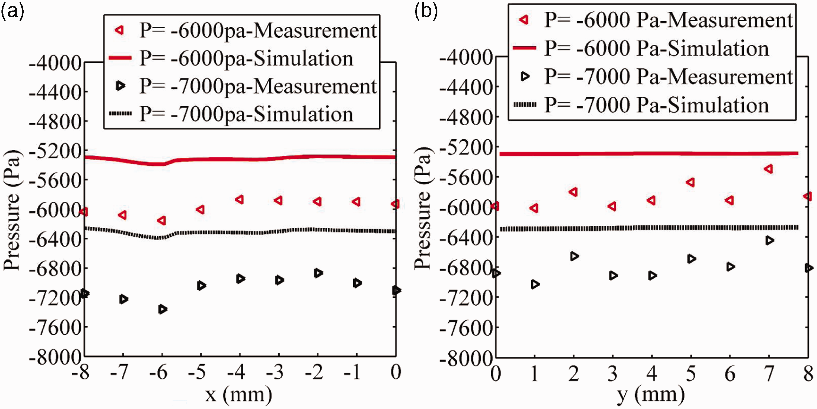
Effect on flow characteristics and yarn properties
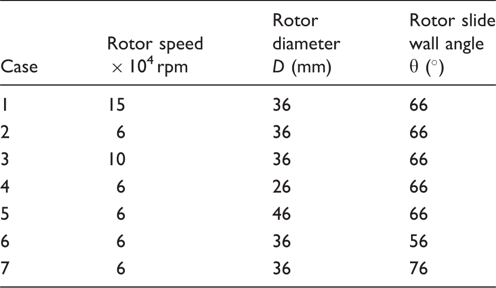
Specifications of rotor design
Effect of rotor speed
As regards to rotor speed, Figure 10 demonstrates the velocity distributions along the axis of the transfer channel with three different rotor speeds. It is observed that the velocity distributions are quite similar among these cases. However, the velocity in Case 3 is a little higher than that in the other two cases in the downstream region of the transfer channel.
Effect of rotor speed on velocity distributions along the axis of the transfer channel.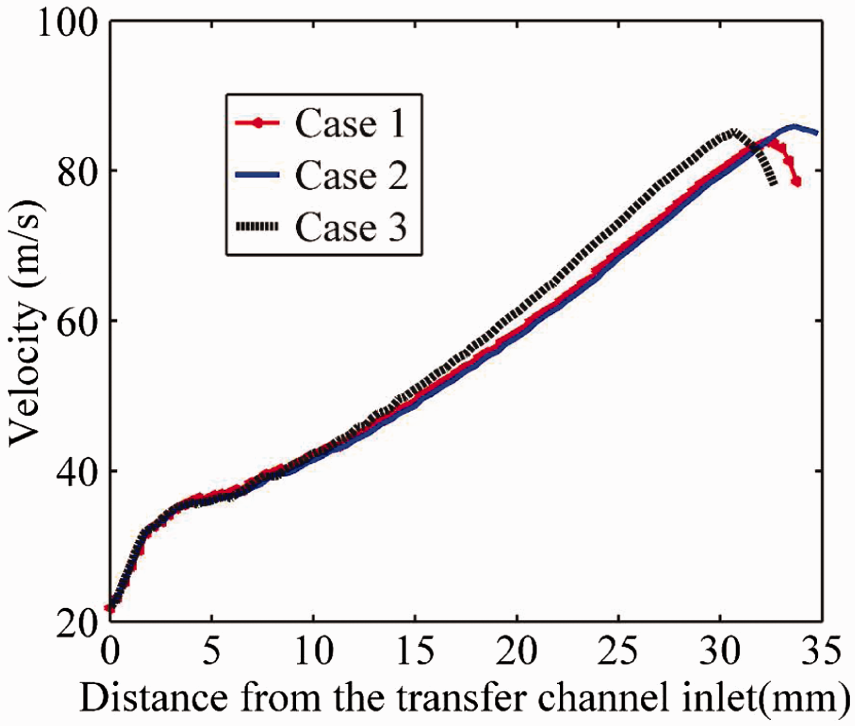
The effect of rotor speed on flow characteristics in the rotor is quite complex. As shown in Figure 11(a), the velocity distribution rules inside the rotor are similar among these three cases. The velocities are low in the central regions, while they increase to high levels near the rotor slide wall, which can be obviously observed in Case 1 (rotor speed = 150,000 rpm). The velocity near the slide wall increases apparently as the rotor speed is increased. It is almost thrice as high in Case 1 as that in Case 2 (rotor speed = 60,000 rpm). This indicates that the centrifugal force, which is proportional to the square of rotor speed and rotor diameter,
7
is much larger in Case 1 than that in Case 2. Since the airstream flows at a stable level in the positive semi-circle of the rotor (see Figure 7(b)), Figure 11(b) only shows the velocity distribution of the negative semi-circle of the rotor groove. It can be seen from the figure that the velocities around the rotor groove in Case 1 and Case 3 remain stable at 140 and 90 m/s, respectively. However, there is a minimal velocity (about 20 m/s) in Case 2 at position x = –17 mm. As the minimal velocity appears either in the vortex center or at the edge of the vortex, it indicates that more vortices are generated in Case 2 than that in the other two cases.
Velocity profiles in the rotor : (a) at the position z = 0 in the y = 2 mm plane; (b) along the negative semi-circle of the rotor groove center (–18 mm < z < 0).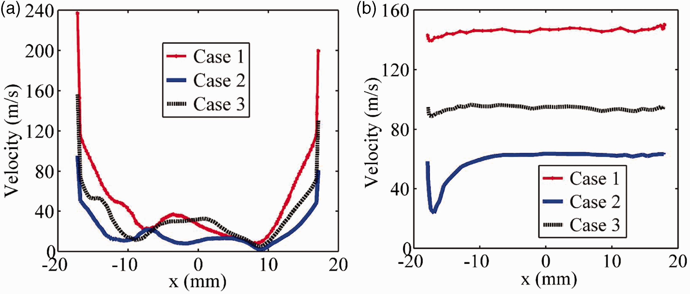
Rotor spun yarn is constructed of two zones – core fibers and wrapping fibers. 14 In accordance with Koç and Lawrence, 8 a fiber in the rotor groove wrapping around the body of the yarn rather than being twisted into the yarn is most likely to become a bridging (wrapper) fiber. The surface structures of rotor spun yarns are classified into seven categories. It is reported that orderly and loose wrapping fibers occur most frequently in yarns. 15 However, only the fibers that are orderly and tightly wrapped can improve yarn tenacity effectively.
The velocity around the rotor groove is responsible for generating more straight fibers in the convergence process and orderly wrapping fibers in twisting. The occurrence of vortices near the rotor groove can be a potential source for fiber curving and buckling. This is because the vortices will force the fibers to deviate from the rotor groove and then move along the vortices. Therefore, a larger rotor speed, which produces a higher and more stable velocity around the rotor groove, benefits fiber configurations and yarn tensile properties. In addition, the centrifugal force should be large enough to generate twist retention and false twist effect on the navel. Thus, it is suggested that a larger rotor speed be adopted as long as the centrifugal force is no larger than yarn tension.
Effect of rotor diameter
In rotor spinning, rotor diameter is important since it not only determines the spinning fiber length but also has a limitation on rotor speed and, consequently, yarn production. In this paper, we studied three different rotor diameters: 26 mm (Case 4), 36 mm (Case 2) and 46 mm (Case 5). The effect of rotor diameter on the velocity distributions along the axis of the transfer channel is illustrated in Figure 12. It turns out that a smaller rotor diameter has a considerably larger velocity in the transfer channel. The velocity in Case 5 (D = 46 mm) is slightly higher than that in Case 2 (D = 36 mm) in the upstream of the transfer channel.
Effect of rotor diameter on velocity distributions along the axis of the transfer channel.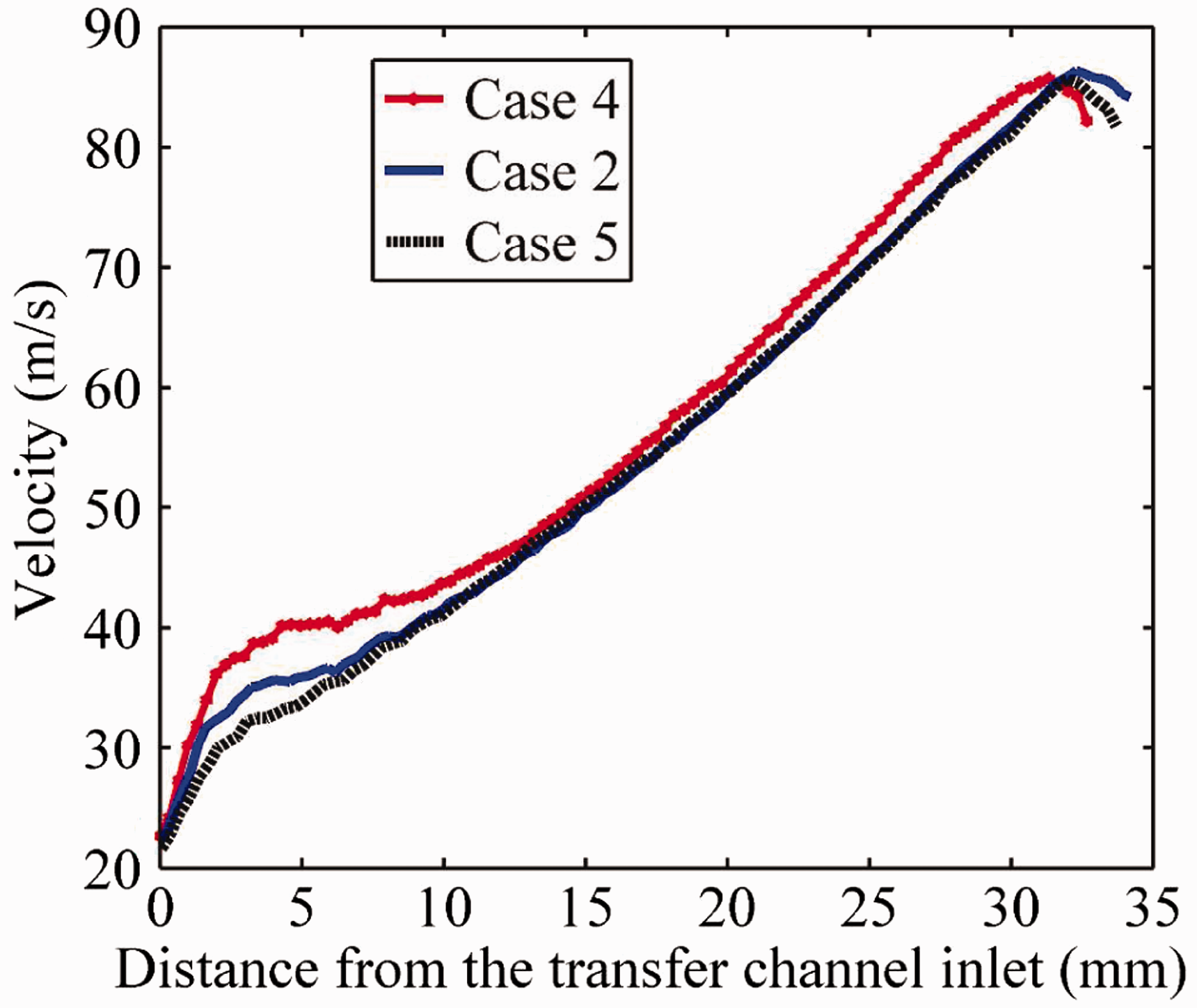
The rotor diameter has an obvious impact on rotor flow characteristics, which is shown in Figure 13. It is clear that the higher velocity near the wall is produced with a larger rotor diameter, while the velocity distribution rules in the central regions are similar (Figure 13(a)). It can be drawn from Figure 13(b) that the velocity along the negative semi-circle of the rotor groove in Case 5 (D = 46 mm) levels out at 80 m/s. Obviously, when the rotor diameter decreases to 26 mm, the velocity fluctuates markedly from 60 to 10 m/s. In addition, three minimal values in Case 4 indicate that it is more likely for a smaller rotor diameter to produce vortices.
Velocity profiles in the rotor: (a) at the position z = 0 in the y = 2 mm plane; (b) the negative semi-circle of the rotor groove center (–18 mm < z < 0).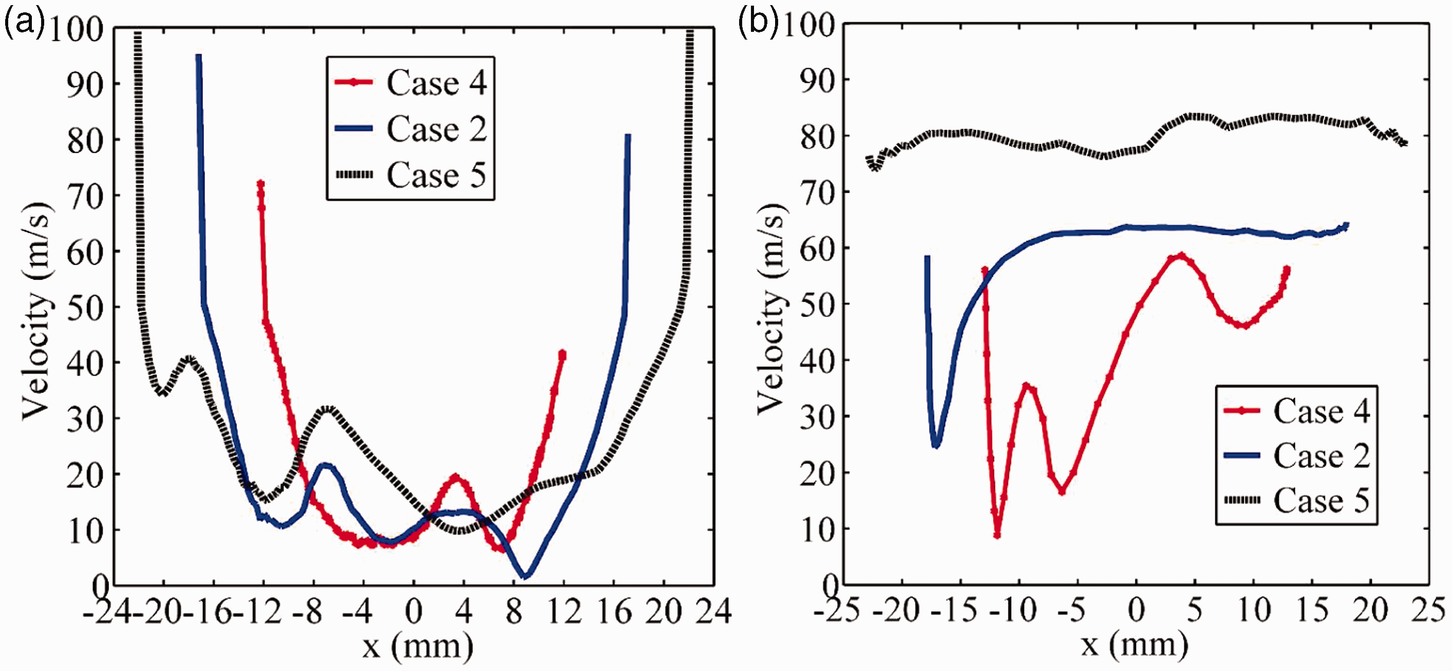
Rotor diameter always affects yarn properties together with rotor speed. 8 Actually, they affect the flow characteristics in a similar way. From our simulation results, a smaller rotor diameter is good for fiber transport owing to a higher velocity in the transfer channel. Nevertheless, the vortex intensity near the rotor groove is higher in a smaller rotor diameter (26 mm), which will degrade yarn uniformity and increase yarn imperfections. Conflicting issues must be also considered in order to determine the optimum rotor diameter. The centrifugal force cannot be too larger so as to avoid yarn breakages.
Effect of rotor slide wall angle
The rotor slide wall angle is another important factor that affects fiber configurations during spinning. Comparison of Case 6, Case 2 and Case 7 shows that as the rotor slide wall angle decreases, although the velocity in the upstream of the transfer channel almost does not change, it increases in the downstream region (Figure 14).
Effect of the rotor slide wall angle on velocity distributions along the axis of the transfer channel.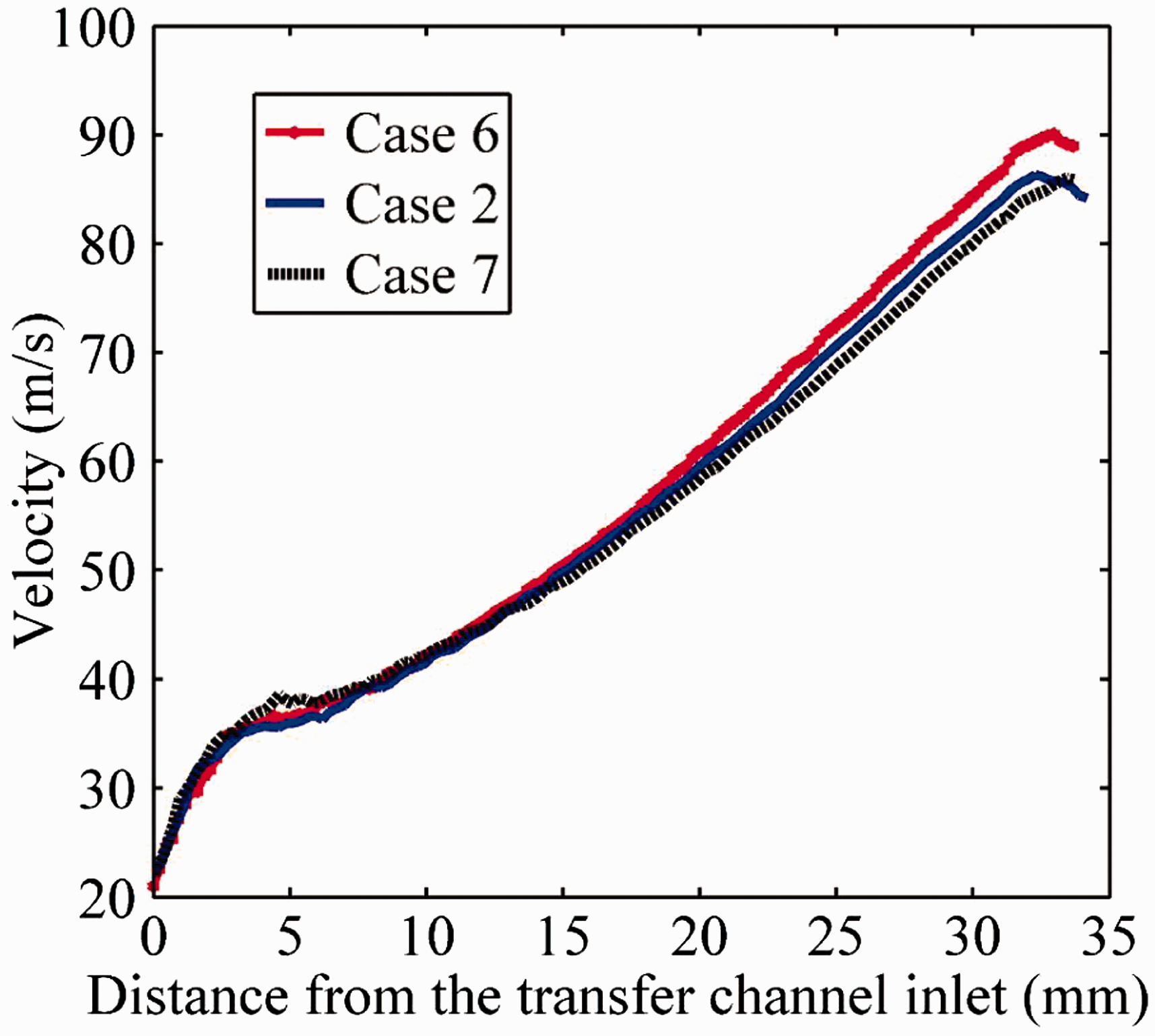
As shown in Figure 15(a), the velocity near the wall is a little higher with a smaller slide wall angle. The velocity distributions are almost the same in the positive x-axis, while there is a slight difference in the opposite direction. From Figure 15(b), it is observed that the distribution rules along the rotor groove are similar with different slide wall angles. However, the lowest velocity reduces with an increasing slide wall angle. The sudden drop in velocity may cause fiber buckling and curving easily and, consequently, deteriorate yarn properties. Our simulation results suggest that a slide wall angle no more than 76° is better for fibers to move in a stable state.
Velocity profiles in the rotor: (a) at the position z = 0 in the y = 2 mm plane; (b) the negative semi-circle of the rotor groove center (–18 mm < z < 0).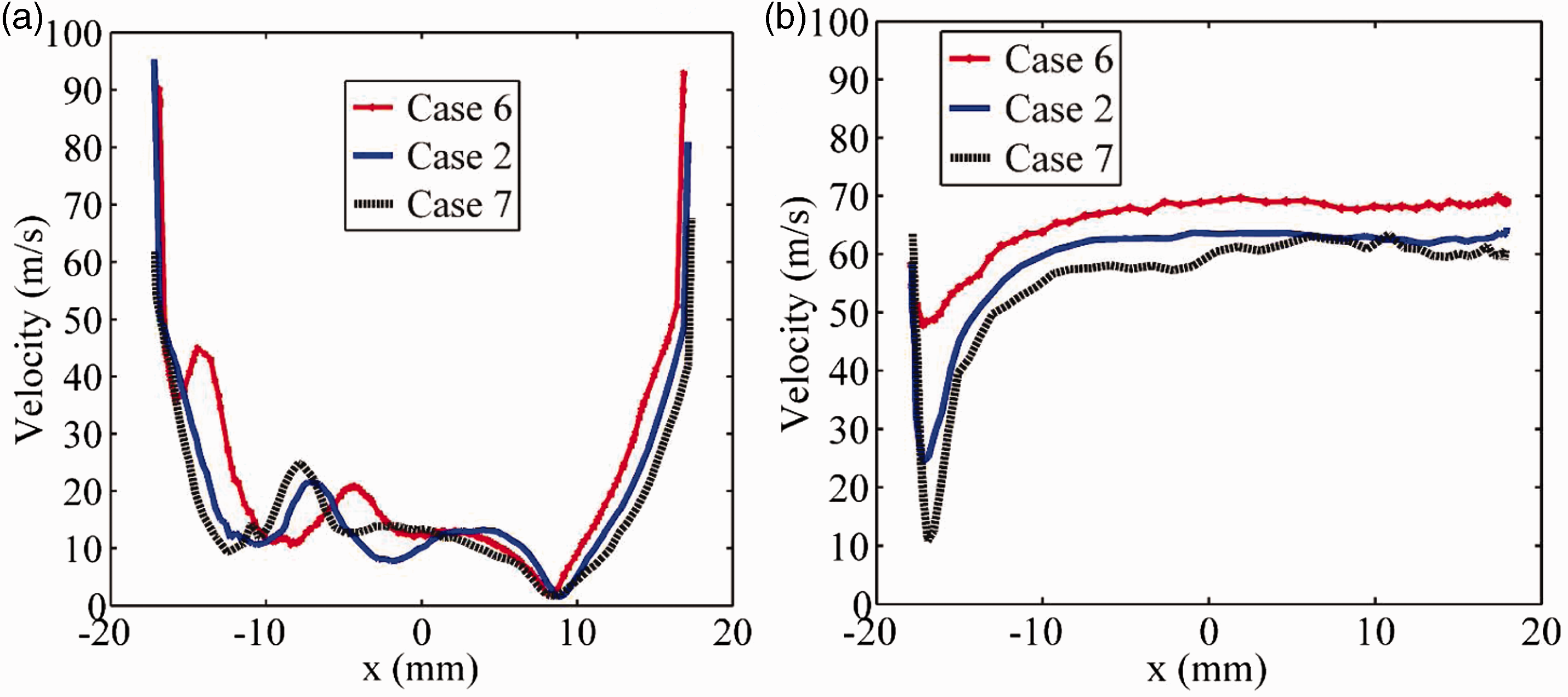
Conclusions
In this paper, we have developed a 3D CFD model to simulate the flow patterns inside the rotor spinning unit, and we compared the simulation results with our experimental data and that reported by other researchers. Furthermore, we analyzed the influence of some design parameters of the rotor spinning unit on both the flow characteristics and the yarn properties.
Velocity difference exists along the transfer channel and at its cross-section, which is beneficial for bending fibers to straighten. The negative pressure inside the rotor seems to be responsible for the flow acceleration along the transfer channel. As the airstream flows into the rotor, it swirls around the rotor wall. The swirling airstream around the rotor groove contributes to fiber converging, while the vortices inside the rotor can be an obstacle to fiber orientation.
We have investigated the effects of rotor speed, rotor diameter and rotor slide wall angle on the flow patterns in the rotor spinning unit. These parameters have a small impact on the flow characteristics in the transfer channel, while obvious variations are observed inside the rotor. Rotor speed affects the flow characteristics in a similar way to rotor diameter. A smaller rotor speed or rotor diameter will produce more vortices around the rotor groove, which will lead to deteriorating fiber configurations and, consequently, lowering yarn properties. However, a rotor speed or rotor diameter that is too large will cause yarn breakage easily due to the excessive centrifugal force, so the rotor speed and rotor diameter must be optimized. The rotor slide wall angle is also one of the most important parameters. As a smaller slide wall angle generates higher velocities in the transfer channel and more stable velocities in the rotor groove, it is preferable to adopt an angle of no more than 76°.
The computational model has provided a useful inside into the flow behavior in the rotor spinning unit, which can relate spinning parameters directly to rotor spinning and thus provide an effective method for optimizing the design of the rotor spinning unit and spinning process.
Footnotes
Funding
This work was supported by the Key Grant Project of Chinese Ministry of Education (Grant 113027A).