
Abstract
Yarn traversing with counter rotating blades is a well-established method of traversing the yarn, employed on several commercial winding machines. This method is mainly suitable for shorter traverse strokes and does not have positive control on yarn during traversing (especially at traverse extremes) as compared to other traversing systems. Moreover, yarn may be subjected to greater abrasion with traversing elements. This may lead to deficiencies such as lack of precision in yarn lay during package build-up that may be reflected in terms of poor package appearance. In this study, the blade profile of the existing yarn traversing mechanism employed on an assembly precision winder has been modified. Three modified blade profiles have been developed with the intention of improving control over yarn during traversing as well as at yarn transfer at traverse extremes from one blade to the other. Packages were built successfully with modified blade profiles. This paper summarizes developmental work of improving profiles of the original design of counter rotating blades to achieve the aforementioned intentions.
Keywords
The yarn traversing mechanism traverses yarn to and fro along the length of the package during winding and this objective can be achieved by a variety of means, counter rotating blades being one of them due to which several machine manufacturers have adopted it. The patent literature describes various yarn traversing mechanisms with counter rotating blades1–9 focusing on different aspects, such as preventing rebounding of yarn at traverse extremes, controlled smooth yarn transfer from one blade to the other, preventing drop in yarn tension at extremes, varying stroke at reversal points to prevent hard edges, etc.
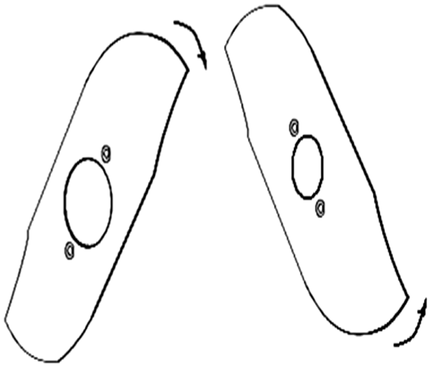
In this research work, an attempt has been made to modify the blade profiles/number of wings in each rotor with an aim to build a better package. The modification in the blade profiles and its practical implementation has been carried out on Peass make assembly precision winding machine (Model PPW-A), shown in Figure 1. The machine permits digital input of the desired winding speed. The path of yarn from the supply package as it passes through tensioning arrangement, yarn feeler/thread stop motion and then to the guide blade along the guide plate to be later on wound on to the delivery package can be clearly seen. The guide plate serves three main objectives: to compensate the tension variations during every traverse, to guide the yarn during its traverse stroke and to relieve the yarn at the traverse extremes. Figure 2 shows the profile of blades supplied by manufacturer, which are referred to as original blades throughout the text.
Winding machine selected for trials. Design of the original blades.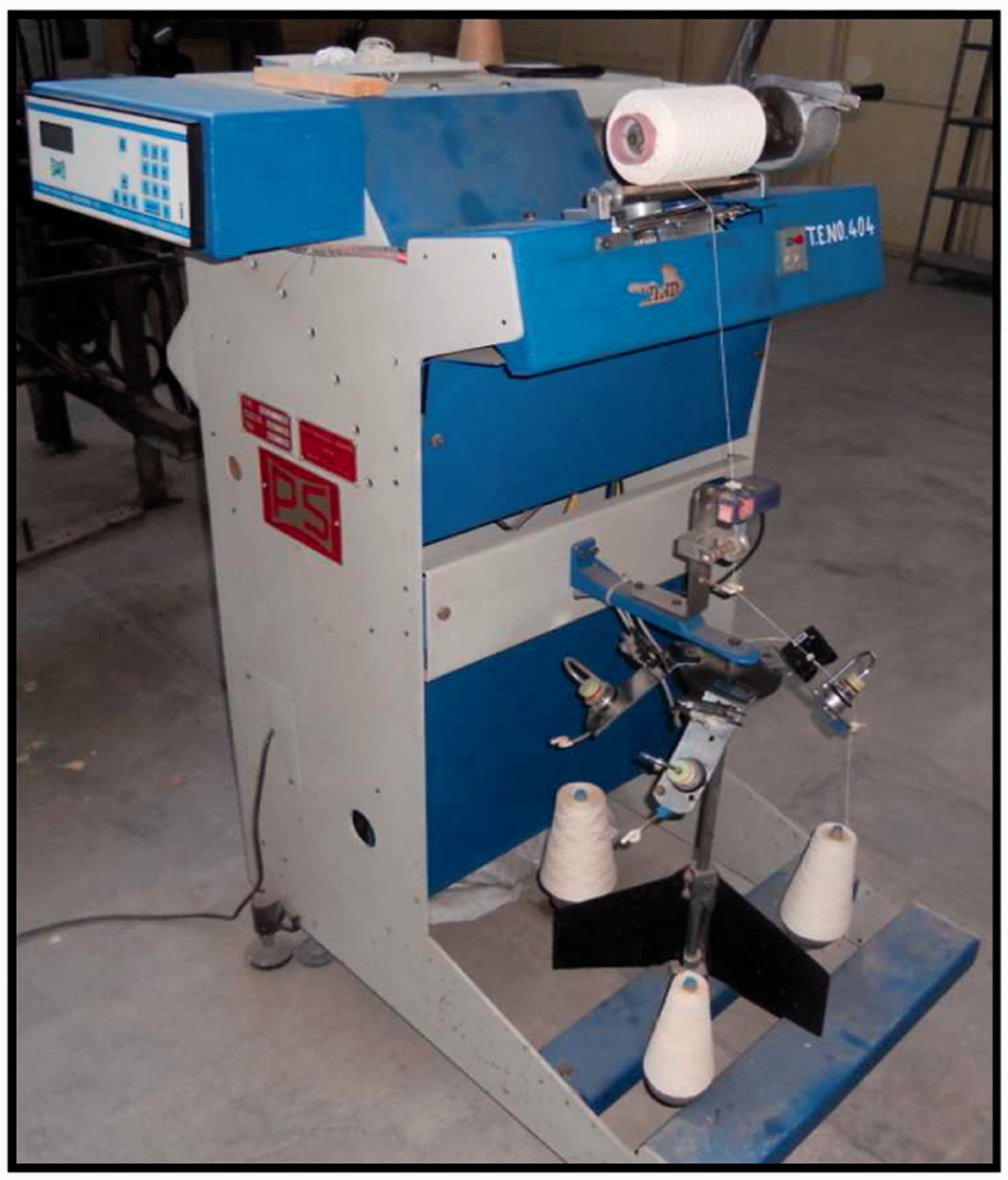
Three different modified traversing blades were developed and winding trials were taken at speeds of 600 and 800 mpm.
Working of original blade
As mentioned earlier there are certain drawbacks related to the design of the original blades due to which flaws in the package built may be observed. The mechanism of yarn traverse with original blades and yarn transfer needs to be understood in order to appreciate scope in its improvement. The mechanism consists of two sets of blades, mounted one above the other, rotating in directions opposite to each with an offset of 5 mm. Consider the yarn to be in contact with a blade moving from left to right, protruding beyond the guide plate and traversing yarn with it. At the right extreme, this blade meets the other blade moving from right to left. At the right extreme, this blade meets the other blade moving from right to left to relieve the yarn and be taken over by the blade moving towards the left, causing yarn reversal. At the left extreme also, exactly similar phenomenon of yarn transfer takes place. It should be noted that yarn should not be against both blades at a time and the taker blade should take control of yarn at the same instant the giver blade relieves it. As the two blades lie in different planes, yarn transfer from one blade to the other becomes a bit critical.
Abrasion of yarn with traversing elements in original blade design
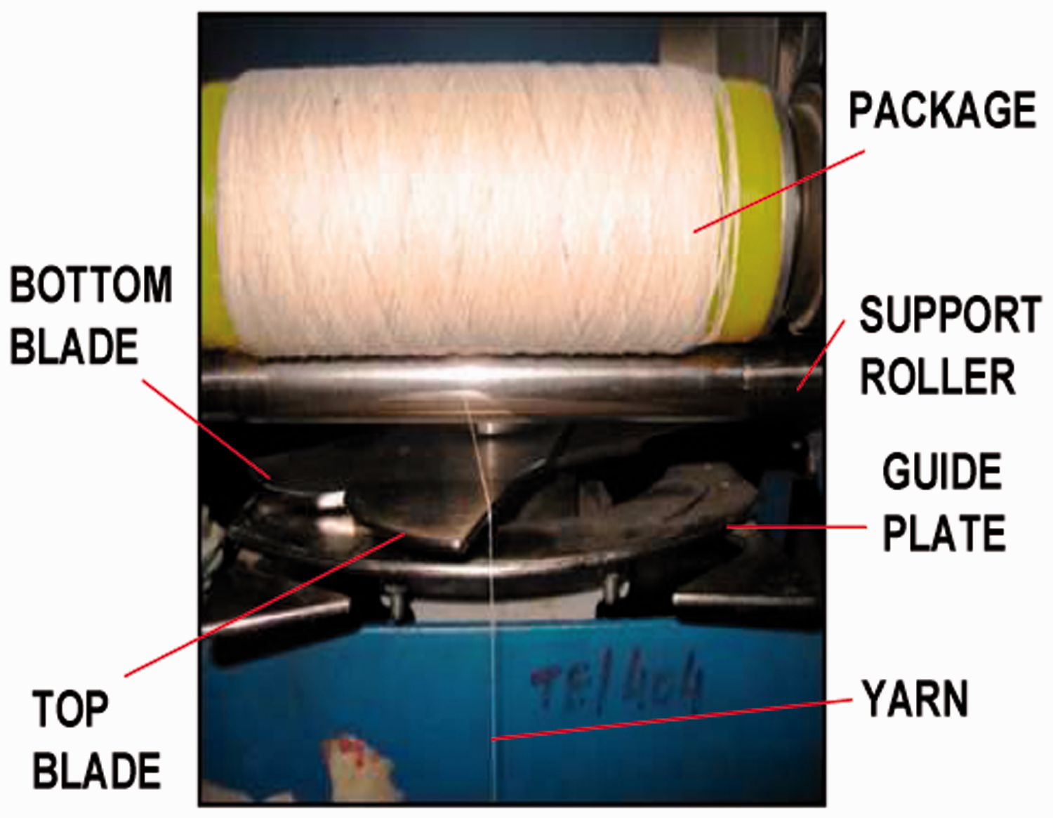
During traversing, yarn is held against the guide blade and the guide plate and would abrade with both these surfaces. When the taker blade takes yarn at the extreme, it has some protrusion beyond the guide plate that keeps on varying until it reaches the other extreme of traverse. The projection of the blade with respect to the guide plate varies during its traverse action due to which yarn has motion along the blade length and that would also cause abrasion of yarn, as clarified in Figure 3. Figure 4 shows a close-up view of the actual traversing system.
Change in position of yarn with reference to the blade profile. B: blade; G: guide plate; S: yarn. Close up of the traversing system.
Lack of control on yarn during yarn transfer in the original blade
Figure 5 shows the situation at yarn transfer from one blade to the other. The blade with its center of rotation towards the right-hand side of the traverse center (giver blade here) is just relieving the yarn as it no longer projects beyond the guide plate. The blade with its center of rotation towards the left-hand side of the traverse center (where the taker blade is) is to take the yarn. When yarn is relieved from the giver blade, the taker blade does not take positive control of yarn immediately. This leaves the possibility of yarn shifting uncontrollably towards the package center momentarily due to yarn tension, which is known as rebounding. It implies that the yarn is not under proper control at extremes that may result in problems related to uniformity in yarn lay during package build-up. A blade traverses yarn from one end to the other during its complete traverse stroke, which is approximately 90° rotation.
Rebounding of yarn at traverse extremes. A: taker blade; B: bottom blade; G: guide plate; S: yarn.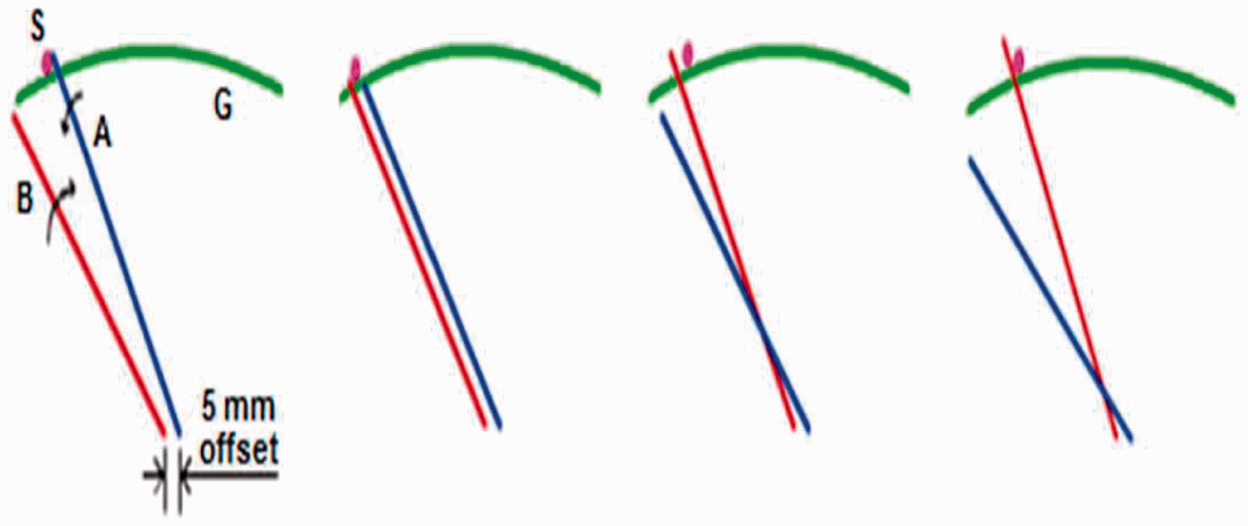
Yarn traverse speed
In grooved cam traverse, the groove angle of the cam remains the same from one end to the other for cylindrical packages in order to achieve a linear traverse (i.e. the traverse speed remains the same from one end to the other). The following discussion is focused to estimate the traverse speed in the case of the original blades. During traversing with original blades (bladed traverse), the radial distance of the yarn contact point with the blade as well as its angle with respect to the package axis changes from one end to the other. The actual dimensions of elements of traverse with original blades were input to AUTOCAD 7.0 and the traverse speed was determined at nine equidistant points along the traverse direction. Figure 6 shows the yarn traverse profile of the bottom blade along with radial distances and the angle drawn at equidistant points along its traverse direction. The nine positions for bottom blade, that move from right to left, are indicated by numbers 1–9 starting from the right, and corresponding radial distances are denoted by R1–R9 for nine equidistant points marked along package axis. The contact points between the yarn, blade and guide plate have been considered for this construction at each position.
Geometry of the bottom blade along with the guide plate, radial distances and angles.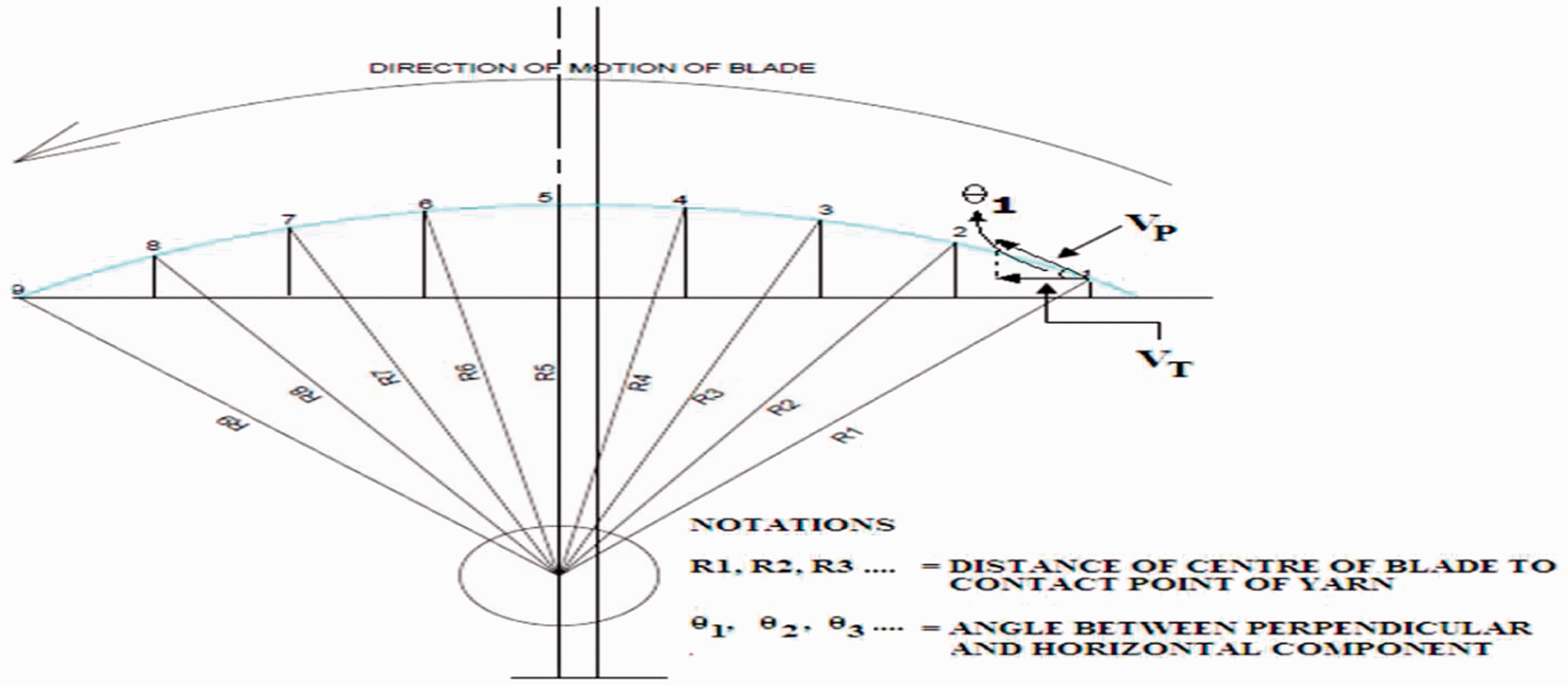
Considering the first point (1), a perpendicular is constructed at this point to the line joining the center of blade rotation and point of traverse on the blade, which gives the direction of instantaneous velocity (VP, i.e. magnitude of instantaneous velocity, is the product of radial distance and blade angular speed; consider angular velocity of the blade as 1 radian per unit time, VP = R) at that point. The magnitude of component of this velocity in the direction parallel to the package axis gives the traverse speed.
A similar construction was carried out for the top blade also.
Velocity calculation for bottom and top blades
The horizontal (x) and vertical distances (y) found from AUTOCAD 7.0 were plotted in MATLAB 9.0 to obtain its polynomial fit at 95% confidence interval and showed an R-square value of 0.8863 for the bottom blade and 0.9893 for the top blade.
The linear model (Poly2) for the bottom and top blades is as follows:
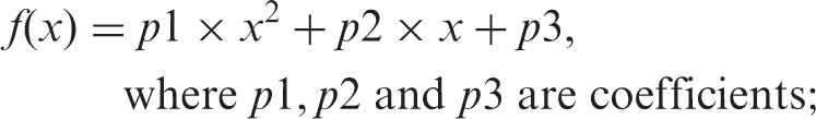
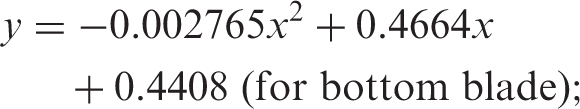

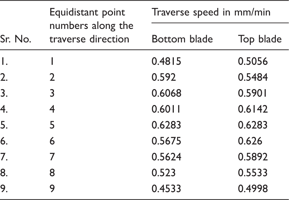
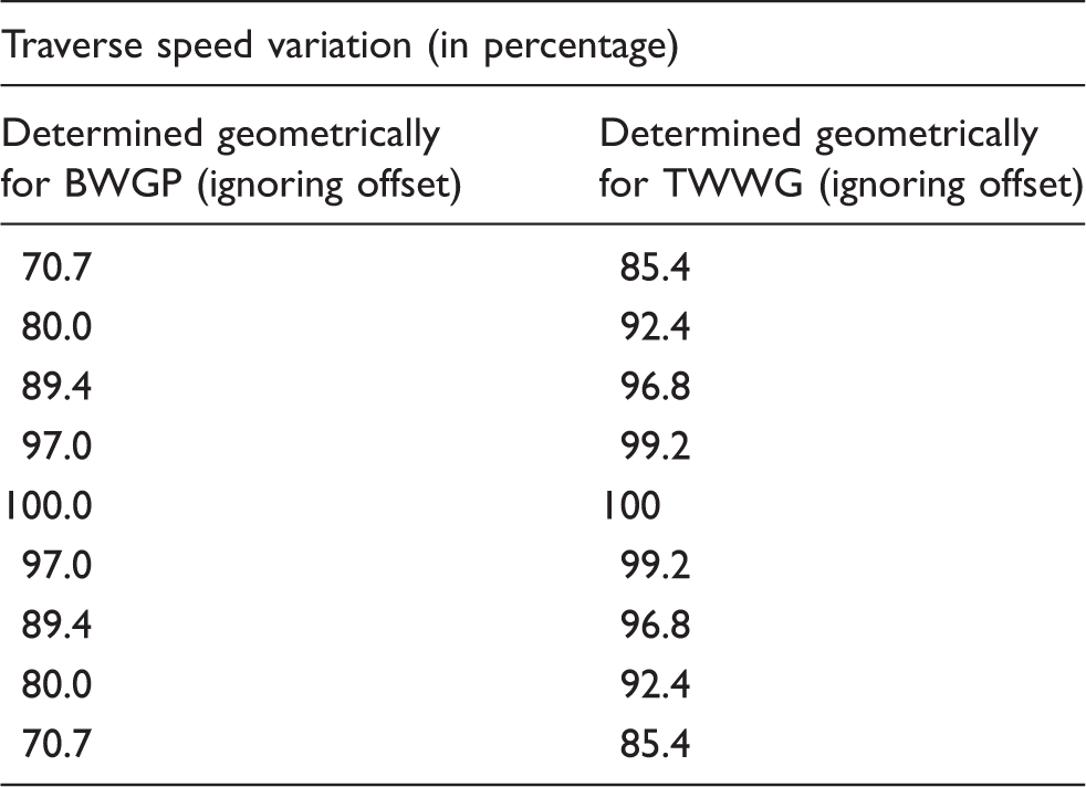
Figure 7 shows the curves created in MATLAB, which have been superimposed (for the benefit of reader) showing the difference in their profiles. Any linear traversing system should give uniform traverse velocity along its traverse direction or else disturbance in the yarn lay may be inevitable. Here two blades are used to propel the yarn along the traverse direction besides being mounted with an offset of 5 mm. This is unlike the usual traversing arrangements, such as a grooved drum/cam that uses only one traversing element, eliminating any possibility of variation in traverse speed. However, from Table 1, it emerges that the original blade design does not maintain uniform traverse speed.
Bottom and top yarn traverse profiles created and superimposed using MATLAB.
From the above discussion, it is clear that there is scope for improvement in the existing design from the point of view of reducing yarn abrasion, preventing yarn rebounding at the traverse extreme and minimizing traverse speed variation during yarn traversing.
Material and methodology
Modification in the original blade profile was carried out from three aspects. Firstly, when the giver blade relieves the yarn at traverse extremes, the taker blade does not take immediate control of yarn that is likely to cause rebounding that should be controlled through modification. Secondly, abrasion of the yarn takes place with blades as well as the guide plate during traversing that should be minimized. Thirdly, yarn position is not confined within the blade profile during traversing that can be modified to confine the position of the yarn within the blade to improve control on the yarn during traversing. Modifications in the blade profile were carried out to seek at least one or more of the above-mentioned shortcomings visualized.
Modified blade with slot and guide plate (BWS)
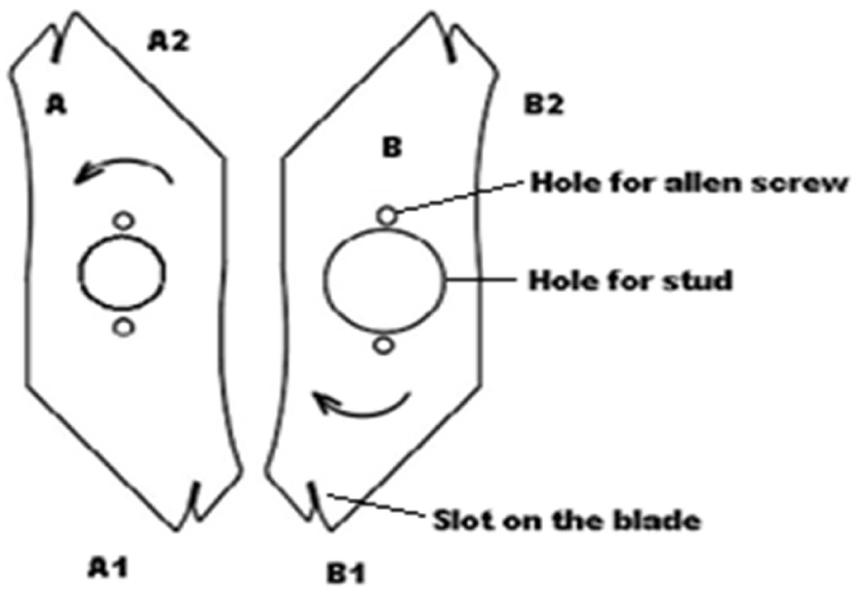
Figure 8 shows the first modification of the blade profile with slot (denoted as BWS in the text). This modified blade carries a slot in which yarn is confined to stay during traversing. The solid line in this figure indicates the profile of a modified blade against that of the original blade indicated by the dotted line. Figure 9 shows a pair of modified blade profiles with a slot. In Figure 10 the slot portion of the top blade is seen moving from left to right, approaching towards the right extreme of traverse where it would relieve the yarn, and the slot portion of the bottom blade moving from right to left would pick up the yarn.
Modified blade profile with the modified blade with a slot. Counter rotating blades with slots. A: top counter rotating blade; B: bottom counter rotating blade; A1 and A2: slots in the top blade; B1 and B2: slots in the bottom blade; S: supply yarn; P: winding package; G: guide plate. Traverse system of the modified blade with a slot (BWS). A: top counter rotating blade; B: bottom counter rotating blade.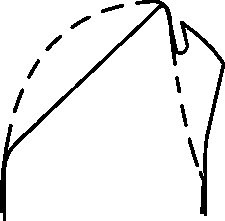

Modified blade with guide profile (BWGP)
The basic design and working of this blade is similar to the one described in the Modified blade with slot and guide plate section. In this modification, instead of a narrow slot, the blade has an in-built yarn guide profile. Figure 11 shows the modified blade profile with a yarn guide (the solid line indicates the profile of the modified blade against that of the original blade, shown by the dotted line). Figure 12 shows the blade profile with guide while figure 13 shows a view of the traverse system.
Modified blade profile with guide. Counter rotating blades with guides. A: top counter rotating blade; B: bottom counter rotating blade; A1 and A2: guides in the top blade; B1 and B2: guides in the bottom blade. Traverse system of the modified blade with guide profile (BWGP). A: top counter rotating blade; B: bottom counter rotating blade; S: supply yarn; P: winding package; G – guide plate.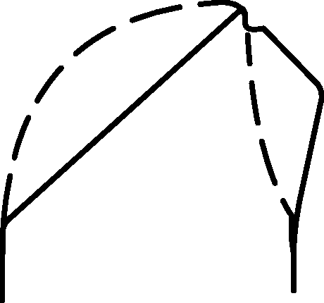


Modification with three wings with guides (TWWG)
The existing traversing system has two wings in each rotor. A system with three wings in each rotor with a modified blade profile that carries a yarn guide at its tip has been developed, as shown in Figure 14. This modification was mainly aimed to minimize traverse speed variations.
Counter rotating blades with three wings. A: top counter rotating blade; B: bottom counter rotating blade.
Improvements in the yarn transfer from one guide to the other at the traverse extreme for all the three modifications
Figures 15(a)–(c), 16(a)–(c) and 17(a)–(c) show the stages of yarn transfer from the giver blade to the taker blade for BWS, BWGP and TWWG, respectively, at their right extreme and the notations represent the same parts in all the figures.
Stages of yarn transfer for the modified blade with slot and guide plate (BWS).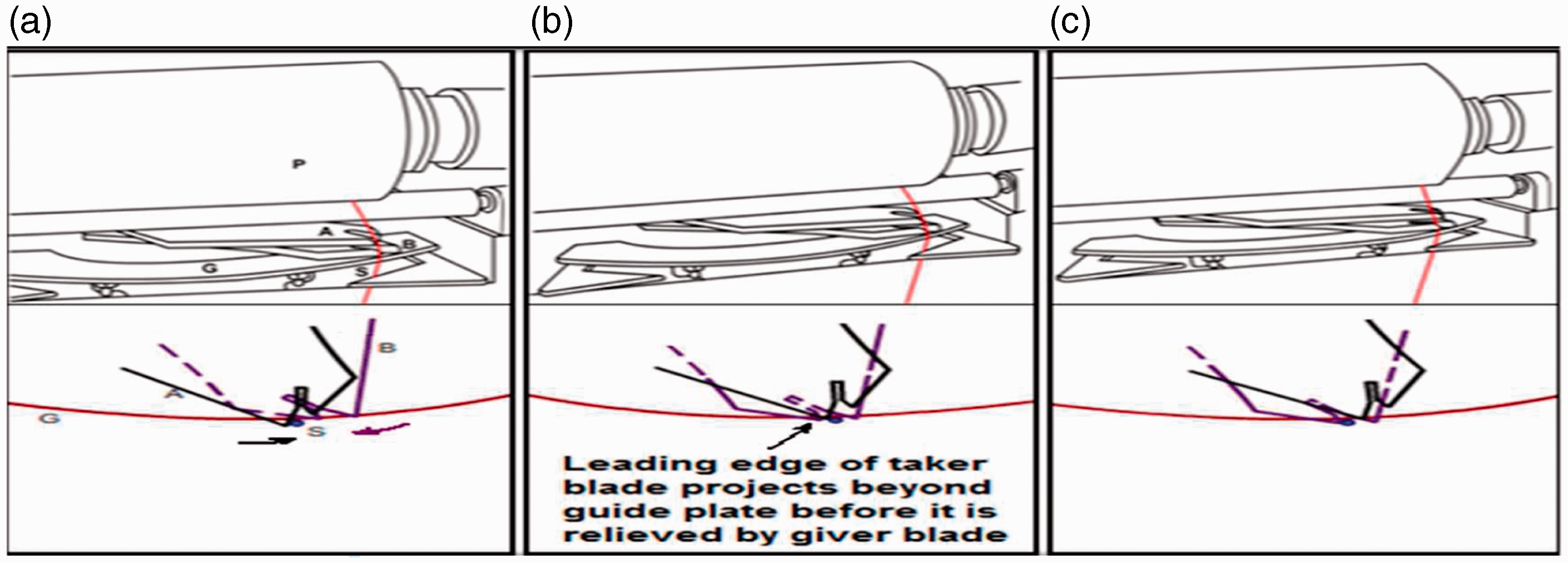
Figure 15(a) shows the yarn under the control of the top/giver blade, while the bottom blade is about to take its transfer position, while Figure 15(b) shows that the top/giver blade is about to relieve the yarn as its protrusion beyond the curved plate has almost diminished and the taker blade is about to take control of the yarn, and Figure 15(c) shows the completion of the transfer. It should be noted that when the giver blade relieves yarn, it tends to shift towards the traverse center. However, just at the time giver blade relieves yarn, the leading portion of the taker blade projects beyond the guide plate that prevents uncontrolled shifting of the yarn towards the center. Subsequently, yarn gets into the slot of the taker blade.
Figure 16(a) shows the yarn under the control of the top/giver blade, when the bottom blade is about to take its transfer position, while Figure 16(b) shows that the top/giver blade is about to relieve the yarn and the taker blade is about to take control of the yarn, and Figure 16(c) shows the completion of the transfer. Here also yarn comes under control of the taker blade when the giver blade relieves it to prevent uncontrolled shifting towards the center.
Stages of yarn transfer for the modified blade with guide profile (BWGP).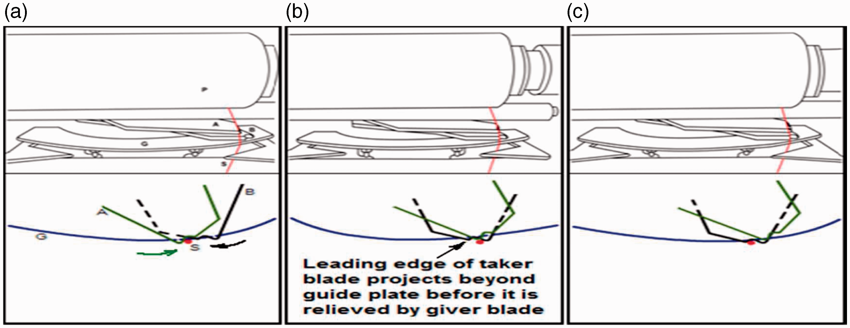
Figure 17(a) shows the yarn under the control of the top/giver blade, while the bottom blade is about to take its transfer position, Figure 17(b) shows that the top/giver blade is about to relieve the yarn and the taker blade is about to take control of the yarn, and Figure 17(c) shows the completion of the transfer. Although the guide plate has been shown in the figures, it needs to be mentioned that relieving of yarn from the giver blade and transfer to the taker blade occurs due to the profile of the guide portion of the blade. However, the guide plate was not removed during winding as it prevented the yarn from entering inside the rotating blades and getting wrapped on to the rotor shaft in the event of yarn break.
Stages of yarn transfer for the modification with three wings with guides (TWWG).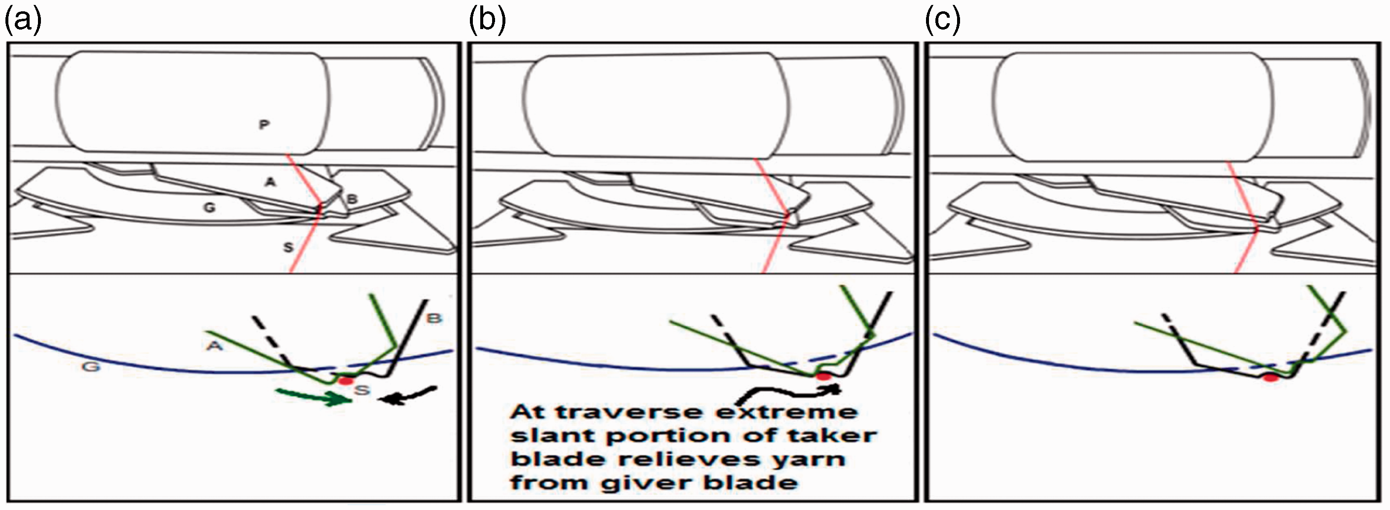
Improvement in the traverse speed
Comparative traverse speed variations

Change in traverse speed in the case of the modified blade with guide profile (BWGP).
Thus, changing the blade design from two wings to three wings reduces traverse speed variation. This design uses guides that ensure proper control over the yarn at extremes, hence avoiding uncontrolled movement of the yarn at traverse ends. Although yarn abrasion with elements of the traversing system was not measured, it can be safely assumed that the abrasion reduces.
Results and discussion
Modified BWS prevented uncontrolled shifting of yarn towards the center at yarn transfer and gave positive control on yarn during traversing. However, rubbing of yarn along the blade profile due to continuous change in its projection beyond the guide plate still persisted. However, changing the projection of the blade beyond the guide plate helps to minimize traverse speed variation. The modification of BWGP also prevents uncontrolled shifting of yarn towards the center at transfer and gives positive control on yarn during traversing. As yarn remains in the guide portion of the blade during traversing, its additional abrasion with the guide plate is prevented, except during yarn transfer at extremes. There is no relative motion between the yarn and blade profile along its length and therefore additional abrasion is avoided. However, traverse speed varies from one end to the other proportional to the cosine of the angle between directions of instantaneous velocity and package axis, as shown in Figure 18. Therefore, traverse speed would be the highest when the radial line joining the center of blade rotation and the yarn guide is at right angles to the package axis, that is, approximately in the middle of the traverse, whereas it would be the least at the extremes. Relation between the blade length and the angle through which it rotates during traversing yarn is close to the following:
2 R sin(Ø/2) = L, where R is the blade length, L is the traverse stroke and Ø is the angular movement of the blade during when it traverses yarn.
For BWS and BWGP, Ø is 90° and for TWWG it is 60°.
The modification of TWWG reduces the traverse stroke by about
Conclusion
It was possible to lay the yarn successfully up to a winding speed of 1000 mpm (the maximum possible speed of the machine mechanically) with all three modified blades. Analysis of traverse speed taking actual measurements on the machine and using AUTOCAD 7.0 showed that traverse speed with the original blades varies. Traverse speeds of the top and bottom original blades at a given location are not identical. Modification in the form of BWS and BWGP can control yarn rebounding at extremes, although no experimental set up was developed to study this. BWGP eliminates yarn contact with the guide plate during traversing, except at extremes during yarn transfer, and is expected to reduce yarn abrasion. As radial distance in BWGP remains constant, it leads to greater traverse speed variation as compared to the original blade. Similarly, TWWG is expected to reduce abrasion of yarn and traverse length is reduced nearly 1/√2times as compared to original blades. Relative variation in traverse speed is the least for TWWG among all blades. The traverse length on the package for TWWG was reduced to 102 mm from 145 mm (for the original blades) at a package diameter of 119 mm. However, if the same traverse length is to be produced, the length of the blade will have to be increased nearly √2 times the length of the original blade.
Footnotes
Funding
This research received no specific grant from any funding agency in the public, commercial or not-for-profit sectors