
Abstract
Frequency selective surfaces (FSSs) based on textile or textile composite materials are increasingly becoming popular due to their textile nature of high flexibility, softness, low-cost, easy fabrication, and other textile characteristics compared to the traditional metal FSS, especially the two-dimensional FSS fabrics. In this study, a three-dimensional (3D) fabric periodic structure with conductive textile fabricated vertically on the common textile substrate, forming a U-shaped array, is proposed. An experimental validation has been conducted to verify whether the 3D frequency selective structure fabric has good frequency response characteristics and great design ability. The model samples of 3D periodic structure based on velvet fabric with different structure or material parameters were fabricated by hand. Through testing and analysis of transmission and reflection coefficients at 2–18 GHz using the shielding chamber method, the results show that the velvet height of the fabric model periodic structure has an obvious effect on the resonant frequency. With an increase in velvet height, the resonant peak will move towards lower frequency. With an increase of vertical velvet spacing, the resonant frequency will also move towards lower frequency. Velvet material has a slight influence on the frequency response characteristics. The frequency response characteristics of this structure are stable under different incident angles. The 3D periodic structure offers more design freedom and possibilities. Significant effects of wave absorption or selective filtering by the periodic structure can be achieved by regulating the structural parameters and material parameters together.
Keywords
The periodic structure, which is a spatial filter with total transmission or reflection characteristics at a certain frequency, mainly finds important applications in microwave ovens, mobile phones, satellite antennas, radar systems, sensors, etc. 1 Conventional studies have mostly focused on a one-dimensional/two-dimensional (2D) periodic structure, which is commonly named a frequency selective surface (FSS). 2 An FSS is a surface that has a periodic assembly of thin conducting sheets or metallic patches in a flat, perfectly conducting sheet. 3 FSS stealth technology can effectively improve battle effectiveness. Therefore, periodic structures play a more and more critical role in modern science and technology. Many scholars have researched the frequency response characteristics, analysis methods, and design methodology of FSSs.4–15 The frequency response characteristics of an FSS mainly depend on the resonant unit shape, arrangement mode of the unit, and the electrical properties of the surrounding medium. 4 They are also influenced by the polarization and incident angle of the incident electromagnetic wave.8–10 There are quite mature methods at present, such as the approximate analysis, model analysis, and finite-difference time-domain analysis methods. Design and optimization of FSSs have also become increasingly mature.11–15.These methods will benefit the better development of FSSs.
Conventional FSSs are made of metal materials and medium materials such as plastics. They are rigid and unyielding, which makes them restricted to some specific applications and design. Therefore, FSSs based on textiles have attracted increased attention. Cavalcante et al. investigated the characteristics of FSSs on textile substrates because of their properties of high flexibility, low weight, low cost, high strength, and ease of fabrication compared with traditional metal FSS. 16 Tennant et al. investigated use of the textile manufacturing knitting process to fabricate conducting textile structures.17,18 Chauraya et al. studied low-loss textile FSS structures for wearable applications. 19 Seager et al. proposed two examples of fabric-based FSSs which were produced by using screen printing and weaving. 20 Lee et al. proposed a frequency selective fabric composite consisting of carbon fiber and low-loss dielectric substrate, 21 which had better transmission performance than the metal FSS. Lee et al. were the first to carry out research on the electromagnetic properties of carbon fiber and dielectric fiber blended fabric composites. 22
However, with reference to the three-dimensional (3D) and finite structures used in practical applications, it is difficult for 2D FSSs to meet the specific requirements. In some cases, 2D FSSs can hardly satisfy requirements in terms of the mechanical properties of structures; therefore, research on 3D structures is necessary. The increase in the dimensionality may help to solve some current problems. For the absorbing properties, the properties of 2D FSS depend largely on metal and medium material, and it is difficult to achieve better absorbing properties basing on current materials. In contrast, the absorbing properties of 3D periodic structures will not only depend on the materials, but also on the variation of the shape and complex 3D structure. There have also been few explorations concerning 3D periodic structures. Lee and Hong confirmed that the proposed 3D FSS can provide better frequency stability for different incidence angles and polarizations as well as miniaturized unit cell size. 23 Azemi et al. proposed a new type of frequency selective structure which was a modification of a 3D FSS consisting of square cross section cylinder unit elements. 24 Li and Shen described a new class of 3D band pass FSSs based on an array of shielded micro-strip lines. 25 Pelletti et al. described a 3D FSS element that generates a flat band pass response over a wide band, 26 as well as controllable low-pass angular response. Wu et al. simulated and analyzed the effect of polarization, incident angle, and medium load method on the frequency response characteristics of a 3D periodic structure by using simulation software. 27 However, for 3D textile FSSs, the situation is more complex and further, more detailed studies are necessary.
Base on 3D fabric weaving technology, Xiao et al. put forward ideas concerning 3D FSS fabrics and their probable configuration methods, 28 such as velvet fabrics and looped pile fabrics made of yarns with metal properties. They also pointed out the advantages and applications of these fabrics. The 3D weaving technology and advanced textile manufacturing techniques, such as computerized flat-bed knitting, can also be used to create a variety of 3D and conformal structures to certain geometries. 29 The manual model samples described in this paper are supported by the tufted weaving technology. At present, the tufted weaving technology is of high accuracy. According to a preliminary study, it was confirmed that it is feasible to design a 3D fabric periodic structure using this technology. Different unit designs with varied size were manufactured through the configuration of metallic yarn and ordinary yarn.
With the support of such technology, a 3D velvet fabric periodic structure prototype based on velvet fabric was manufactured by hand. The factors influencing its frequency response properties, such as velvet height, velvet spacing, the velvet material, and the incident angle, were researched in this work. It can be concluded that, according to the elaborate design of such velvet fabric, a 3D FSS with excellent performance can be achieved. Significant effects of wave absorption or selective filtering by the periodic structure can be achieved by regulating the structural parameters and material parameters together.
Experimental details
Materials
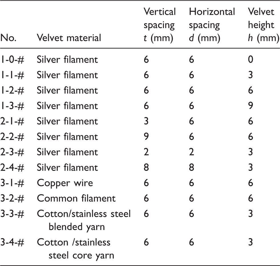
Conductive fibers or yarns, such as silver filaments, were used to fabricate the velvet fabric periodic structure model samples. Silver filaments, which have nylon as their core yarn, not only have good conductivity, but also excellent mechanical properties and durability.
The parameters of applied materials

Specimen fabrication
What was conducted in this work is an exploratory physics experiments. The 3D velvet fabric periodic structure prototype based on velvet fabric (shown in Figure 1) was manufactured by hand. Figure 1(c) shows the tufting carpet sample machine. The vertical needle gauge had different grades of 3 mm, 4 mm, and 5 mm and a stitch length range from 2 mm to 8 mm, while the pile height varied from 1 mm to 40 mm.
Velvet fabric structure model: (a) schematic diagram; (b) Photograph of front view of sample. (c) Tufted carpet loom.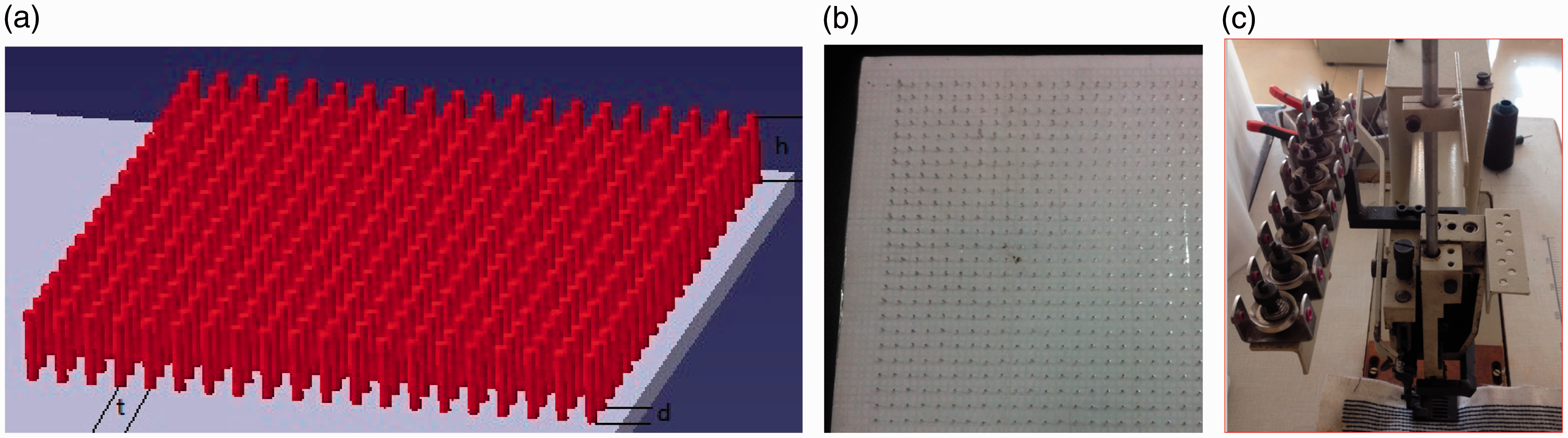
The substrate in this fabric structure model was common paper cardboard with a relative dielectric constant of ɛ = 2.5, ρ → ∞, which corresponds to the plain woven substrate in the real velvet fabric. The manufacturing process of the model includes two steps. Firstly, the substrate cardboards with dimensions of 18 cm × 18 cm × 0.01 cm were made.
The parameters of the samples
Measurement of transmission coefficient and reflection coefficient of the specimen
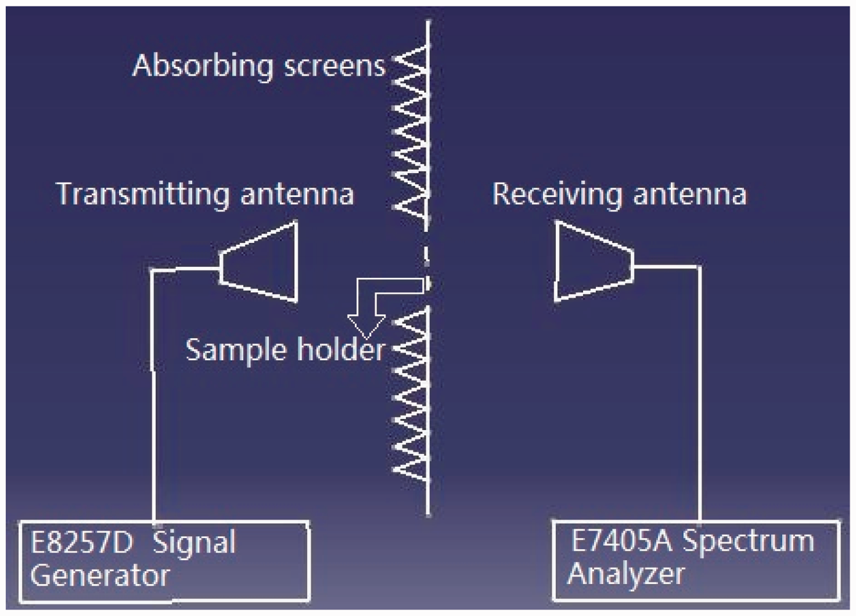
As shown in Figure 2, the testing system for transmission coefficient included an Agilent E8257D signal generator (250 KHz–40 GHz), an E7405AEMC spectrum analyzer (100 Hz–26.5 GHz), horn antenna (1 GHz–18 GHz), and absorbing screen. Transmitting and receiving antennas were connected to the signal generator and spectrum analyzer, respectively. The absorbing screen was between the two antennas. Transmitting and receiving antennas were parallel with the center position of the specimen holder. The calculation formula for the S21 transmission coefficient (unit: dB) is, after simplification, as follows:
The testing system for shielding effectiveness.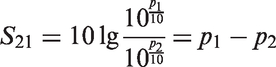
The reflection coefficients R (unit: dB), which were measured using the Arch test method, are found via the formula:
The testing system for reflection coefficient.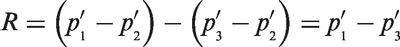
In order to study the frequency response characteristics of the velvet fabric periodic structure, the transmission and reflection coefficients of these specimen were measured in the range 1–18 GHz for different incident angles in the TE (transverse electric: the electric field component only in the plane perpendicular to the propagation direction) or TM (transverse magnetic: the magnetic field component only in the plane perpendicular to the propagation direction) plane. In addition, results were obtained by minimizing the environment value to avoid the influence of some accidental factors which may lead to attenuation between the reception signal and transmission signal.
Results and discussion
Effect of velvet height on frequency response characteristics
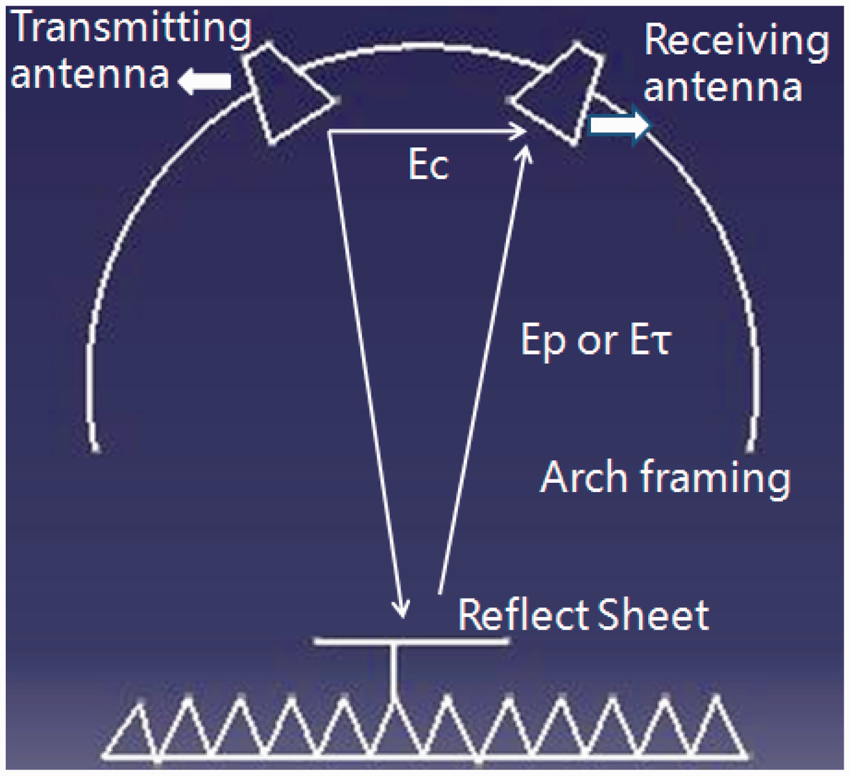
Under the same conditions, samples with different velvet heights of 0 mm, 3 mm, 6 mm, and 9 mm were tested for their electromagnetic wave transmission and reflection coefficients. The results are shown in Figures 4 and 5. From Figure 4, it can be seen that when the height is 0 mm, waves are all transmitted without selectivity. Figure 4 also shows that with the increase of velvet height, the resonant frequency will move rapidly towards lower frequency and the bandwidth will become narrower. The reason may be the lower the frequency, the longer the wavelength, then the easier the resonant behavior between wave and velvet. When h = 0 mm, which means the sample is 2D FSS, the transmission coefficient is close to zero at 1–18 GHz, the resonant frequency of the sample may occur in about 25 GHz. According to experience, the unit length of a dipole in a 2D FSS is approximatively equal to half a wavelength at a resonant frequency. However, an analogy cannot be drawn between the unit size of a 3D structure and electromagnetic wavelength. There are also a lot of correlative matrix effects which cannot be ignored, such as the height of the units. In a word, the velvet height has an obvious effect on resonant frequency, which is of great significance for guiding subsequent research on 3D fabric periodic structures. For the reflection coefficient curves in Figure 5, in the band corresponding to the resonant frequency in the transmission coefficient curves, the reflection coefficient is close to zero, indicating that the transmission of the wave is small and that the structure has good reflective properties.
Transmission coefficient results for samples with different velvet height h. Reflection coefficient results for samples with different velvet height.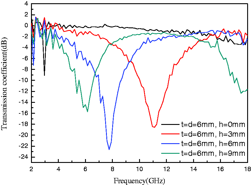
Effect of cell size on frequency response characteristics
When the longitudinal spacing d and the height h of the velvet were equal to 6 mm, a group samples with different velvet spacings of t = 3 mm, 6 mm, and 9 mm were made. When the height h was equal to 3 mm, a set of specimens with t = d = 2 mm, 6 mm, and 8 mm were made. By testing the electromagnetic wave transmission and reflection coefficients of these samples, the results shown in Figures 6 and 7 were obtained.
Transmission coefficient results for samples with different vertical velvet spacing t. Reflection coefficient results for samples with different velvet spacing t.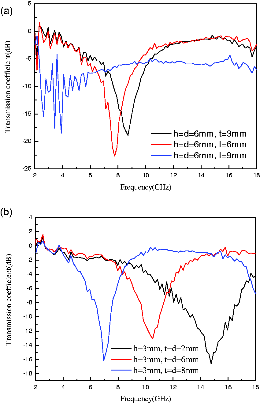
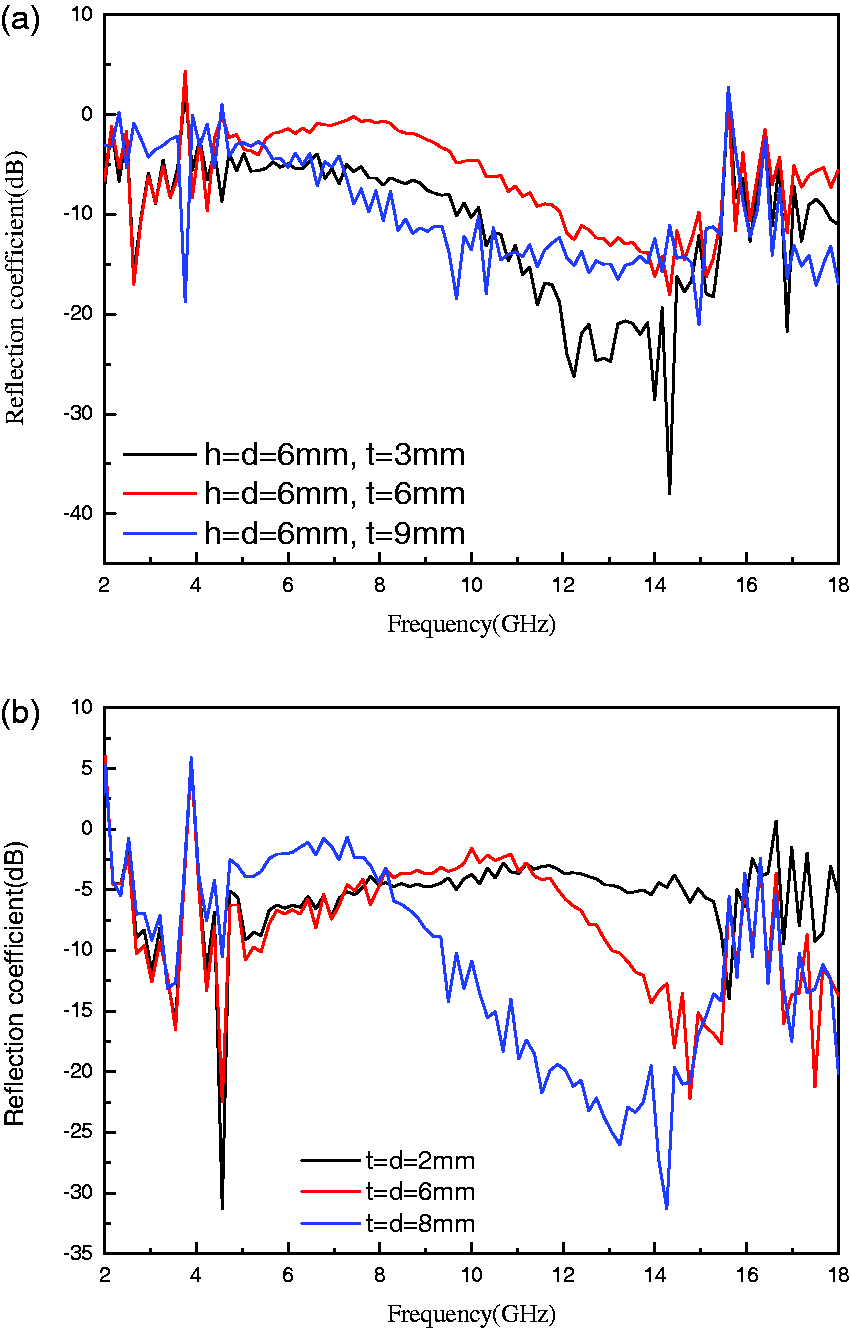
As can be seen in Figure 6(a), with the increase of vertical velvet spacing t, the resonant frequency will move towards lower frequency slowly and the bandwidth will taper, showing that the vertical velvet spacing mainly influences the bandwidth, while slightly influencing the resonant frequency. However, as shown in Figure 6(b), with the increase of the two-way distance, namely, unit size and spacing, the resonant frequency will be greatly moved towards the lower frequency, and the bandwidth will also taper. The change of bandwidth is related to the equivalent capacitance and inductance of the structure surface, and the change of cell spacing can affect the equivalent capacitance. The change of the resonant frequency is related to the electric current of the unit, and the change of the length d of the unit can affect the electric current of the unit. Therefore, the unit spacing t mainly influences the bandwidth and unit length d mainly affects the resonant frequency. For the reflection coefficient in Figure 7(a) and (b), in the band corresponding to the resonant frequency in the transmission coefficient curves, the reflection coefficient of samples 1-1-#, 1-2-#, 2-3-#, and 2-4-# is close to zero, indicating that they have good reflective properties at their resonant frequency, namely, the periodic structures have good band-stop performance. Though it appears that the reflection coefficient of samples 2-1-# and 2-2-# is not very good, just through adjusting the reflection and transmission coefficients, the performance may meet actual demand.
Effect of velvet materials on frequency response characteristics
When d = t = h = 6 mm, three samples were manufactured with different velvet materials of silver filament, copper wire, and common nylon filament. When d = t = 6 mm, h = 3 mm, three samples using silver filament, cotton/stainless steel blended yarn, and cotton/stainless steel core yarn were made. By testing the electromagnetic wave transmission and reflection coefficients of these samples, the results shown in Figures 8 and 9 were obtained.
Transmission coefficient results for samples with different velvet materials. Reflection coefficient results for samples with different velvet materials.
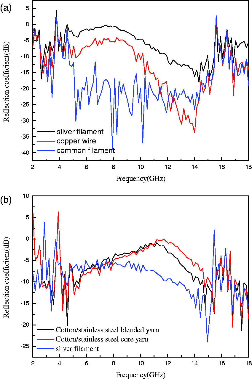
Obviously, as can be seen in Figure 8(a), the transmission coefficient of the ordinary nylon filament, which is a non-conductive textile material, is almost 0. This indicates that non-conductive materials have almost no effect on the spread of an electromagnetic wave, as also indicated by the reflection coefficient in Figure 9(a) which is as small as environment values. As shown in Figure 8(b), the resonant peak of copper wire is sharper and the bandwidth is smaller than that of silver filament due to the better conductivity of the former. In Figure 9(b), both the bandwidth and resonant frequency peak value of silver filament sample are larger than that of cotton/stainless steel samples. Because the conductivity of the former is better than that of the latter, and the latter has a certain magnetic permeability, which will influence the frequency response characteristics. That’s to say, velvet materials also have an influence on transmission characteristics, but a small influence on resonant frequency.
Effect of the bottom connectivity on frequency response characteristics
The bottom connection parts of the conductive velvet were cut to form an independent columnar structure, and their transmission coefficient was tested and compared with that of the prototypes before cutting. We used three samples to carry out the contrast of bottom connectivity and unconnectivity, the test results for which are shown in Figure 10(a) to (c). These three figures show that when the bottoms of the prototypes were unconnected, the frequency response will disappear. This means that the bottom connectivity has a critical effect on the frequency response characteristics. It has been verified before that the velvet height has an obvious effect on response characteristics. Therefore, it is the combined effects of height and connectivity of velvet that exert an influence on the frequency response characteristics.
Transmission coefficient of samples before and after cutting.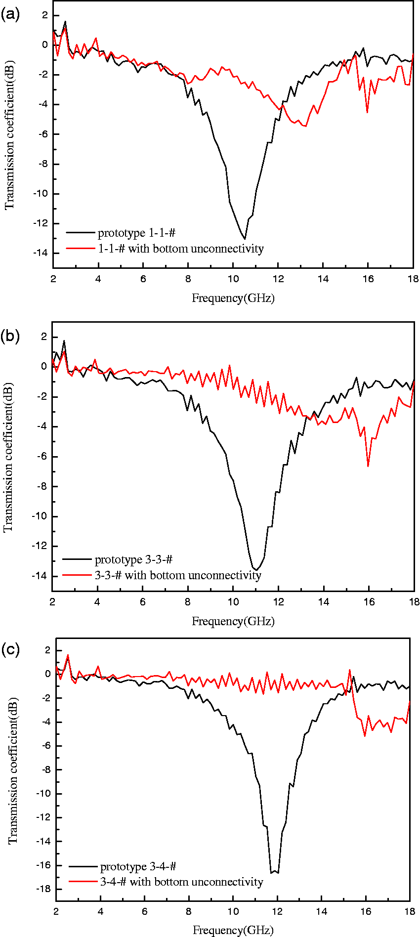
Effect of incidence angle on frequency response characteristics
Rotating the sample 1-2-# with different angles, and testing the reflection coefficient under different incident angles, the results shown in Figure 11 were obtained.
Reflection coefficient results for samples under different incidence angles.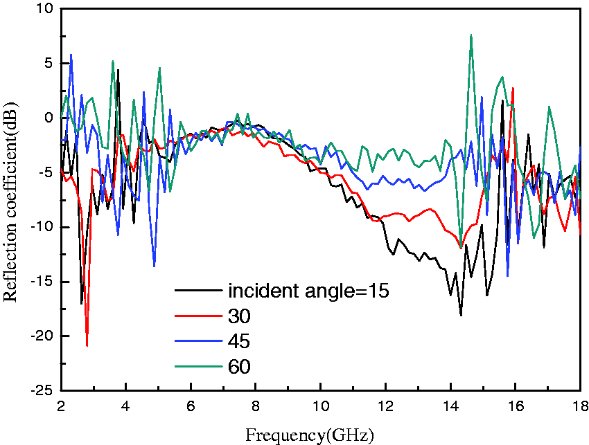
As shown in Figure 11, at 4–14 GHz, especially at the resonance frequency of the prototype, which is about 8 GHz, the reflection coefficient is almost zero. This means that there are excellent reflection properties at this resonance frequency. In addition, with the change in incident angle, the resonant frequency and reflection performance have no fluctuation. This indicates that this structure may have certain angle stability. More details will also be verified in a later experiment.
Conclusion
Through analysis of the above data, it can be seen that velvet height, velvet spacing, and velvet material each have an obvious influence on the frequency response of the 3D FSS sample. With the increase of velvet height h, the resonant peak will move towards lower frequency. With the increase in vertical velvet spacing, the resonant frequency will also move towards lower frequency. Velvet material has a slight influence on the frequency response characteristics, and the frequency response characteristics of this structure are stable under different incident angles. Bandwidth is mainly influenced by cell spacing; with an increase of cell spacing, the bandwidth will be narrower. As shown in Figures 8 to 10, the velvet connectivity in the back is critical to frequency response characteristics. As this paper only reports an exploratory experiment, more detailed research is necessary.
Textile materials offer advantages such as light weight, high-strength-to-weight ratios, flexibility, low cost, and easy access. Functional conducting textiles may also be integrated into composite structures to produce better materials. What’s more, advanced technology for 3D weaving and material production, together with the fact that they are more conducive to multiple reflection and absorption of electromagnetic waves than 2D FSSs, should enable 3D textile FSSs to have great development prospects and economic value.
Therefore, 3D periodic structure FSS fabrics will offer a great direction for FSS research. However, because of the complexity of the real situation, further exploration and a large amount of work in subsequent investigations will be necessary. The rapid development of science and technology in society, and the emergence of all kinds of precision weapons and electronic warfare tools, will make the research of periodic structures to be more greatly appreciated.
Footnotes
Funding
This research is supported by Natural Science Foundation of China No.51403232 and Army program No.BX113C004.
Conflict of interest
The authors declared no potential conflicts of interest with respect to the research, authorship, and/or publication of this article.