
Abstract
A mathematical model based on the principles of conductive heat transfer is presented to predict the thermal resistance of cut pile carpet. The cut pile carpet assembly is considered as a network of thermal resistances of the tuft yarns, trapped air, and the primary backing fabric. A straightforward calculation of the thermal resistance was not possible as the data for thermal conductivity of the tuft yarns along their axes was not known. Therefore, the calculation of thermal conductivity in the direction of the yarn axis was based on the construction of surface pile and on the measured thermal resistance of carpet for a set of samples. Theoretical thermal resistances of another set of cut pile carpets were calculated by applying the developed thermal model. The results show that the simple network model is robust and gives reasonable values by using the carpet construction parameters. The model can be used for engineering of cut pile carpets to provide a desired level of thermal insulation.
People in industrialized countries generally spend more than 90% of their life inside buildings. Leech et al. found in a time–activity survey that the subjects on average spent only 2–4% in the outdoors during wintertime. 1 Therefore the indoor environment comfort is extremely related to the occupants’ health, satisfaction, and working efficiency. One of the four basic factors to determine the indoor environment comfort condition is thermal comfort. 2 Achieving optimal heat and moisture levels within a room is a key contributor to thermal comfort. Conversely, poor heating and/or inadequate insulation in homes has been shown to be associated with an increase in deaths and also impacts significantly on respiratory illnesses. 3 Cui et al. found out that under the warm or cold discomfort environment the learning rate was slow down and the optimum temperature range for performance was between 22℃ and 26℃. 4 One of the prominent functions served by carpets is to provide warmth and comfort. The Carpet Institute of Australia has shown that the thermal resistance (R) values of carpet and fiber glass insulation with the same thickness 1 cm are close to each other. 5 In addition, carpet has significantly higher R value than concrete and plywood that are popular hard floor covering materials. Therefore, carpet can help to reduce heat loss through the floor when an outdoor temperature is lower than indoor temperature. This may lead to a considerable amount of savings in energy for indoor heating. Although the mechanical behavior of carpets has been reported by many researchers,6–10 the thermal insulation properties of the carpets are rarely studied. The present work is concerned with the heat transfer through cut pile carpets and its basic objective was to develop the mathematical model involving construction parameters to predict thermal resistance of the cut pile carpets. Such model may be useful for manufacturers and product designers to produce carpets having a desired level of thermal insulation property. This may also help interior designers to select the right kind of carpets for providing a required level of indoor thermal environment.
Theoretical part
Heat flow through textile material
The process of heat transfer through textile material by conduction is mathematically expressed by Fourier’s equation as

Thermal resistance of textile material
Thermal resistance characterizes a material’s ability to prevent heat passage through it. It is a function of the thickness and thermal conductivity of a material which is influenced by material structure and composition. In case of fabrics or garments under compression, thickness is further reduced and thermal resistance becomes lower due to the relationship

Carpet construction
A hand tufted carpet is created by punching yarns through the primary backing fabric which is stretched on the frame or loom. The tufting process employs the tufting gun. After tufting, a secondary backing fabric is laminated and bonded by adhesive for greater strength and dimensional stability. Thus, the tufted carpet generally consists of four components: surface pile, which may be cut, loop or combination of cut and loop; primary backing fabric; adhesive compound, which can be natural rubber latex or SBR (styrene-butadiene rubber latex); and secondary backing fabric.
19
The cut pile tufted carpet construction is shown in Figure 1.
Schematic of cut pile tufted carpet construction: (1) surface pile, (2) primary backing fabric, (3) adhesive, and (4) secondary backing fabric.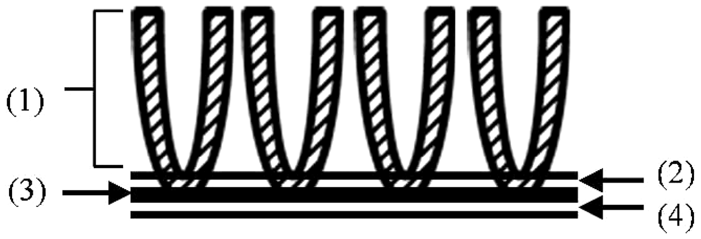
Modeling the carpet assembly
Since carpets have a composite structure, it is necessary to consider thermal properties of both surface pile and backing parts if we are to characterize the state of thermal properties of entire cut carpet. Due to the temperature difference between the contact area of feet and the carpet surface, heat will tend to move from this carpet surface through the pile, the trapped air and the fabric backing to the floor. In this section we describe the structural model used to obtain thermal resistance and thermal conductivity of the carpet yarn in the same direction of yarn axis of cut pile carpet. It was assumed that the surface pile assembly was cuboid consisting of cylindrical yarn parallel to each other and trapped air which presents another insulating material. The structure model of cut pile carpet is shown in Figure 2(a). The actual area of yarn and air within unit area of the surface pile can be calculated in term of geometry of the yarn as follows
Modeling of thermal resistance of cut pile carpet: (a) the structural model of cut pile carpet; (b) the network of equivalent electrical circuit model for thermal resistance.


Calculation thermal resistance of cut pile carpet
In order to develop the theoretical model for predicting thermal resistance of the cut pile carpet, the following assumptions were made:
the conductive heat transfer takes place through the carpet yarn in the same direction of the yarn axis and trapped air; the effects of convection and radiation can be neglected; primary backing fabric is represented by the thermal resistance of the fabric and distortions in fabric structure due to tufting are neglected; the secondary backing and adhesive are not considered in this study.
To derive a relationship for the carpet structure and its thermal resistance, the real situation is replaced with a network of resistances. The network is shown in Figure 2(b), where thermal resistance of cut pile carpet is assumed to be represented by a series circuit of surface pile resistance and primary backing resistance. The relationship between thermal resistance and thermal conductivity is shown in the following expression, where RY, RA, and RB are thermal resistance of yarn, air, and primary backing fabric, respectively, RYA is thermal resistance of surface pile, and RC is thermal resistance of carpet. Then the basic equation of thermal resistance of carpet is given by

For lucidity, the steps given for the derivation are shown as follows:

Equation (6) can be substituted in equation (5). Then, the thermal resistance of a cut pile carpet is given by

Based on equation (2), RA is given by the following equation in which the thermal conductivity of air, λA, is 0.025 W/(m K):

From equation (7), the thermal resistance of yarn can be calculated as follows:

The thermal conductivity of the yarn can be calculated as

Experimental part
Sample arrangement
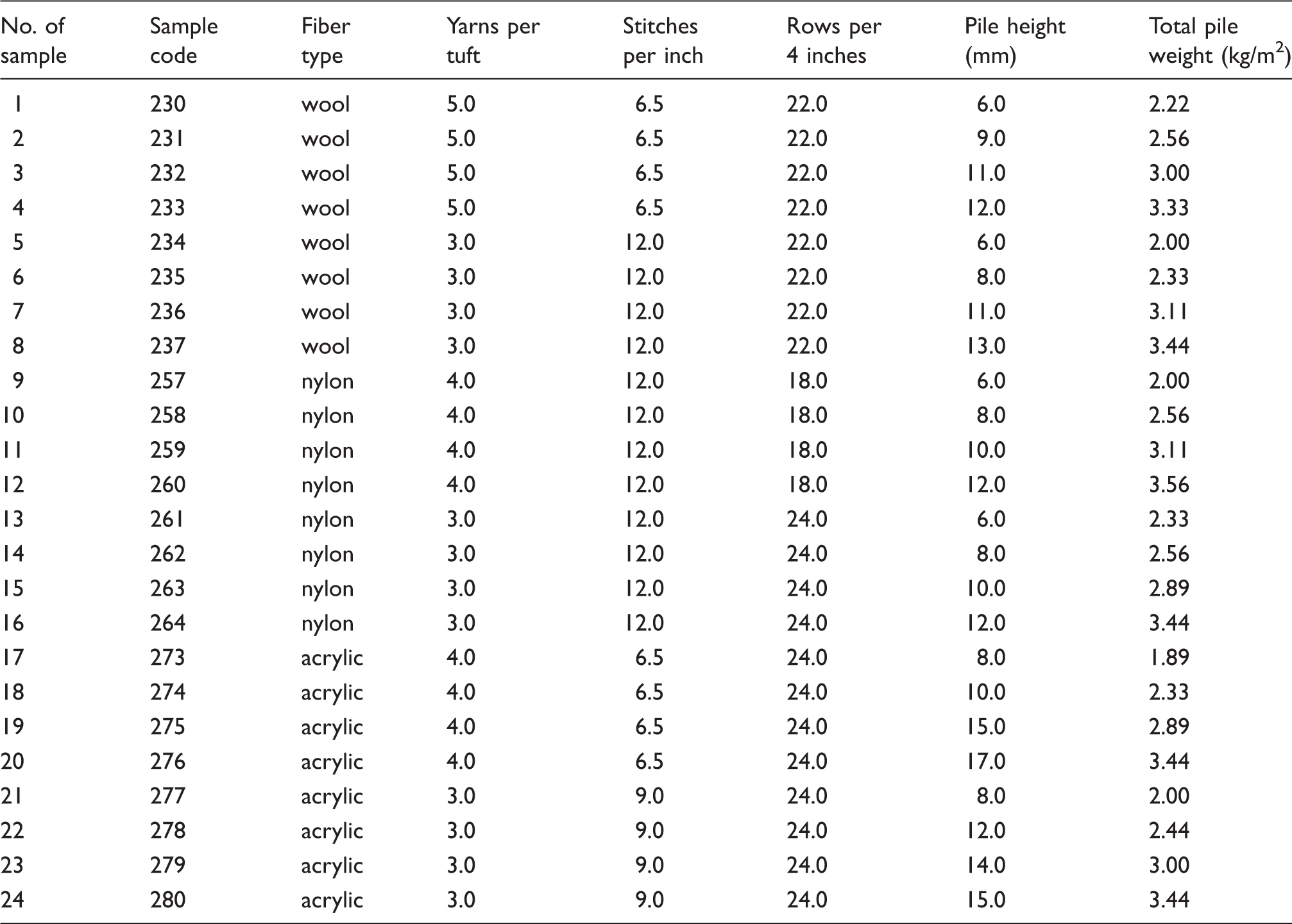
Specification of cut pile hand tufted carpet samples
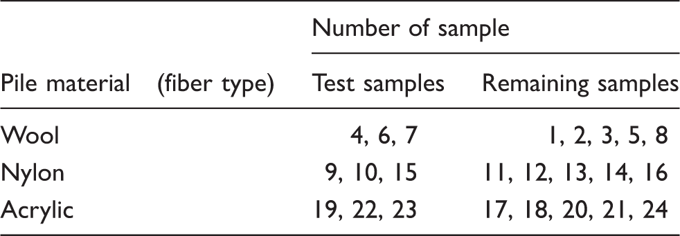
Sample arrangement for model verification.
In addition the primary backing used in this experiment was plain woven fabric made from 65 polyester/35 cotton yarns and has 108 × 108 yarns per 10 × 10 cm2 and weigh 0.365 kg/m2. The thermal resistance of the primary backing fabric was measured separately. All important yarn properties, including linear density, number of twists, and diameter of yarn, were determined. Yarn linear density was measured according to ISO 2060:1995. 20 The carpet yarns were wound on reel as skeins and weighted. The measurement was carried out under standard atmosphere (RH 65% ± 2%, 20 ± 2℃). Number of twist per length was evaluated by using the twist tester according to ISO 2061:2010(E), direct counting method. 21
Yarn diameter and external structure were evaluated by means of a microscope observation according to internal standard IN 22-102-01/01 for determination of yarn diameter and hairiness.
22
Figure 3 shows a representation of the arrangement for the yarn diameter and hairiness measurement.
Diagram of yarn diameter measurement using microscope observation.
22
The yarn diameters were measured randomly from the longitudinal views of the yarn by using image processing software. A special device (yarn guider) was allocated the yarn to move the yarn manually under the light microscope. This methodology is explained in detail in several articles.23–26
Procedure
The ALAMBETA instrument was used for determination of thermal resistance of cut pile carpets (RC) and primary backing fabric (RB). The principle of this computer controlled semi-automatic nondestructive thermal tester developed by Hes and Dolezal has been explained in various studies.12,16,27–29 Three carpet samples were randomly taken and their thermal resistance were measured for checking the accuracy of the theoretical model of thermal resistance of cut pile carpet. Regarding thermal resistance of remaining carpet samples, RC and primary backing fabric, RB were separately measured, then these values were substituted in equation (9) to calculated thermal resistance of yarn (RY) and equation (10) was used to calculate thermal conductivity along the yarn axis (
After calculating thermal conductivity along the yarn axis, thermal resistance of the yarn could be calculated by using equation (10). For this step thermal resistance of carpet was obtained from equation (7). Finally the actual thermal resistance values of test samples were compared with calculated values of remaining carpet samples.
Result and discussion
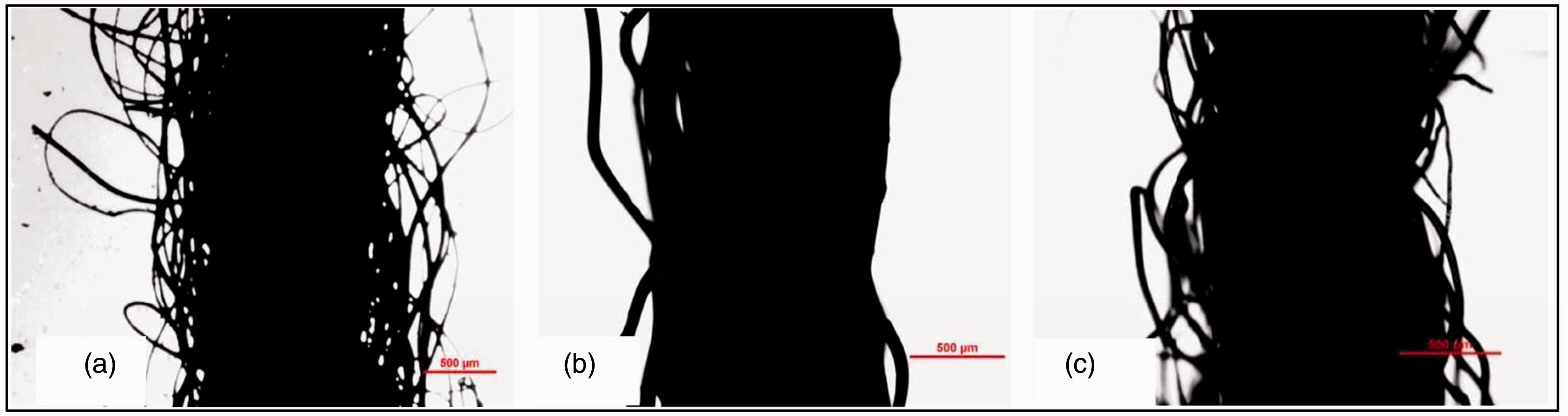
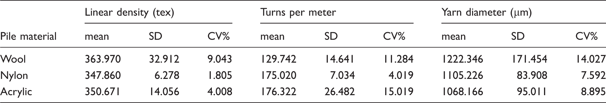
The basic property results of three types of pile material are shown in Table 3 and sample images of the external structure of yarn are also shown in Figure 4. Wool and acrylic are spun yarn. It is observed that wool yarn has highest linear density and diameter, and lowest turns per meter. Therefore wool yarn manufactured in the carpet sample is coarse hairy and bulky. On the other hand nylon, multifilament yarn is compact due to the structure itself and high turns per meter. The diameter results also show wool has high CV% on the diameter measurement. Therefore it might be affect to the prediction value.
Sample images of yarns: (a) wool, (b) nylon, and (c) acrylic Basic parameters of the used yarns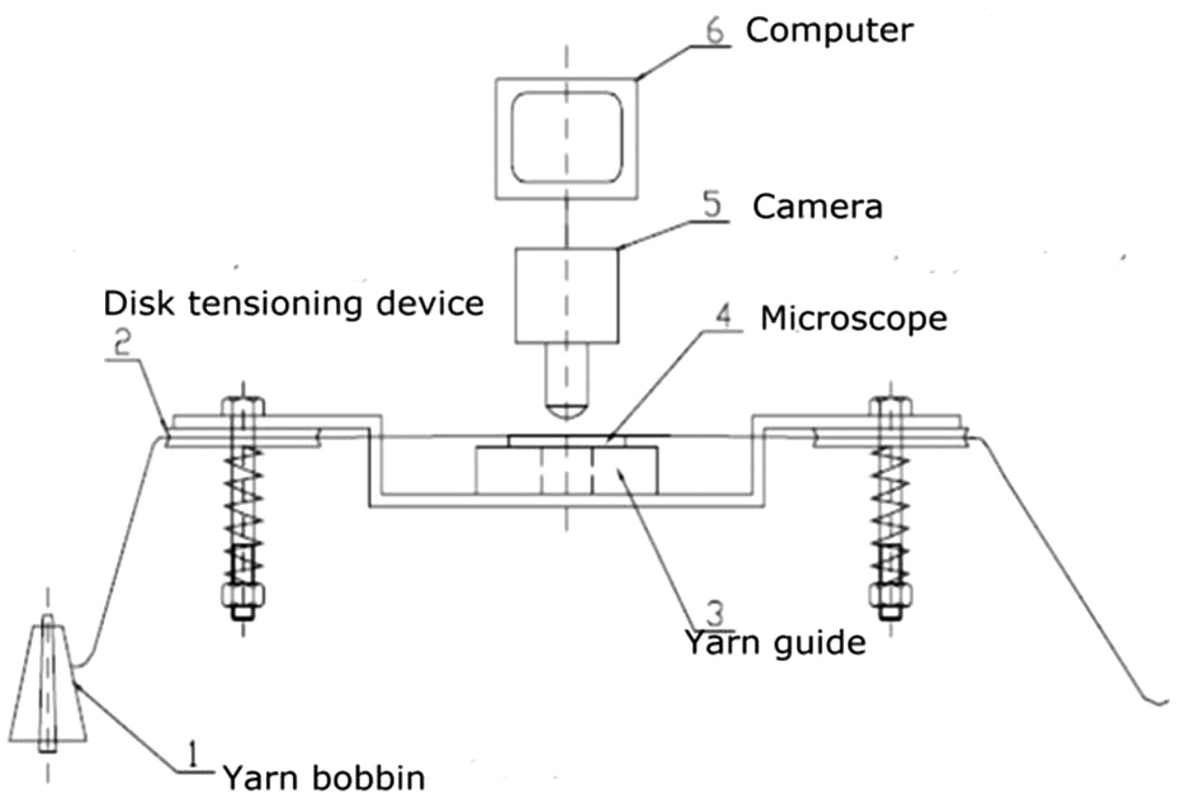
Theoretical thermal resistance and thermal conductivity of the yarn in the direction of the yarn axis.

RC: thermal resistance of carpet; RA: thermal resistance of air; RY: thermal resistance along the yarn axis;
Theoretical thermal resistance of cut pile carpet.

RC: thermal resistance of carpet; RA: thermal resistance of air; RY: thermal resistance along the yarn axis; RB: thermal resistance of primary backing fabric;
Calculated and measured results of thermal resistance of cut pile carpet assemblies.

Figure 5(a) show a comparison between the theoretical prediction and the experimental results for these sets of three carpets for each of the three pile yarns. It can be seen that the relationship is linear. The deviation of the slope of this line from unity indicates some error. Figure 5(b) plots the same data showing separate lines for the three different yarns and it indicates that the source of error is more for the bulky yarns of acrylic (slope 1.9973) and wool (slope 1.3442), whereas the nylon yarns gave very good match between the predicted and measured values (slope 1.0151). compact yarn structure of the nylon yarns, thus giving less error in diameter measurement. On the other hand, the relatively high errors in case of wool and acrylic could be due to the higher error resulting from the measurement of the diameter, which was evident from the diameter histogram for these materials which showed a broader range and multiple peaks, indicating a less uniform structure.
Comparison between predicted results and experimentally measured results: (a) all nine samples, (b) same data showing separate lines for different materials.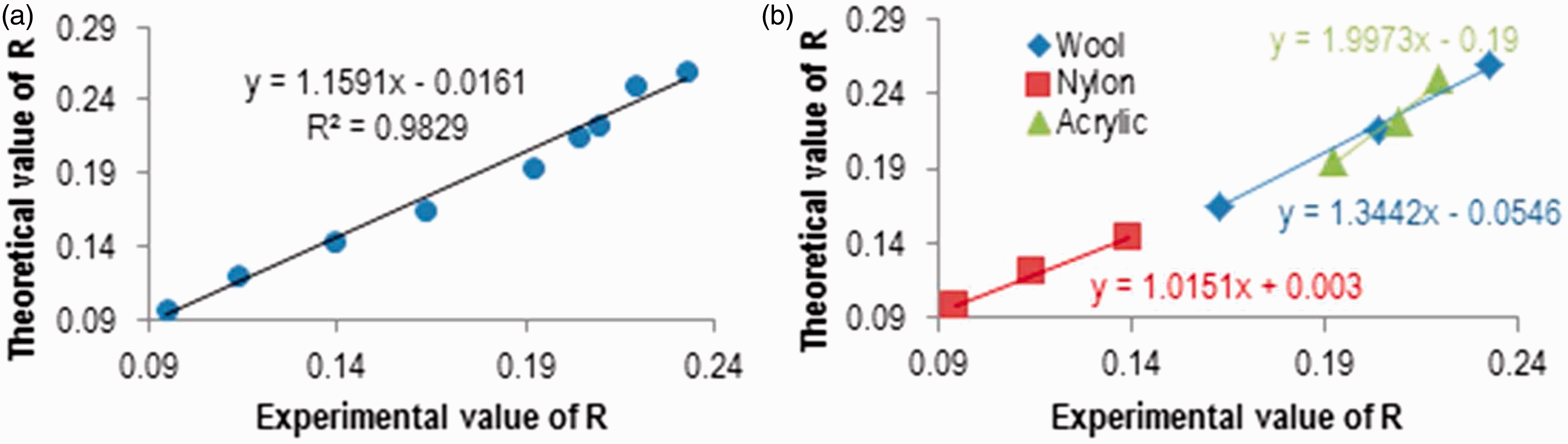
Conclusion
In this study, a structural model of cut pile carpet was developed and theoretical formulas for thermal conductivity and thermal resistance in the direction of the yarn axis were derived from cut pile carpet structure using theoretical thermal resistance of the yarn. The calculated values of thermal conductivity in the direction of yarn axis are consistent when compared with the same fiber type. Here, the determined thermal conductivity values of the yarn are quite low. This might be caused by the fact, that the yarn structure consists of great number of air gaps and these may affect the yarn thermal conductivity. The values of thermal resistance obtained from the developed theoretical model enable useful and consistent prediction of thermal resistance values when compared with the experimental data. However, although this general model is based on the geometry of cut pile structure, it may be used for Axminster or Wilton carpets which have, in particular, a cut pile structure. The situation will probably be more complicated for loop pile structures as modeling the loops would require consideration of heat flow in more than one direction since the loops do not have essentially linear geometry. Thermal radiation and convection are two other important modes of heat transfer although those modes were not considered in this study. However, a more complete model would require consideration of these other modes as well. Therefore, the next improvement of the presented model will consider heat transfer through the radiation and apply more components of the carpet such as adhesive and secondary backing fabric as part of the model.
Footnotes
Declaration of conflicting interests
The authors declared no potential conflicts of interest with respect to the research, authorship, and/or publication of this article.
Funding
The authors disclosed receipt of the following financial support for the research, authorship, and/or publication of this article: This work was supported in part by an SGS project (grant number SGS 21044) and an ESF project (grant number CZ.1.07/2.3.00/30.0065’).