
Abstract
Pneumatic yarn splicing is a complex process concerning the winding of multi-filaments in a spiral airflow field. In this study, the joint forming mechanism is revealed by experimental and numerical methods. The whole splicing process in a specific-design splicing device was captured by a high-speed camera. A renormalization-group k-
As a knot free joining method, pneumatic yarn splicing is being widely used in the textile industry for joining two separated yarn ends. 1 There are two processes in the operation of the pneumatic splicer, namely the untwisting process and the splicing process. During the untwisting process, the introduced two yarn ends are untwisted. Then, the two untwisted yarn ends are dragged into the mingling chamber and joined by an air blast to produce a neat spliced yarn. 2
For pursuing a good performance of spliced yarn, researchers have investigated the effect of splicing parameters on the performance of spliced yarn by experimental and analytical methods. Das et al. 3 reported the effect of the inlet pressure and splicing duration on the tensile properties of staple yarns from different spinning methods. In his work, ring yarns are most suitable for the splicing because of their helical structure that facilitating the good opening of fibers during pneumatic untwisting and thus proper intermingling during twisting. Rutkowski 4 compared the tenacity of spliced cotton yarn with two different linear densities. Baykaldi et al. 5 carried out several trials to study parameters such as twist factor, linear densities and splicing duration on the breaking strength, elongation and diameter of spliced elastane /cotton blended core yarns. To investigate the contribution of the spandex core to the splice appearance of wet pneumatic elastic denim core-spun yarn, Jaouachi et al. 6 discussed the influences of the overlapping length and splicing duration of water joining by an image analysis method.
Many researchers also aim at predicting the splice quality or optimizing the splicing parameters using the experimental design method. Employing an artificial neural network and response surface models, Ünal et al.7,8 established the relationship between process parameters and the diameter of spliced yarn. Jaouachi et al. 9 adopted fuzzy logic theory to develop a forecast model that predicts the mechanical properties of splicing according to the input process parameters. Webb et al. 10 used Taguchi’s experimental method to obtain optimized geometric parameters of the splicer that yield a strong splice. By adopting MINTAB software, Moqeet et al. 11 elucidated the effects of different yarn splicing parameters on the strength, elongation and appearance of spliced yarn and put forward an optimal combination of splicing variables. Dayik 12 employed gene expression programming to conjecture the breaking strength of yarn and compared the effectiveness of the prediction with statistical regression and neural network algorithms.
The airflow characteristics in the pneumatic splicer play a decisive role in the forming of the joint and its performance. Therefore, computational fluid dynamics (CFD) was used by researchers to simulate the distribution of airflow field for explaining the relationship between process or structural parameters and the performance of spliced yarn. Zhou et al. 13 combined the UG software and Fluent solver to study splicing performance with a three-dimensional splicer model. To study the movement of fibers in the untwisting chamber, Xing and Ye 14 addressed the characteristics of the airflow pattern in different parts of the chamber, adopting the commercial CFD software FLUENT. By analyzing airflow in the pneumatic splicer with different structures and sizes, Wang et al. 15 optimized the structural parameters of the mingling chamber. From the analysis of the effects of a groove structure on airflow characteristics in the mingling chamber and the splice strength, Wu et al. 16 clarified the effectiveness of the groove in improving the splice performance. In recent years, the fluid–structure interaction (FSI) algorithm based on the CFD method has become increasingly popular in simulating the motion of a flexible body in airflow. Qi 17 developed a model to simulate the suspension behavior of a filament in low Reynolds number flow. Taking the spinning process as a research object, Pei et al. 18 and Gao et al. 19 simulated motion of a single filament in spiral airflow. Vahidkhah and Abdollahi 20 used an immersed boundary method to study the deformation of flexible fiber in a viscous flow. However, it is not realistic to use this method to analyze the splicing process as it involves the contact–impact dynamics and FSI between numerous filaments and complex airflow field during splicing, which would cost large computational resource.
Researchers have mainly focused on investigating the effect of the process and structure parameters on joint performance. Because the splicing of two separated yarns is achieved by entangling each other among filaments, the macroscopic performance of spliced yarn is determined by the winding behavior of filaments at the mesoscopic scale. There are few literatures concerning the filament motion during the pneumatic yarn splicing. In 2010, Webb et al. 21 used the visualization method to observe a typical splicing process and presented a final photograph of spliced yarn. Wu et al. 22 developed a wrapped model and tried to deduce the relationship between the airflow field and strength of spliced yarn via this model. However, the detailed splicing process and related filament motion in splicing chamber still have not been fully discussed.
This study was carried out to investigate the joint forming mechanism by analyzing the motion of the filament in the spiral airflow field. A specific splicing device in transparent plastic was manufactured. Based on a high-speed camera, a visualization test bench was established to record the splicing process. In addition, a turbulent mathematical model was adopted to describe the airflow field in the mingling chamber. The motion and deformation behavior of a large aspect filament were analyzed in detail according to the experimental images and the numerical results of the airflow field. Furthermore, the effect of overlapping length and inlet pressure on the splicing process was discussed. Finally, experiments with varying overlapping length and inlet pressure were conducted to verify the analysis results.
Simulation and experimental methods
Preparation of materials and devices
Figure 1 presents a schematic diagram of the pneumatic splicer. As seen Figure 1(a), two opposite experimental yarns consisting of parallel filaments are introduced into a mingling chamber with an overlapping manner, and each yarn is fixed at one end by an ends retraction level. Figure 1(b) shows the overlapping relationship of the two experimental yarns. The free-ends of filaments are parallel to the opposite filaments. Air inlets 1 and 2 represent central symmetric distribution, which is covered by the middle part of the filaments. After an airflow injects into the mingling chamber from the air inlet, a spiral airflow forms due to the geometric structure of the chamber, which impels the free-ends of filaments to wind around the filaments of the opposite yarn.
Schematic diagram of the pneumatic splicer.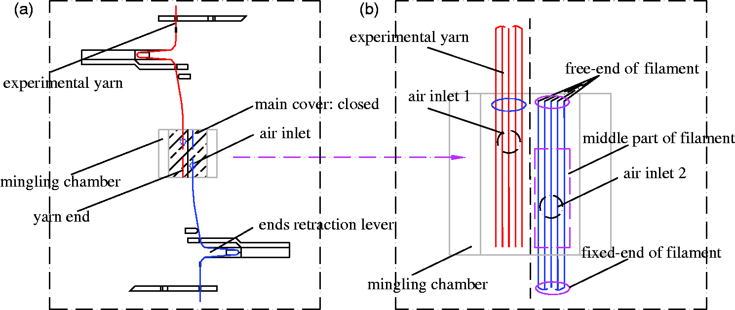
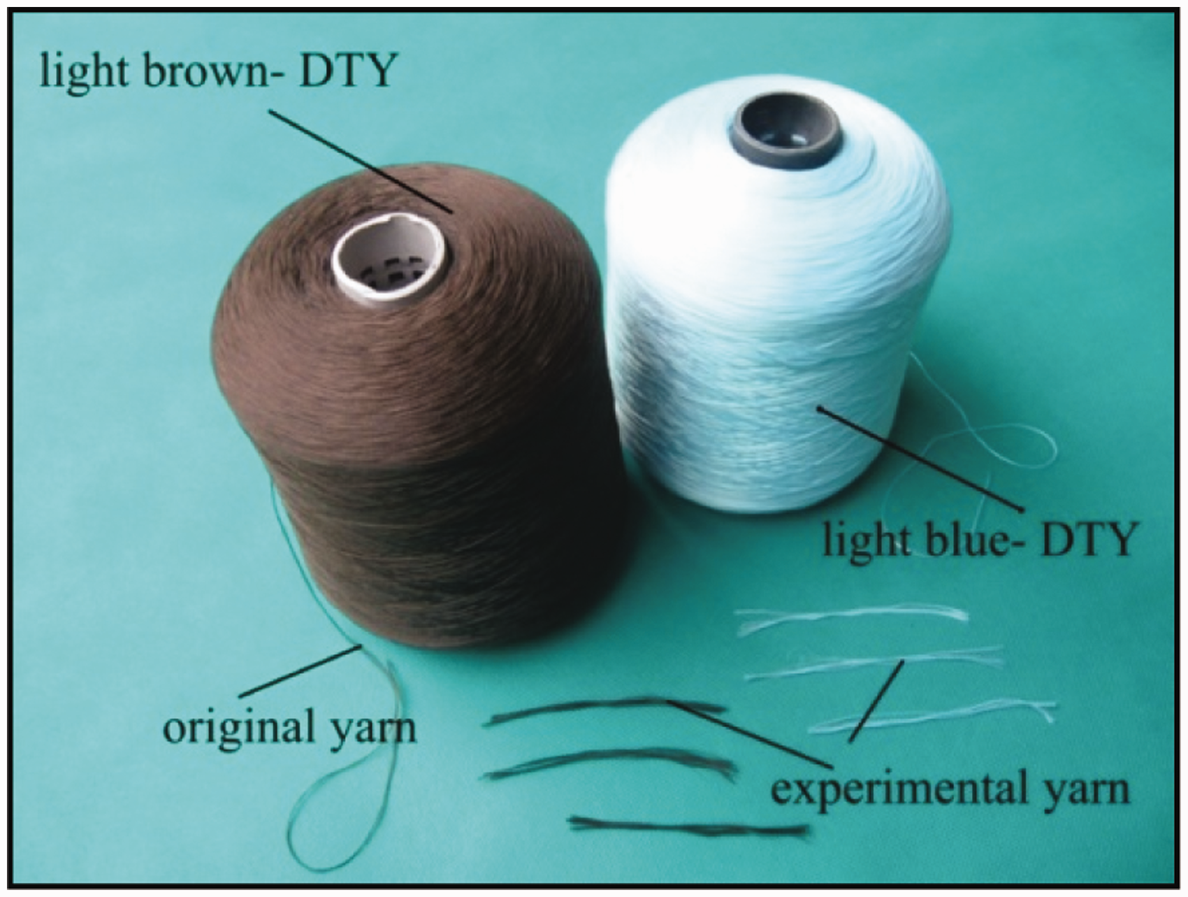
Because of main cover is sealed during splicing and the speed of airflow is very high, the process of splicing is difficult to capture. Therefore, a transparent splicing device was custom designed in this experiment. The device, shown in Figure 2, was manufactured on a scale of 2:1 in size and constructed from a type of transparent plastic (polymethyl methacrylate). A fixed plate in this device was applied instead of the ends retraction lever (plotted in Figure 1(a)) to fix one end of the yarn sample. A cover plate was used to replace the main cover (plotted in Figure 1(a)) to close the mingling chamber, which makes observation more convenient and clearer. As shown in Figure 3, a polyester draw texturing yarn comprising 96 filaments was used as the experimental sample. Yarn count is 300 D and filament fineness is 3.125 D. By experimental measurement, its elastic modulus ( Picture of experimental splicing device. Picture of experimental yarn samples.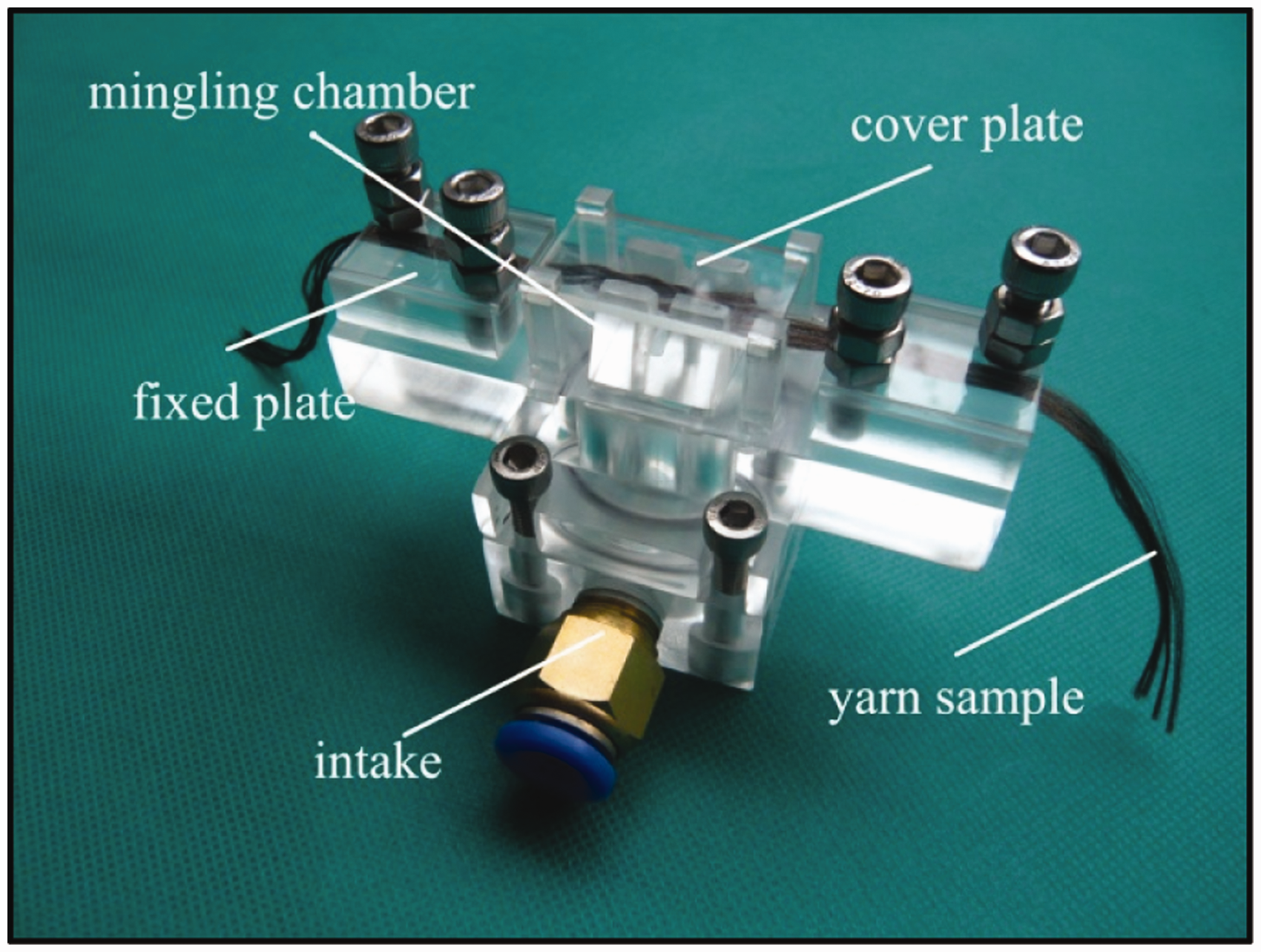
Numerical simulation
For the sake of analyzing the motion characteristic of the filaments, a commercial CFD software, FLUENT, was adopted to simulate the airflow pattern in the mingling chamber. Figure 4 shows a three-dimensional geometric model of the mingling chamber and the corresponding fluid domain divided into the inlet channel, accelerating channel, groove channel and rotating channel.
Photograph of the geometric model and fluid domain of the mingling chamber.
A mixed meshing strategy with tetrahedral and hexahedral elements was used for the discrete fluid domain. In addition, because the splicing process is a very quick, a three-dimensional, transient, compressible, and viscous airflow is considered. Navier–Stokes equations are adopted as the governing equations for the airflow domain:

The mass conservation equation is


The energy equation is

The renormalization-group k-ɛ turbulence model was applied to describe the characteristics of airflow in the mingling chamber. Both outlets of the rotating channel and the groove channel were set as the static pressure outlet condition at 1 atm, and the inlet of the inlet channel is defined as the pressure inlet condition. No slip and adiabatic boundary condition were assigned to the walls of the simulation model. The discretization equations were solved by the Semi-Implicit method for a pressure linked equation. In addition, the convergence absolute criterion for numerical calculation is defined as that the residual value of energy quantity is less than 1E-6 and each other physical quantity is less than 1E-3.
Visual experimental bench
Figure 5 shows the experimental apparatus of the visualization test bench, which includes an air compressor, a pressure regulator, a solenoid valve, a gasholder, a stage light, the splicing device, etc. The intake solenoid valve mounted on the gasholder was applied to control the splicing duration, and the air inlet pressure Schematic diagram of the experimental bench for observing the progress of yarn splicing.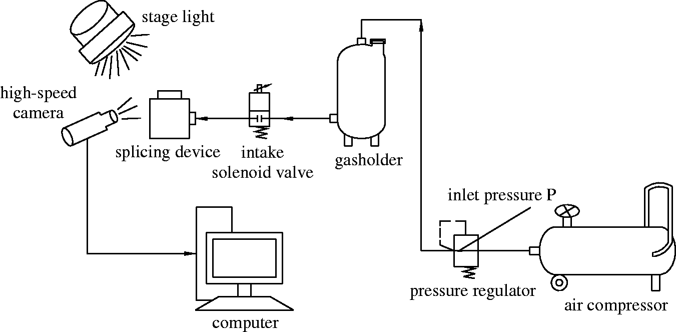
Results and discussion
Analysis of the airflow pattern
Figure 6 presents the flow trajectories of compressed air in the mingling chamber. As can be seen, once compressed air injects into the rotating channel from the air inlet, a jet flow acts as a radial airflow flowing into the rotating channel. Then with the collision and rebounding against the circular wall, the radial airflow transforms into a circumferential airflow. Moreover, because of the pressure difference between the outlet and the internal channel, an axial airflow is generated. Finally, the resultant circumferential and axial airflow works as spiral airflow. After that, the spiral airflow flows out from the four outlets. Clearly, the circumferential force of the spiral airflow will impel the free-ends of filaments to wind around the opposite filaments.
Flow trajectories in the mingling chamber.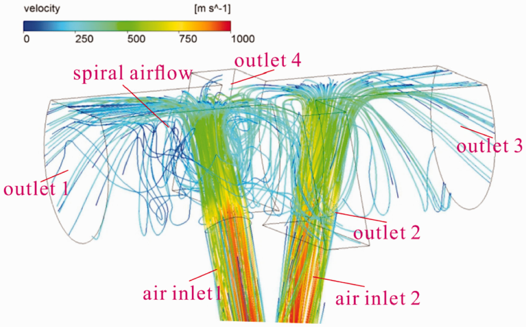
Apparently, the motion of filaments in this complex airflow field, which can be adjusted by the overlapping length, air inlet pressure and splicing duration, would determine whether a joint can be achieved successfully. Therefore, it will revealed how the airflow drives the filaments and how the process parameters affect the joint forming mechanism in the following.
Analysis of the filament motion and joint forming mechanism
Figure 7 reports a whole splicing process of multi-filaments under the conditions of overlapping length ( Splicing behavior of multi-filaments during yarn splicing (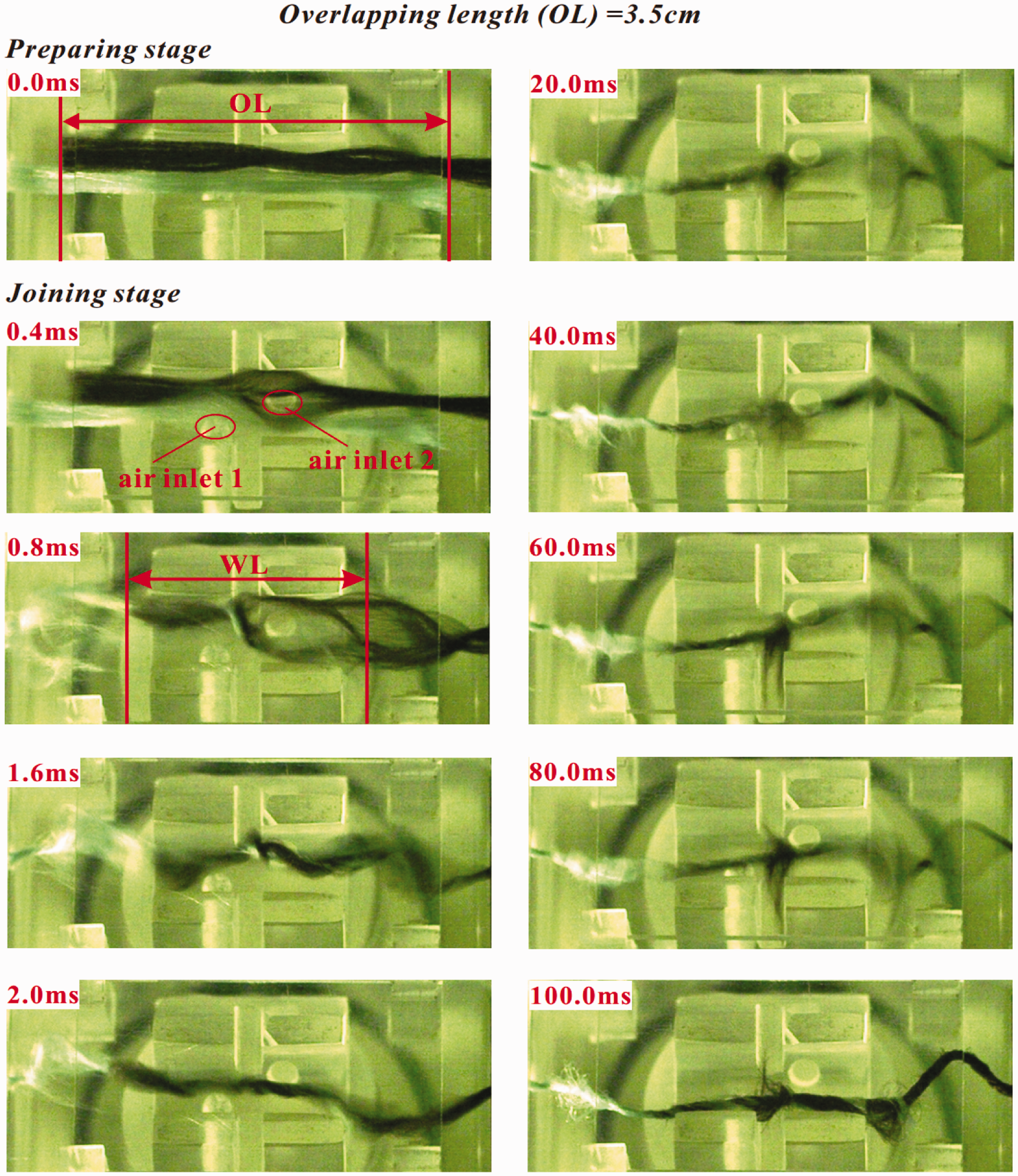
For further explaining splicing behavior observed in the visualization experiments, the effect of the spiral airflow on the flexible filament is discussed with the assistance of numerical results from the CFD model. Figure 8 presents the schematic diagram of multi-filaments in the preparing stage. As can be seen, two experimental yarns are overlapped with a pre-set overlapping length, and each experimental yarn is fixed at one end. The air inlet is covered by the middle part of yarn, while the free-ends of this yarn have an offset distance with another air inlet.
Schematic diagram of multi-filaments in the preparing stage.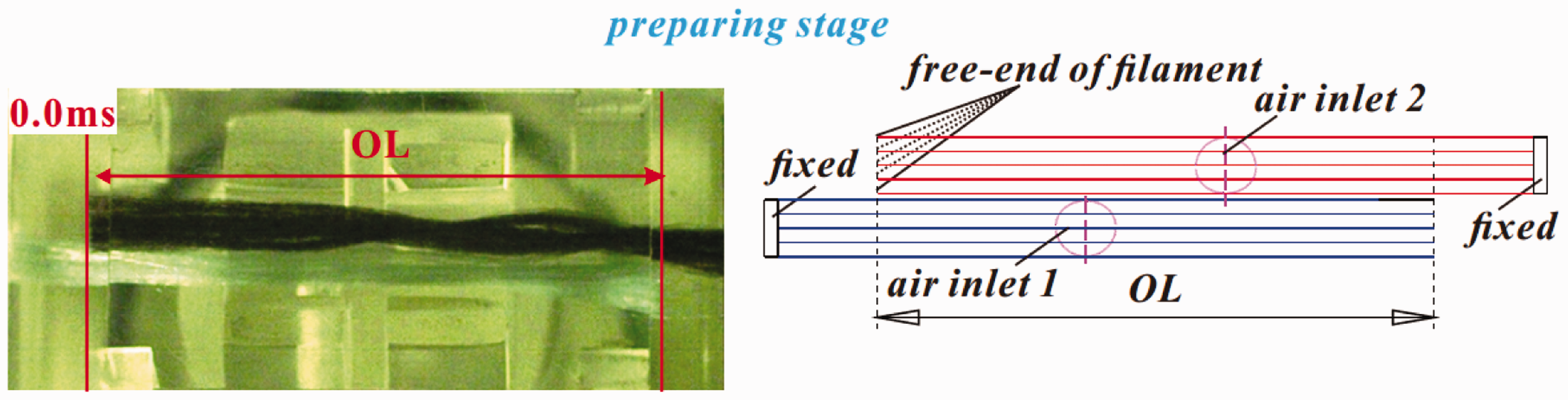
Because the airflow enters the rotating channel from the air inlet, the cross-section A-A of the rotating channel, which includes the air inlet and corresponding acceleration channel, is sliced, as seen in Figure 9(a). The velocity distribution in the cross-section from the numerical model is presented in Figure 9(b). While the airflow injects from the air inlet, it directly strikes the wall and then divides into two circumferential airflows. It is observed that circumferential airflow in the clockwise direction is larger than that in the counterclockwise direction, which dominates the circumferential force in the clockwise direction which will drive the movement of filaments. Because the air inlet is covered by the filaments, bending deformation occurs at the middle part of filaments near the air inlet under the impact of the impact force Schematic diagram of filament dispersing behavior in the joining stage.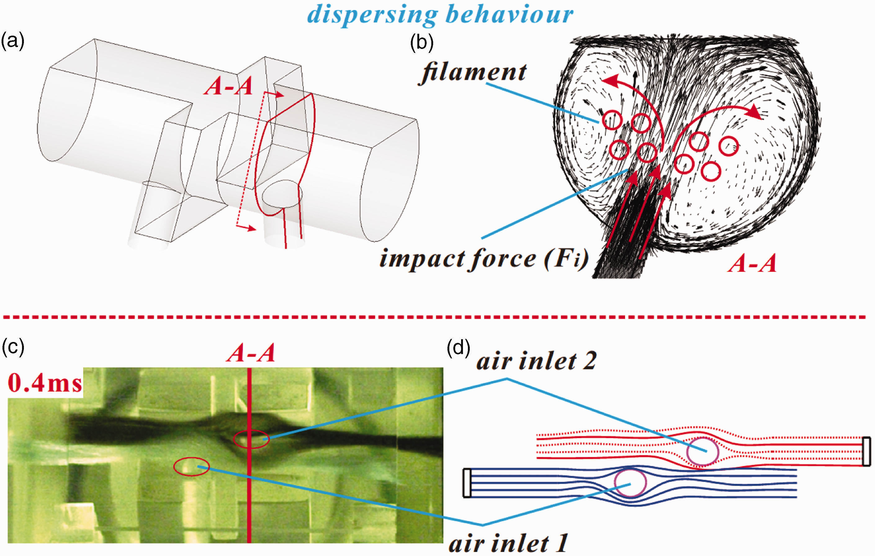
To simplify the drawing, the typical filaments, which are marked as red solid lines, are selected to analyze the forming of the joint in Figure 10. With the increase of the bending deformation of the filaments in the middle part, the axial airflow in the rotating channel starts to influence the motion of filaments. An obvious axial airflow can be observed in Figure 10(b), which presents the velocity distribution in the longitudinal profile of section B-B, marked with red cross-hatching in Figure 10(a). Taking the light brown yarn in Figures 10(c) as an example, the left-hand part of the filament relative to air inlet 2 sustains force Schematic diagram of dragging behavior in the joining stage. (Color online only.)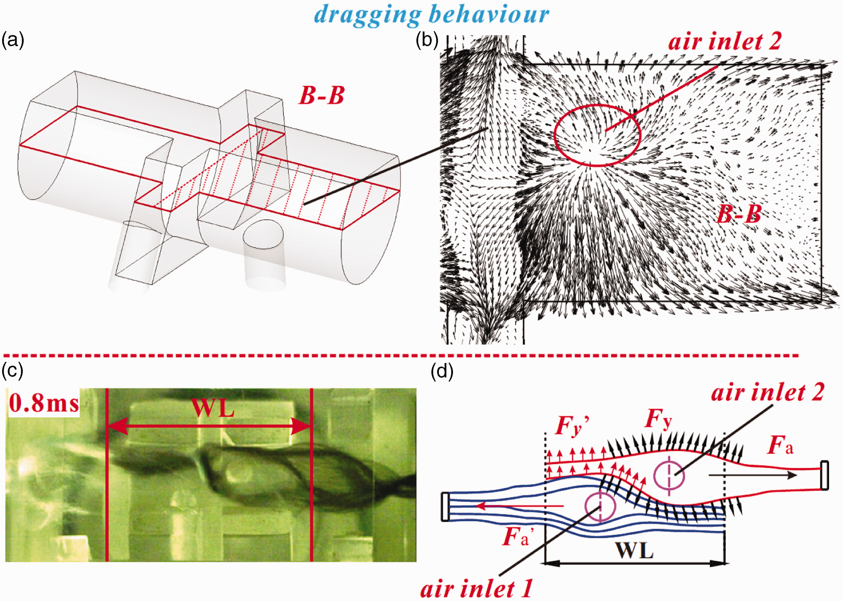
If there are no other forces worked on the filaments in this moment, the overlapped two filaments would directly separate from the mingling chamber, which causes a failing splicing. While, as plotted in Figure 11(b), an apparent circumferential airflow along the clockwise direction in the cross-section C-C (marked with red cross-hatching in Figure 11(a)) is formed, which impels the free-ends of the filaments to wind around the opposite filaments in a helical manner, as shown in Figures 11(c) and (d). It provides necessary friction force Schematic diagram of wrapping behavior in the joining stage. (Color online only.)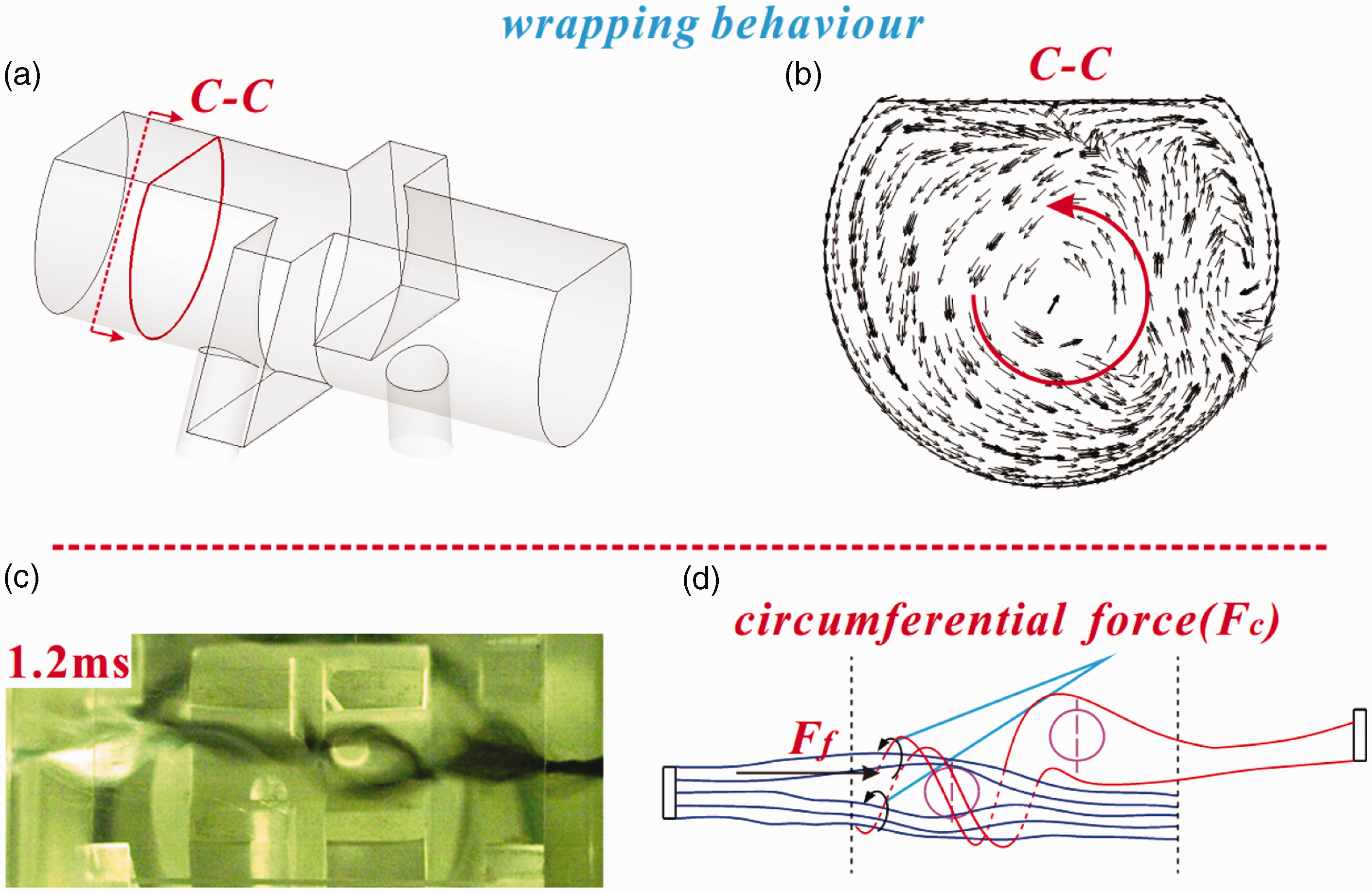
Figure 12 illustrates the motion of filaments in the splicing process with different overlapping lengths. In this schematic diagram, Figure 12(a) represents the condition of the small overlapping length and Figure 12(b) reflects the condition of the longer overlapping length. In addition, to describe the filament motion more clearly, the filaments are plotted with a red line to illustrate the forming of joint in this figure. As plotted in Figure 12(2), after the high-speed airflow injects into the rotating channel from the accelerating channel, the filaments that cover the air inlet are blown to the walls of the channel and the bending deformation occurs at the middle part of the filaments. Depending on the constraint type of the ends, two parts of the filaments divided by the air inlet presents totally different motion behavior under the impact of axial airflow. One part with free-end tends to be straightened by the axial airflow and its force bearing area decreases, while the force bearing area of the part with the fixed-end continuously increases. Therefore, the filament is dragged to its fixed-end by the axial force exerted by airflow, as illustrating in Figure 12(3). It is clear that the winding length for Figure 12(a (3)) is smaller than that for Figure 12(b (3)), which constrains the winding loops of filaments. As plotted in Figure 12(4), the free-end of the filament quickly winds around the opposite filaments to try to form an initial winding under the impact of circumferential flow coming from the opposite air inlet. Obviously, the initial joint plotted in Figure 12(b (4)) is superior to that in Figure 12(a (4)) due to more winding loops. Once a proper initial joint is established, the joint continues to be compacted by circumferential force, while the initial joint breaks if the friction force provided by the initial winding could not tower over the dragging force, as reflected by comparing Figures 12(a (5)) and (b(5)).
Schematic diagram of the compared filament motion under various 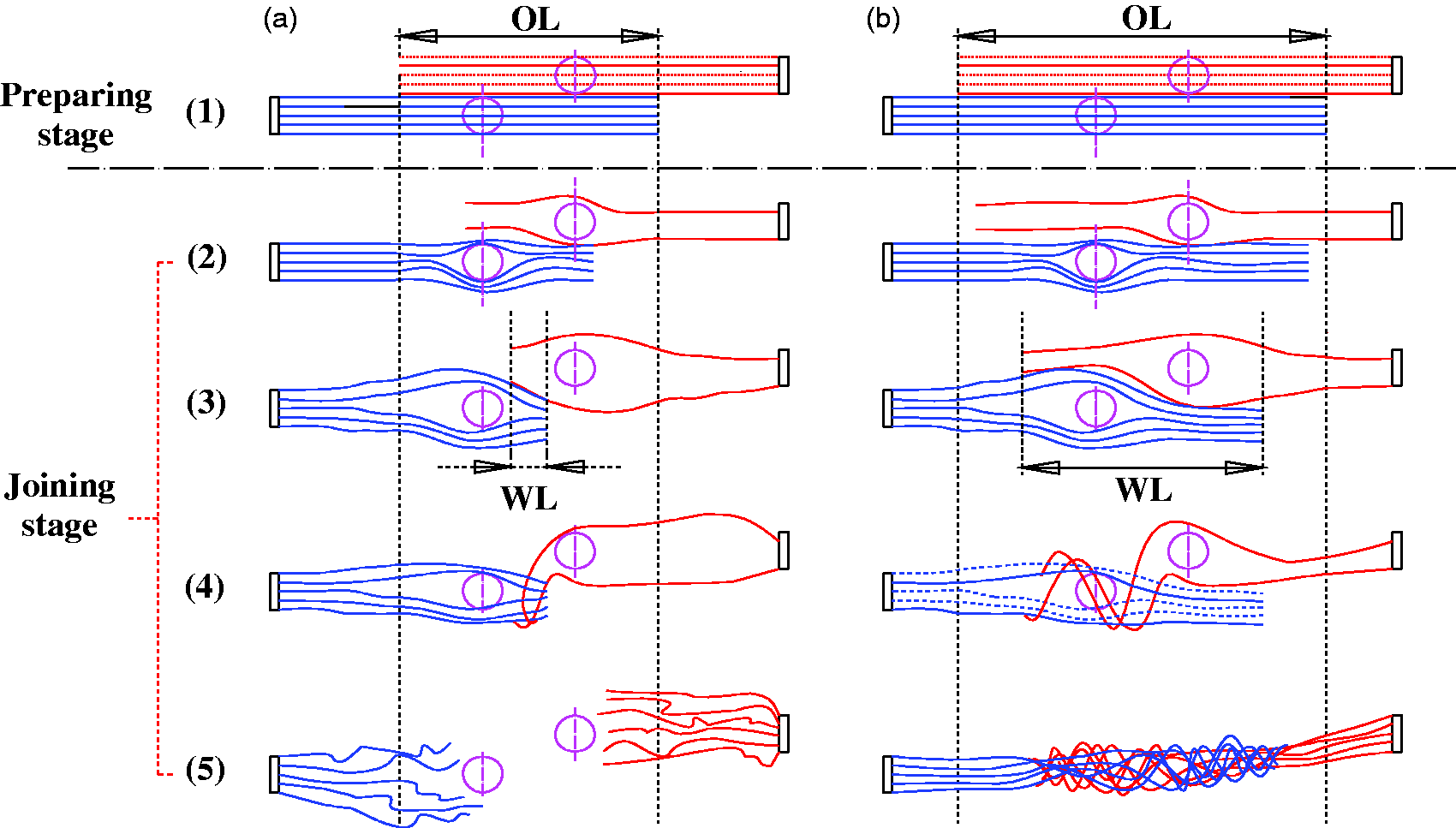
According to the preceding analysis, it is believed that the overlapping length is a key parameter because the proper overlapping length produces enough winding length to provide necessary friction force between two yarns to resist the dragging force. The inlet pressure determining the airflow pattern in a given mingling chamber is also an important process parameter. To verify the influence of the two parameters on the splicing process, the splicing experiments with different overlapping length and inlet pressure were conducted to compare their winding length and, consequently, the splicing results showing whether two yarns can be successfully spliced are given in the following.
Effect of the overlapping length on joint forming
Figure 13 shows the splicing process of multi-filaments under the conditions of inlet pressure ( Splicing process under different overlapping lengths (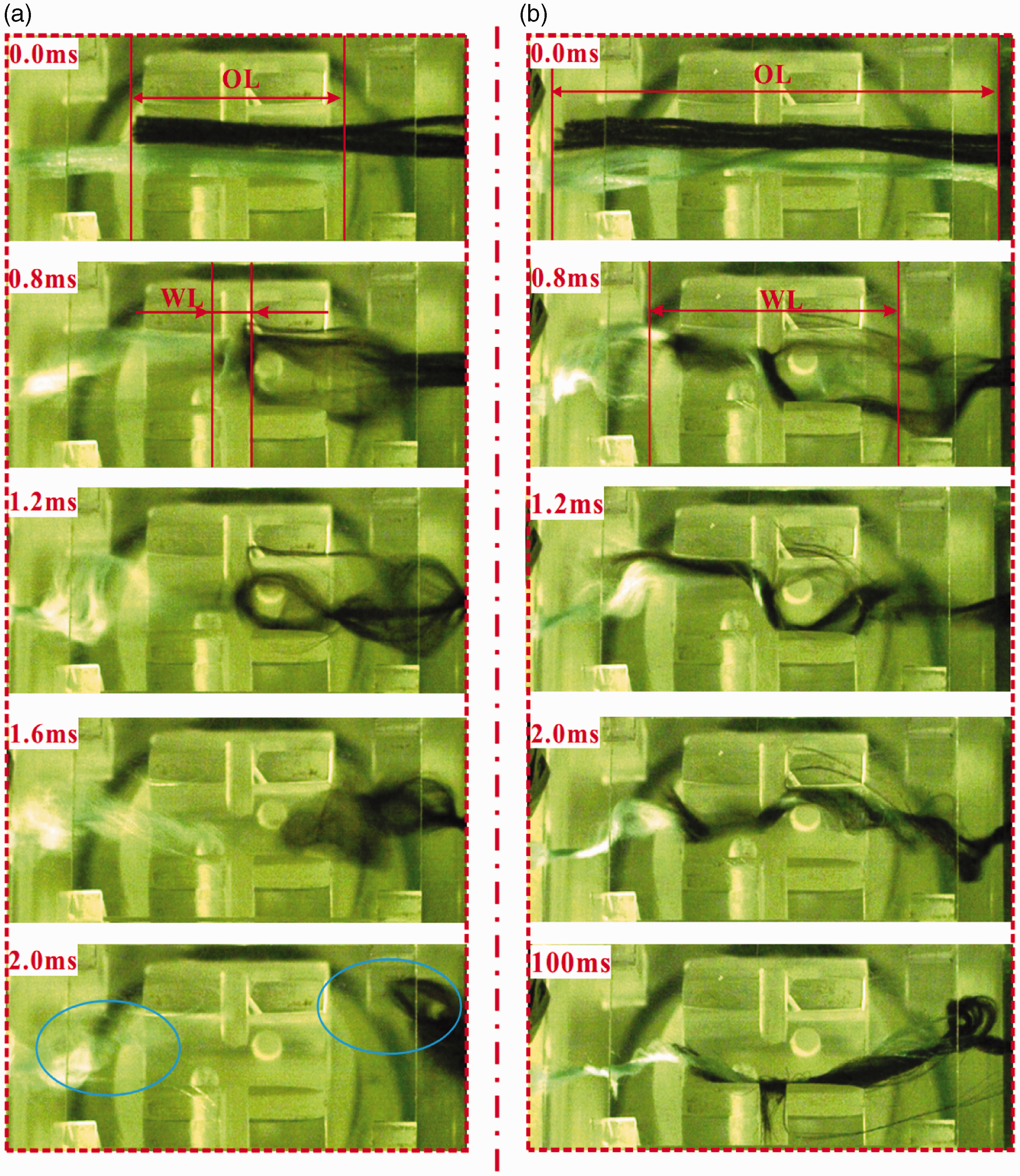
To further study the effect of overlapping length on the joint forming, experiments for three overlapping length conditions with other three different inlet pressures ranging from 4 to 6 atm at intervals of 1 atm were conducted.
Figure 14 presents the splicing processes with three different inlet pressures under the same overlapping length (2 cm). As can be seen, the same filament motion as in the preceding experiments is observed again. At 0.8 ms, the winding lengths under the three inlet pressures are 0.554, 0.412 and 0.323 cm respectively. However, none of them can obtain a successful joint.
Splicing process under different inlet pressures (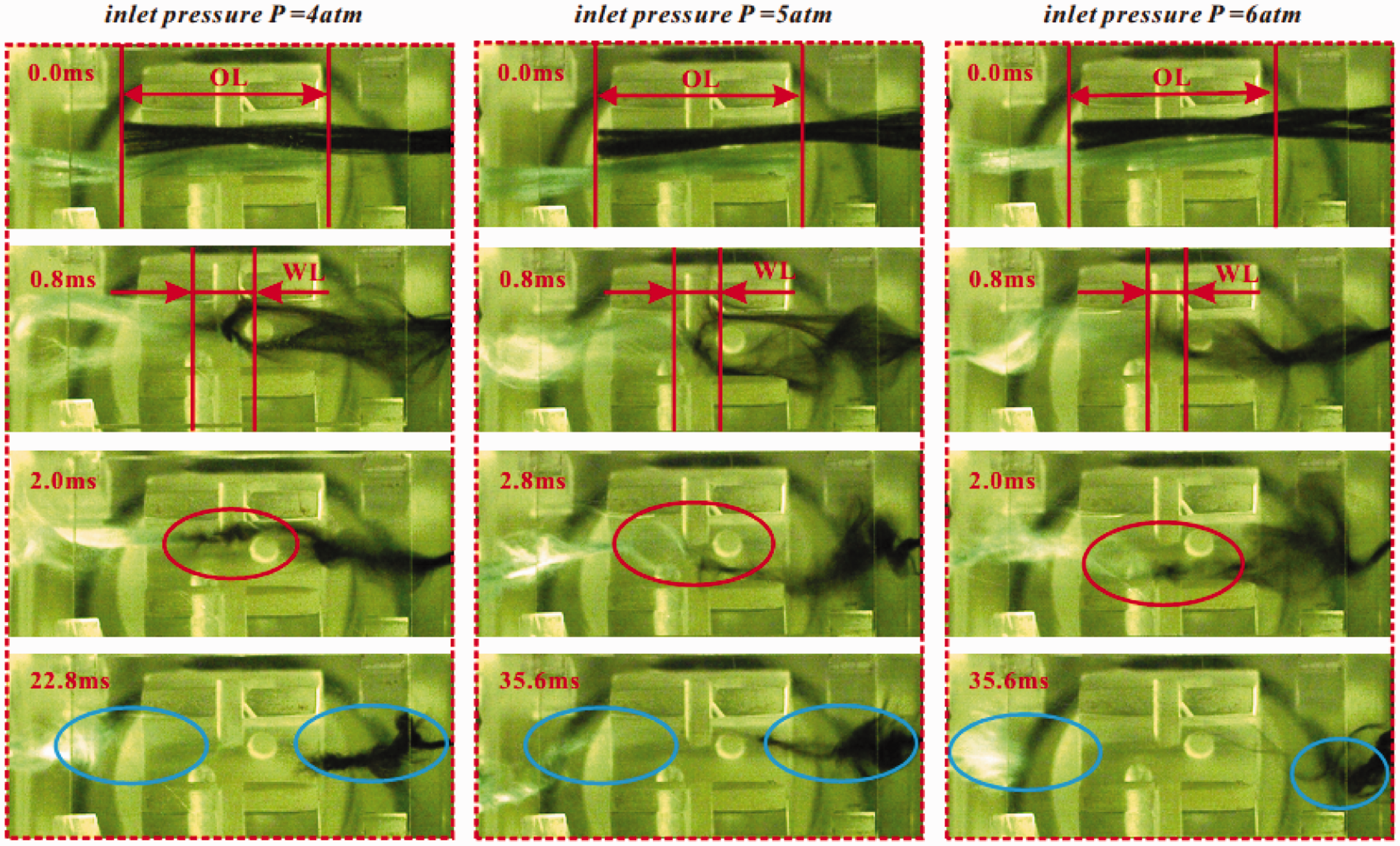
Figure 15 presents the process of splicing for Splicing process under different inlet pressures (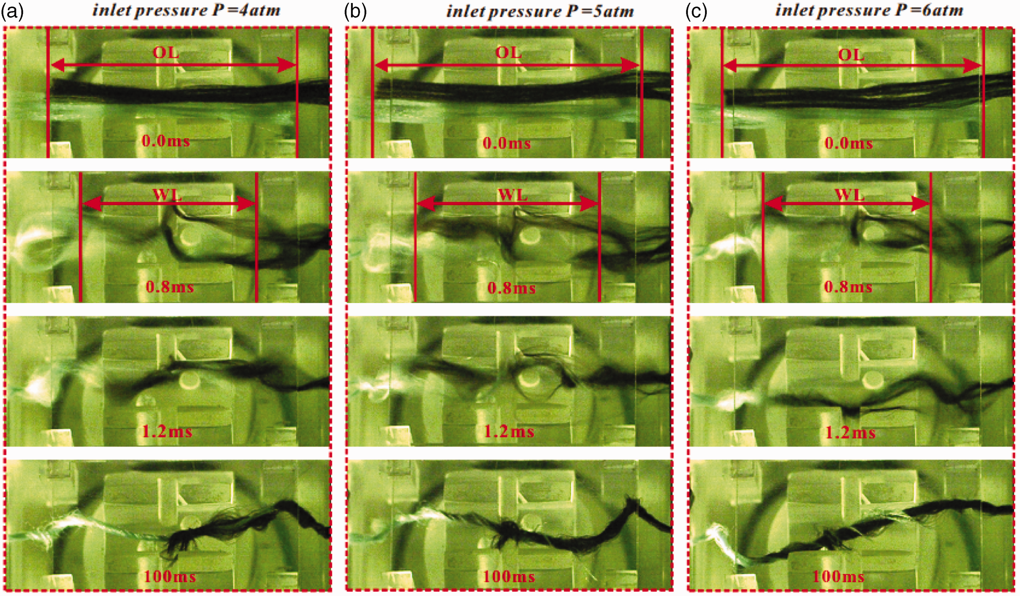
Continuing to increase the splice length, as shown in Figure 16, two opposing yarns are introduced into the mingling chamber with Splicing process under different inlet pressures (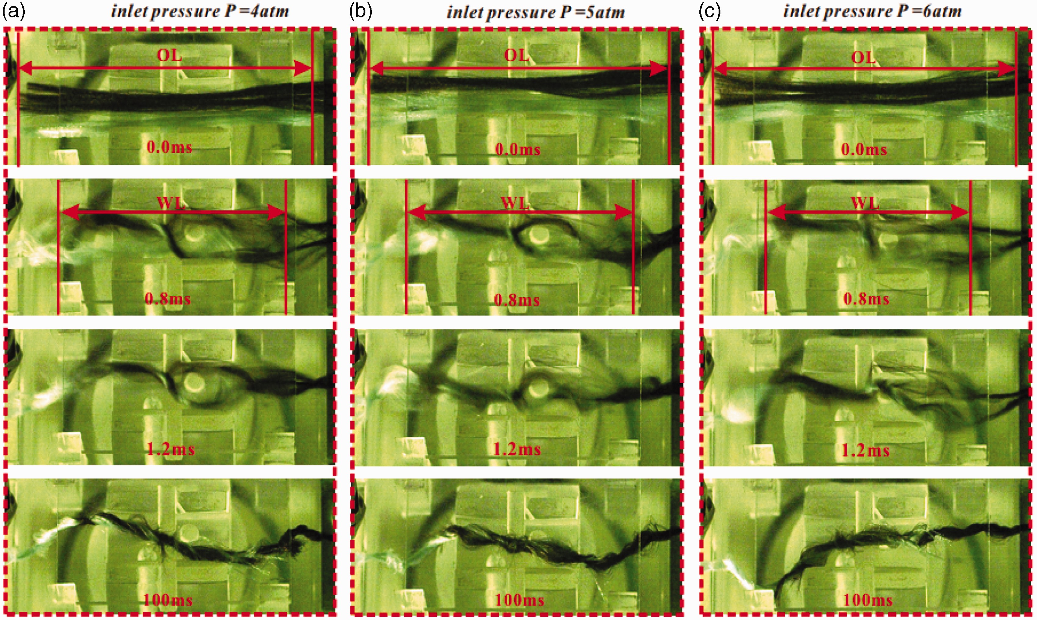
The comparison of the three groups of experimental results also shows that inlet pressure has a feebler role on obtaining a successful joint relative to overlapping length. This result is caused by the simultaneous influence of inlet pressure on filament winding and yarn separation. The increasing inlet pressure improves the strength of the spiral airflow in the circumferential direction, and hence a stronger circumferential force would be obtained to impel the free-ends of filaments to wind around the opposite filaments more quickly and compactly. On the other hand, the increasing inlet pressure also enhances the axial airflow, which induces stronger drag force to separate the two yarns. Therefore, the effect of inlet pressure on the splice behavior and the joint forming has advantages and disadvantages.
Conclusions
The aim of this work is to study the joint forming mechanism by investigating the motion of filaments in the mingling chamber. A computational fluid dynamic model was adapted to analyze the distribution of airflow. In addition, a full splicing process in the transparent specific splicing device recorded by a high-speed camera was reported in this paper. By comparing the numerical results and filament-motion pictures, the motion and deformation behavior of filaments is analyzed in detail.
It is concluded that the setting of splicing duration is relatively weaken for the forming of joint. What is more, during the whole process, the first 2 ms is a critical period because it determines whether a successful joint can be achieved.
With the assistance of numerical results of the airflow field, it is also found that filaments present a totally different motion behavior at their different parts. An obvious bending deformation occurs in the middle part of filaments due to the impact force from injecting airflow. One part with free-end tends to be straightened by the axial airflow and its axial force bearing area decreases, while the axial force bearing area of the part with the fixed-end continuously increases. Therefore, the filament is dragged to its fixed-end by the axial force and two yarns are separated by airflow. At the same time, the free-end of the filament quickly winds around the opposite filaments to form an initial winding joint under the impact of circumferential flow. Whether a successful joint can be obtained depends on the comparison between friction force provided by the initial winding joint and axial force for separating yarns.
Furthermore, a series of splicing experiments under varying inlet pressures and overlapping length conditions were done to verify that a longer overlapping length is of benefit to generate a longer winding length, and an easier winding could be obtained. If the overlapping length is smaller, it may cause a weak winding and even disconnected condition. It is also revealed that the effect of overlapping length is more significant than inlet pressure to promote the forming of the joint.
This theoretical study can also be used to optimize the structural and process parameters of the pneumatic splicer. Although compared with the overlapping length, inlet pressure plays a feebler role to obtain a successful joint, but with the increasing of inlet pressure, the yarn strength, yarn elongation and yarn appearance would change accordingly. Because of the limits of paper length, we will study these in the follow-up work.
Footnotes
Declaration of conflicting interests
The authors declared no potential conflicts of interest with respect to the research, authorship and/or publication of this article.
Funding
The authors disclosed receipt of the following financial support for the research, authorship, and/or publication of this article: The authors gratefully acknowledge the National Natural Science Foundation of China No.51275482 and the 521 Talent Project of Zhejiang Sci-Tech University financial supports.