
Abstract
Spacer fabrics are very attractive nowadays for use as technical fabrics. Our interest in this study is to give geometrical models for weft-knitted spacer fabrics which can be used in related engineering software. Models of two commonly used weft-knitted spacer fabrics are created here based on Kurbak’s 1998 plain knit model and are drawn to scale using the 3DS-MAX computer graphical program. It is observed that similar shapes to the real fabrics are obtained by the models.
Spacer fabrics, in general, are obtained by having two layers of single fabrics, and these two layers are connected by some yarns or some single fabrics. There are mainly two groups of spacer fabrics; namely weft-knitted and warp-knitted spacer fabrics. Warp-knitted spacer fabrics are out of the scope of this paper; therefore, they are not mentioned hereafter. Traditional weft-knitted spacer fabrics are made on double-bed, flat or circular knitting machines by knitting two single-jersey (plain) fabrics at the same time with at least two different yarns on either bed at the back bed (or dial) and in the front bed (or cylinder) and connecting them by a third yarn which makes only tuck stitches at the back bed and in the front bed. Knitting instructions of the two most widely used weft-knitted spacer fabrics are given in Figure 1.
Knitting instructions for weft-knitted spacer fabrics: (a) with rib gaiting and (b) with interlock gaiting.
A photograph of a weft-knitted spacer fabric is given in Figure 2.
Photograph of a weft-knitted spacer fabric: (a) front view and (b) cross-sectional view.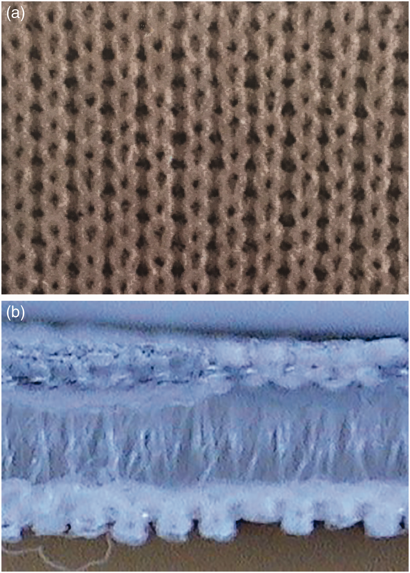
Some other kinds of spacer fabrics, which are similar to the classical ones but instead of the yarns connecting the two fabric faces some single fabric parts connect the two surfaces, have also been developed to use as technical fabrics. These fabrics are also out of the scope of this work.
In the last decade, the technical potential of spacer fabrics has been distinguished and the properties have been improved for various technical applications. Some of the applications are outlined below.
Because of their higher recovery properties when a compression is applied on their surfaces and because of their cushioning effect, they are used inside the heel of sports shoes. Because the gaps between the two layers (of the fabrics) make them highly water-absorbent and softer, they are used as pads, nappies, surgery pads, etc. The formability, softness, elastic recovery, mechanical, noise reduction and thermal insulation properties of the spacer fabrics allow them to be use inside vehicles (cars, busses, etc.) Because the two layers of the fabrics are connected by some connecting yarns, higher lamination properties are obtained when they are used as the reinforcing fabric materials in textile composites. The two layers of spacer fabrics can be different; therefore, they can be used for items such as sportswear because of their transfer wicking properties and also for their higher microclimatic properties between the skin and the fabric. They can be used as electromagnetic shielding fabrics. They can be used as liquid cooling garment by inserting “tubes” between the layers. They can be used as heating garments by inserting conductive yarns or wires inside the layers. They can be used for the reinforcing materials, for items such as lightweight cement composites.
The above mentioned physical properties of spacer fabrics have been investigated experimentally in accordance with their application areas. At the same time some software engineering computer programs have being created for the estimation of the physical properties of textile fabrics. These software programs need full definitions of the geometrical properties of the fabrics used. As far as we know, there is no such properly-defined geometrical model created for weft-knitted spacer fabrics. Therefore, this work is aimed at creating geometrical models for at least the very basic weft-knitted spacer fabrics, of which the knitting instructions are given in Figure 1.
There are, however, some geometrical models that have been created for the plain-knitted fabrics and for structures that have tuck stitches. In this context, the models of Chamberlain, 1 Pierce, 2 Leaf and Glaskin, 3 Leaf, 4 Munden, 5 Postle, 6 Kurbak, 7 Kurbak and Ekmen, 8 Kurbak and Amreeva, 9 Alpyıldız and Kurbak 10 and Kurbak and Alpyıldız11–14 can be counted. These models were investigated to see if some of them could be used for the basis of the work for the present models. The models of Kurbak and his colleagues7–14 have been seen to be suitable for the present purpose; therefore, the present models will be based on the models created by Kurbak and his colleagues.7–14
Creations of the models
Two models were created. Schematic pictures of the models are provided in Figure 3.
Schematic pictures of the weft-knitted spacer fabric: (a) with rib gaiting and (b) with interlock gaiting.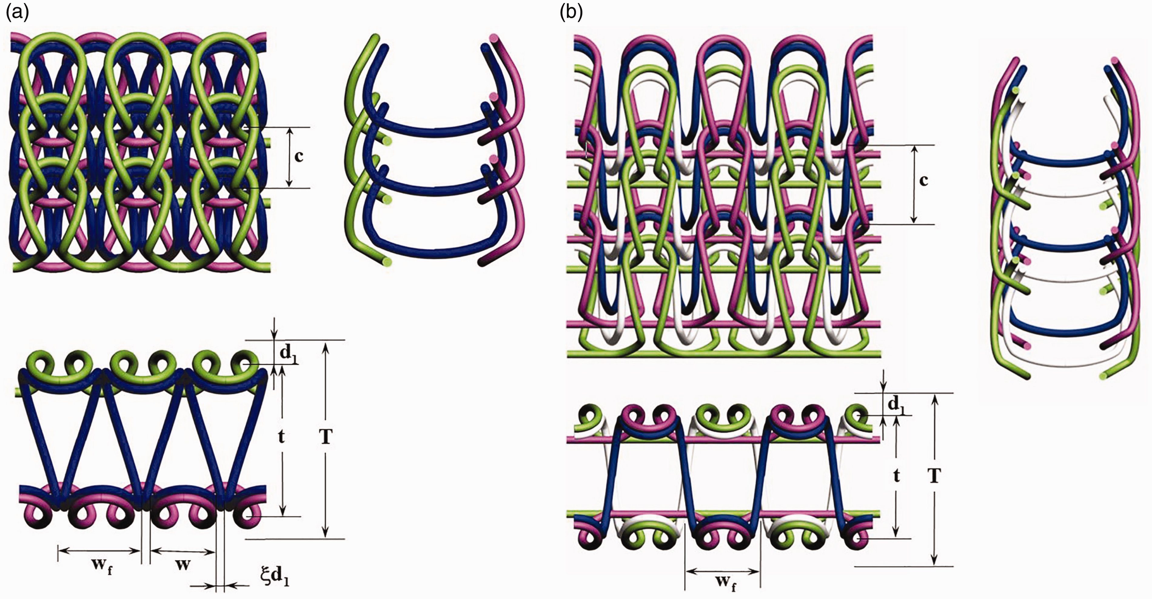
Modeling of the fabric faces
In these models, the front and back faces are taken as the same, using the same yarn counts. Fabric faces are modeled based on the 1 × 1 rib models of Kurbak
15
and Kurbak and Alpyıldız.
14
That is, loop heads and loop arms are the same as in the 1 × 1 rib model in which the loop heads are elliptical curves and the loop arms are modeled by having vertical circular cylinders and wrapping the yarns axis on these cylinders using the parabolic equation below

During applications of the parabolic curves on cylinders, the helix angles at two ends of the cylinders are different as in the 1 × 1 rib model.
The models of plain-knitted fabrics on the faces of the spacer fabric are given in Figure 4.
Model of the plain-knitted fabric which is used at the faces of weft-knitted spacer fabrics: (a) with rib gaiting and (b) with interlock gaiting.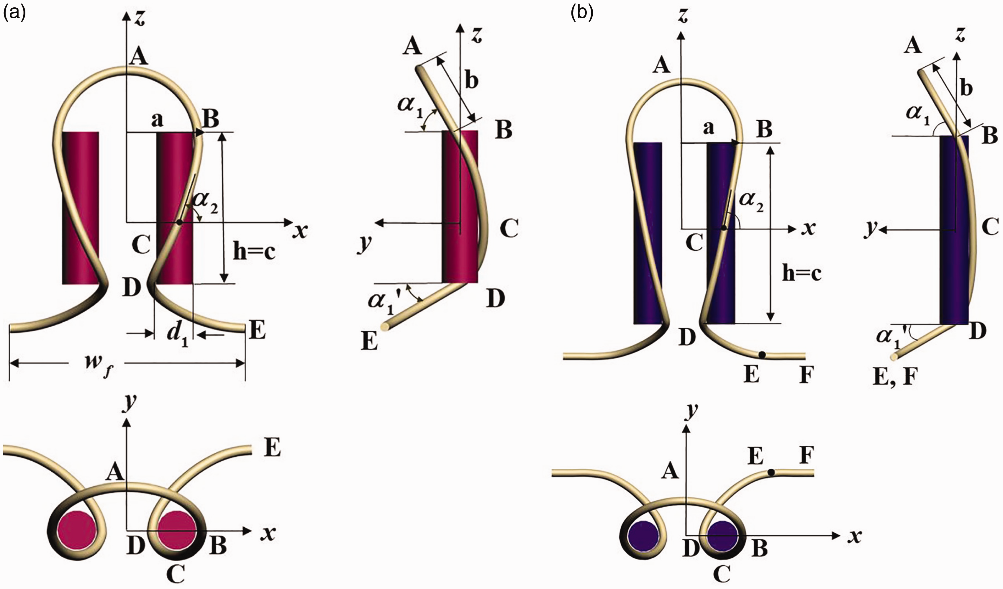
In Figure 4, for the helix angle at the upper end,
Considerations for the faces of the weft-knitted spacer fabric with rib gaiting
First of all, the feet of the loops are wider than the loop heads. For this situation, a wale spacing w is defined, and then at the position of two feet of loops,


The major radius of the loop feet is

In addition to the above widening for accommodating the tuck stitch of the connected yarn in the fabric thickness direction, an elliptical cone given in Figure 5 is used at the legs of the plain loops.
Elliptical cone defined for obtaining the lower ends of the plain loops.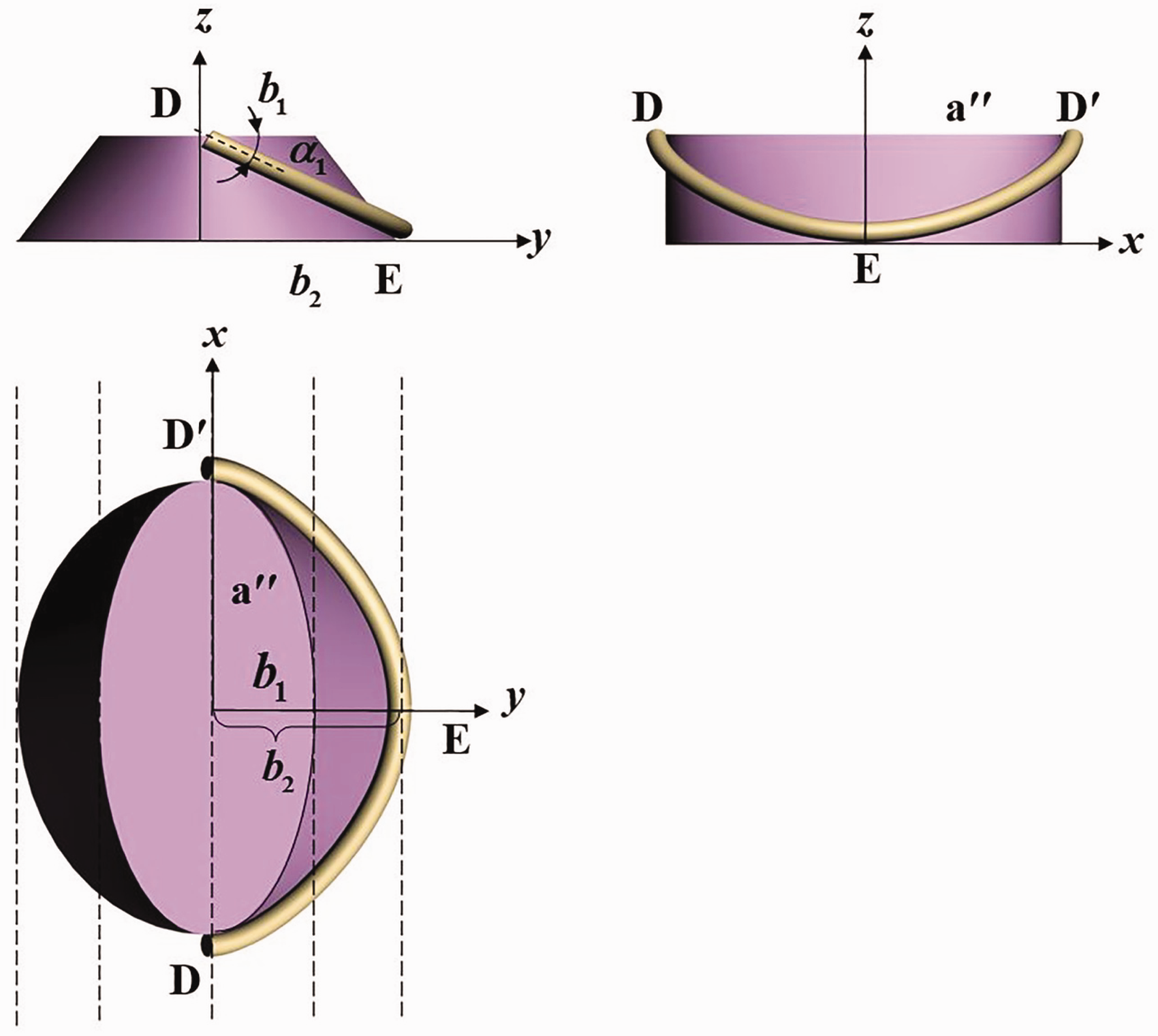
The equations of the intersecting curve of the defined cone and DE plane in Figure 5 is obtained as


This curve given by equations (5)–(8) is used as the plain loop feet. In equations (5)–(8), b1 is found from the curvature equalities at point D as

From equation (9), b1 is obtained as

The parameter b2 can be changed in accordance with the diameter of the connecting yarn d2. Therefore the present models are versatile ones and can be used for connecting yarn of any yarn diameter. In this work, a parameter η is defined to consider the diameter of the connecting yarn as

The parameter
If the above considerations are not enough and there are still some crossing yarns in the model, then b2 is increased while a″ is decreased. In this case, it is thought that yarns in these sections are stretched; thus, some straight horizontal yarn sections are added to the feet to complete the original wale spacing (wf).
Considerations for the faces of the weft-knitted spacer fabric with interlock gaiting
The same considerations used for the weft-knitted spacer fabric with rib gaiting are used for the case with interlock gaiting, and a horizontal straight yarn path, which is equal to wf, is added in the middle of the sinker loop (at the loop foot) as seen in Figure 4(b).
Modeling of the connecting tuck stitches
The connecting tuck stitches between the front and the back faces of the present spacer fabrics are modeled as given in Figure 6.
The present model for the tuck stitch and the connection yarn sections of the weft-knitted spacer fabrics: (a) with rib gaiting and (b) with interlock gaiting.
The imaginary yarn wrapping cylinder diameters are taken as d1.
The model is explained in parts as given in the following section.
Tuck stitch head for rib and interlock gaiting
The tuck stitch head (AB in Figure 6) is modeled by having an elliptical curve leaning toward the inner side of the fabric, in the fabric thickness direction, as seen in Figure 7.
The tuck stitch head of the weft-knitted spacer fabric.
The equations of the tuck stitch head are given by


The parameter
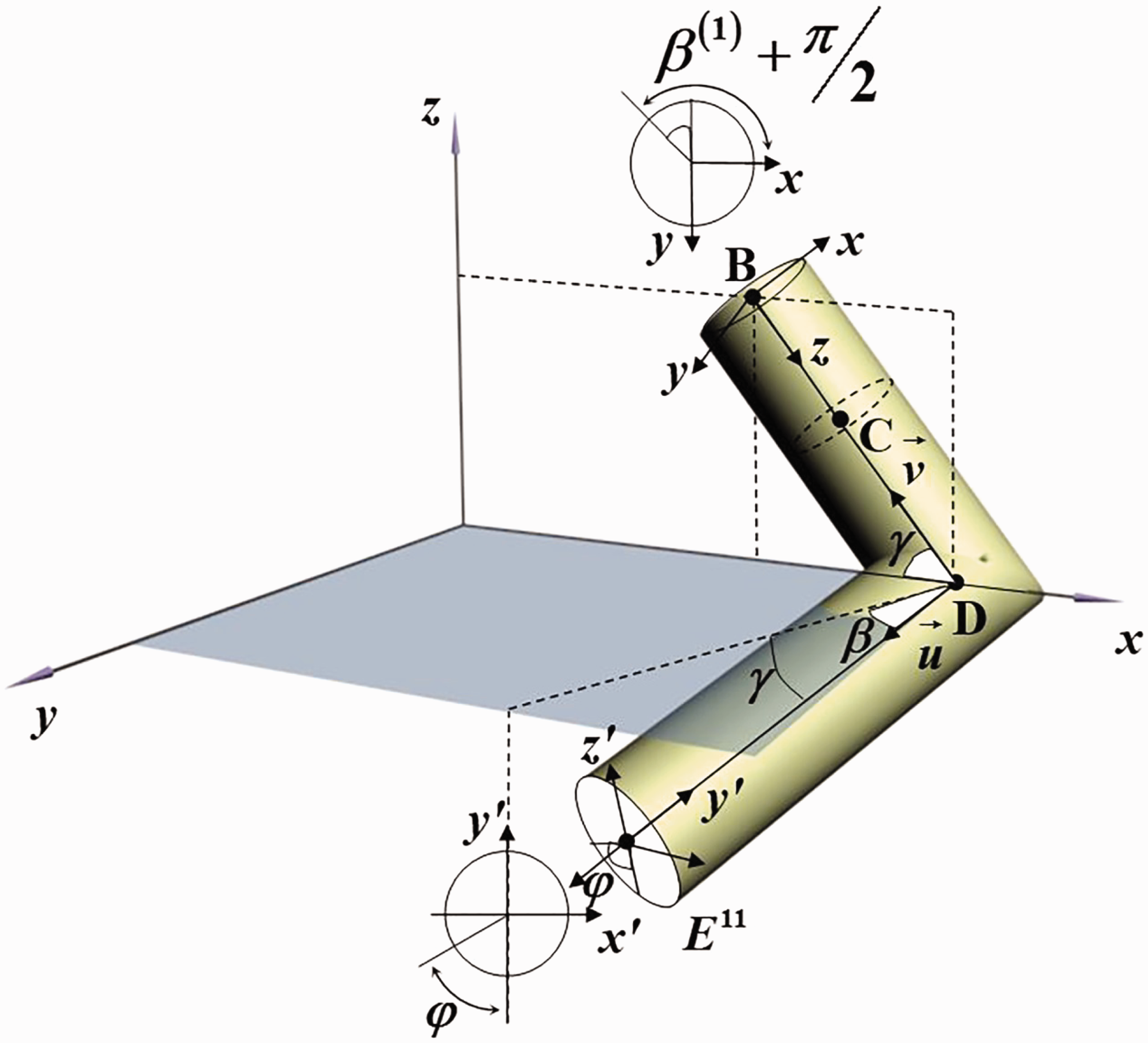
Tuck stitch arm for interlock gaiting
The tuck stitch arm (BCD in Figure 6(b)) is modeled by wrapping the yarn axis on a circular cylinder which is situated in the fabric plane and by making an angle γ with horizontal x-axis (Figures 6(b) and 8).
The right-hand side arm of the tuck stitch of the weft-knitted spacer fabric with interlock gaiting.
At point B, the tangent of the upper curve and the arm curve should be equal to each other to obtain a continuous curve; therefore, the following equation can be written

Again, at point B, the radii of the curvatures of the two intersecting curves should be equal; therefore, the following equation is applied

The third equation is the equality of the XB coordinate at B which can be written as

In this model, two adjacent tuck stitches in the same face are assumed to be touching each other for the rib gaiting. To satisfy this statement, the following equation is written for the wale spacing of the tuck stitch

Equation (18) is assumed to apply for interlock gaiting as well, even though the touching condition is not the case for interlock gaiting.
Instead of using lengthy calculations, the parameter
From the above discussion, the

Thus, if the height of the tuck stitch is denoted by ct, then an expression for γ can be written as

For dry relaxed fabric, the following equation is assumed to apply

By using equations (15)–(17) and equation (20), the parameters a, b,
The length of cylinder 1 (in Figure 8) can be given by

In order to draw the tuck stitch arm, other parameters are needed, namely the wrapping angle
Equations (15)–(22) are also used to calculate the tuck stitch arms of the spacer fabric with rib gaiting.
Connecting yarn section for rib gaiting
The connecting yarn section (DE in Figure 6(a)) is modeled in three steps. First of all, a circular cylinder is considered, and the yarn axis is wrapped on this cylinder using equation (1) (see Figure 9(a)). Secondly, this cylinder with the wrapped yarn is bent so that the final shape becomes a part of a torus with radius R (see Figure 9(b). Thirdly the torus is placed in between the front and the back fabric faces making an angle β with the normal direction of the fabric plane as given in Figure 9(c).
Modeling of the connecting yarn parts of the weft-knitted spacer fabrics: (a) yarn wrap on a straight cylinder, (b) straight cylinder bent together with wrap yarns on ıt into a torus shape and (c) torus placed between the front and the back faces (r2 = r = d1/2 is used).
From Figure 9(c), we can calculate h2 and β as


Figure 9(c) does not show it, but there is
t is the distance between the two faces of the spacer fabric, and

It can be shown that the unit tangent vector

The unit vector of the tuck stitch arm DB at D is

The scalar product of these two vectors

Since the radii of imaginary cylinders 1 and 2 (see Figure 13 in the Appendix) are equal to each other, from the curvature equality, the helix angle of the wrapped yarn at D can be given by the equation

It should be noted here that if the sign of the scalar product
The calculation of the maximum wrapping angle

We thought that if we assume a small angle
In this case, if we assume that
Therefore, in this study, for relaxed spacer fabrics, the helix angle
For the above assumed case (


Since the unknown parameters
If the helix angle
The parameter


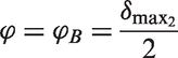
The maximum wrapping angle δmax2 of the connected yarn between B′E′F′ in Figure 9(a) can be given by

The calculation of equation (36) is also given in the Appendix together with the parameter
Correction factor for α3
While bending the straight rod into the torus shape, the length of the central axis of the rod does not change, but the outer side extends and the inner side contracts. This situation creates a problem if the starting point of the parabolic curve on the rod (at D and F in Figure 9(b)) is not at the central axis of the rod. Instead of having
From Figure 9(c), the following equation can be written

From the geometry,


We already know that

Therefore, the following equation is obtained

In equation (41), the following can be written for point D
Therefore, the correction factor at point D can be written as

When we put the correction factor into equation (41), we obtain

It became clear from the above discussion that, if we want helix angle
Because of the symmetry the helix angles,

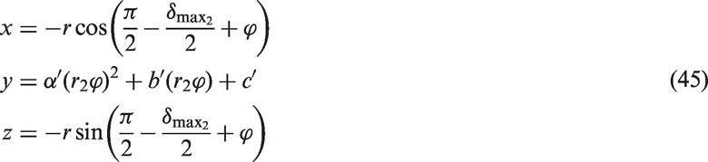
When the straight cylinder in Figure 9(a) is bent to the torus shape given in Figure 9(b), the equations for the parabolic curve for
Again, the equations of the curve between D and E in Figure 9(c) can be written in the

Connecting yarn section with interlock gaiting
The present model for the connecting yarn section (DE in Figure 6(b)) of the weft-knitted spacer fabric with interlock gaiting is given in Figure 6(b). To obtain this model, the very same equations for the model of the connecting yarn section (DE in Figure 6b) of the weft-knitted spacer fabric with rib gaiting are used except that the parameter β is taken as zero. Therefore, the calculations of the model are not given here. Equation (18) is assumed (and is used) to consider the widths of the tuck stitches of the weft-knitted spacer fabric with interlock gaiting as well, although the touching of the adjacent tuck stitches in the same face are not applied in this case.
Results
The three-dimensional models created for the weft-knitted spacer fabrics are drawn to scale using the 3DS-MAX computer graphical program and given in Figure 10. It is seen that the shapes obtained by the models are very similar with the shapes observed in the real fabrics. The parameters used to draw the models are as below:
The parameters used to draw the model given in Figure 10(a) for the weft-knitted spacer fabrics with rib gaiting are The parameters used to draw the model given in Figure 10(b) for the weft-knitted spacer fabric with interlock gaiting are Weft-knitted spacer fabric drawn to scale using the 3DS-MAX computer program according to the present model: (a) with rib gating and (b) with interlock gaiting.

Discussion on the widths and lengths of the tuck stitches
During the calculations of the tuck stitches, in equation (18), the wale spacing wf is used instead of w; therefore, there are some openings occur between the adjacent face loops. The reason for using wf was that if we use a normal wale spacing (w), the maximum width points of the tuck stitches would be at the upper side of them instead of at point D. In most of the spacer fabrics, however, the openings between the face loops are visible. Therefore, in the present models, the parameter The tuck stitches placed on top of each other.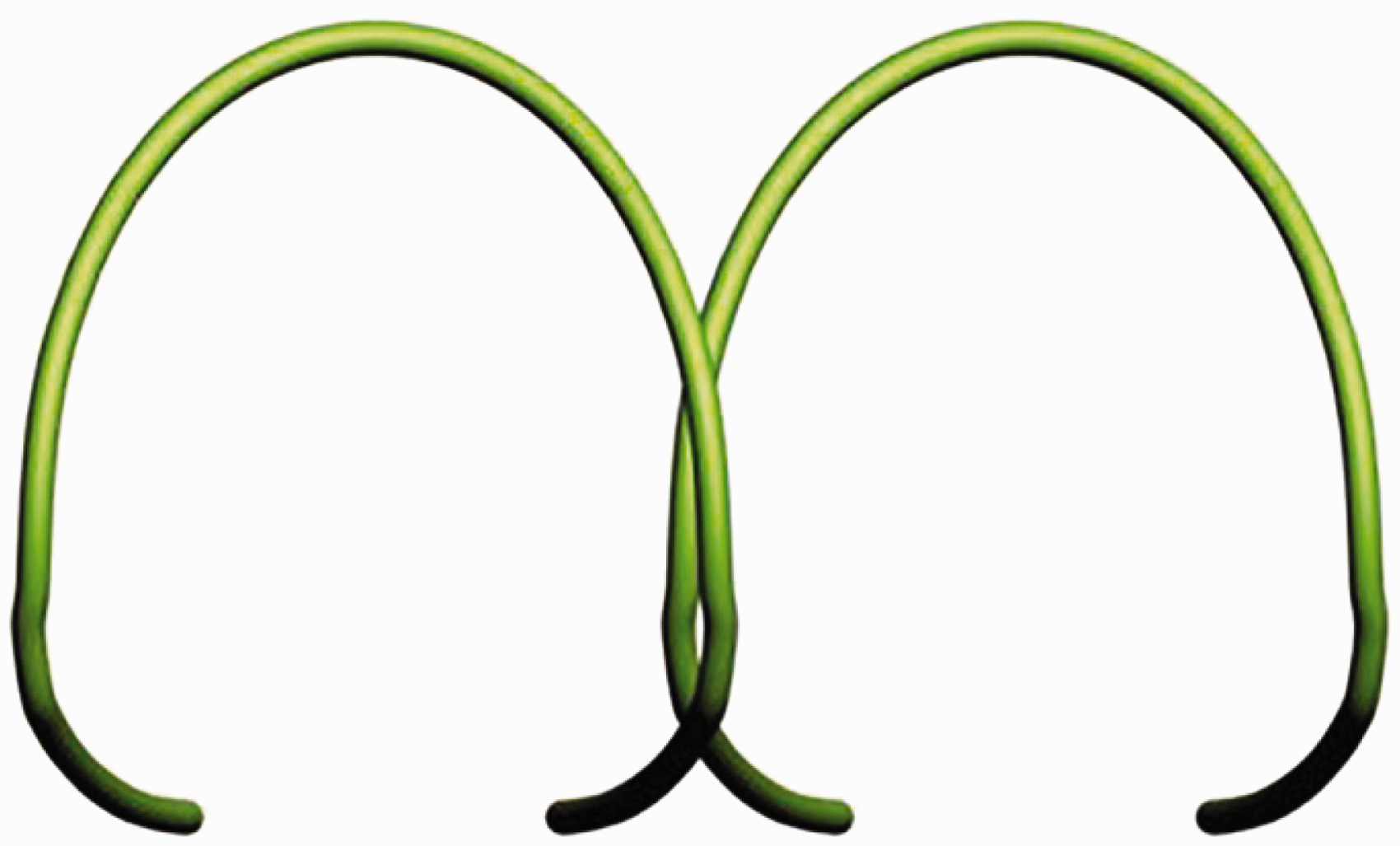
At the first stage, the spacer yarn between the front and back fabric was modeled by wrapping the yarn on a straight cylinder as in Figure 9(a). The model of the spacer fabric with this assumption was drawn as in Figure 12(a). This model did not satisfy our observations of the real spacer fabrics; therefore, we bent the straight cylinder into a torus shape (as in Figure 9(b)) and obtained the shape given in Figure 12(b) for the present model. The curves of the spacer yarns, given in Figure 12(b), were the same as we observed on the real fabrics. Therefore, in the present model shapes given in Figure 12(b) are used for the modeling of the spacer yarn curves.
Modeling of the spacer yarn: (a) modeling with wrapping the yarn on a straight cylinder and (b) modeling with wrapping the yarn on a torus. Crossing of two cylinders with equal radii in three-dimensional space to obtain a continuous wrapping curve.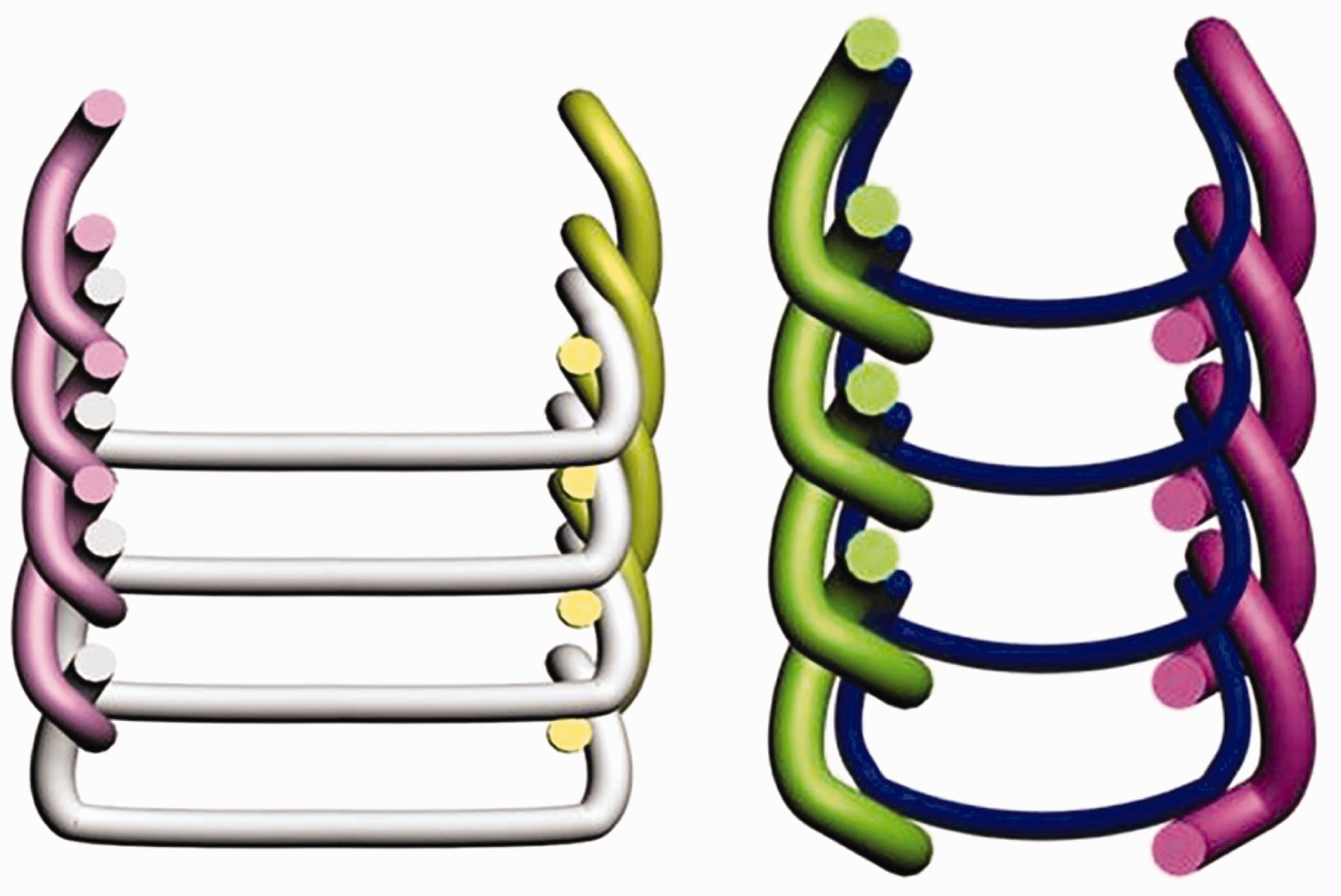
Conclusion
Nowadays, weft-knitted spacer fabrics are used for creating various functional materials, such as materials with a cushioning effect, liquid absorbent materials, materials that have thermal insulation and/or noise reduction, conductive materials, sport-wear with different yarn properties for front and back layers of spacer fabrics, electromagnetic shielding materials, lightweight cement composite materials, liquid cooling materials with inserted tubes in between the layers, etc. Since these applications are costly, some software package programs have been developed to check whether the cultivated technical function of the material is suitable for the related applications. These software package programs, then, use geometrical models of the materials as input data.
In this study, geometrical models for two commonly used weft-knitted spacer fabrics are given based on Kurbak and his colleague’s models7–15 to be used in the above given software package programs or in theoretical calculations of the above given functions. One of the created models is for spacer fabrics obtained by rib gaiting and the other created model is for spacer fabrics obtained by interlock gaiting of the machine. The models created were drawn to scale using the 3DS-MAX computer graphical program. It is seen that the shapes obtained by the models are very similar to the shapes observed on real fabrics.
Footnotes
Acknowledgement
The author would like to thank Tuba Alpyıldız, Mustafa Değirmencioğlu and Neyra Nam for their contributions to the initial drawings.
Declaration of conflicting interests
The author declared no potential conflicts of interest with respect to the research, authorship and/or publication of this article.
Funding
The author received no financial support for the research, authorship and/or publication of this article.