
Abstract
Polyacrylonitrile (PAN) fiber coated with photocatalyst titanium dioxide (P25) was successfully fabricated by a dip coating process using dimethyl sulfoxide (DMSO)/ethanol (EtOH) as co-dispersion solvent. Photocatalytic performance of P25-coated PAN fibers was evaluated by degrading a model dye rhodamine B (RhB) in aqueous solution under ultraviolet (UV) light irradiation. The preparation parameters of P25-coated PAN fibers were optimized by an orthogonal design, and were found to be a P25 concentration of 0.05 g/L, a ratio of 85/15 (v/v) DMSO/EtOH, and a take-up speed of 0.5 m/min. A possible mechanism of co-dispersion solvent dip coating was proposed based on Hansen solubility parameters’ theory. The P25-coated PAN fibers prepared at the optimum conditions had high dye removal efficiency. They also showed an excellent cycling performance for dye removal of up to 99% recovery over several cycles. The coating process has little impact on both the fiber strength and the breaking strength. The breaking strength of P25-coated PAN fibers was maintained even after several cycles. This study provides an easy-to-scale-up method for preparing P25-coated PAN fibers. The obtained P25-coated PAN fibers show great potential as a low-cost, easy handling, and recyclable photocatalyst for dye effluent treatment.
Large quantities of highly colored effluent are produced in the textile industry. It has been reported that of about one million tons of dyes produced annually worldwide, about 10%–15% are disposed of in effluent through incomplete exhaustion and washing processes.1,2 Their releases causes serious damage to the aquatic environment due to high toxicity, low biodegradation, and potential carcinogenicity. 3 Several decolorization technologies, including biological degradation, 4 adsorbents, 5 nanofiltration membranes, 6 and photocatalysts have been employed for dye effluent treatment. After a prototype photocatalyst was reported by Fujishima and Tadashi,7,8 the photocatalyst TiO2 has aroused intensive interest over the past decades due to its high photocatalytic activity, thermal and chemical stability, and low cost. The activation of TiO2 for photocatalytic reactions can be achieved by irradiation with an illumination equal to or greater than its band gap. 9 Excitation of the electron from the valence band to the conduction band will occur once TiO2 absorbs light with energy that matches its band gap. As a result of electron excitement, photo-generated electrons and holes react with water or oxygen, and highly reactive oxygen species (e.g. OH√, O2√−) are generated, which are able to degrade a wide range of organics into readily biodegradable compounds, eventually mineralizing them to carbon dioxide and water. 10 Many studies have focused on the efficient elimination of the organic pollutants by using photocatalysts. However, most of the conventional photocatalysts cannot be recovered effectively. It is important to develop a new reusable photocatalyst with high photocatalytic activity for dye wastewater management.
One effective method to obtain recoverable photocatalysts is to immobilize the photocatalysts on carriers for easy separation from solution. 11 Many efforts have been devoted to coating fibers/fabrics with photocatalysts.12–14 Currently, photocatalysts can be successfully immobilized on fibers/fabrics through methods including sol–gel,15,16 spray coating, 17 plasma, 18 pad–dry-cure, 19 and dip-coating. 20 Among these methods, dip coating is a representative low-cost and simple process, which can be carried out under mild conditions. However, the main drawback of dip coating is a lack of the sufficient adhesion. Until now, it has remained a challenge to achieve a uniform and stable coating of photocatalyst nanoparticles on textile using an easy-scale-up method. 21
In this study, P25-coated PAN fibers were fabricated using dimethylsulfoxide (DMSO)/ethanol (EtOH) as a co-dispersion solvent by a facile dip coating method. PAN fiber was chosen as a matrix due to its remarkable resistance against UV degradation.22,23 The co-dispersion solvent can partly dissolve and swell the PAN, and at the same time facilitate the anchoring of P25 nanoparticles onto the PAN fiber surface during the dip coating process. The optimal coating conditions were determined by the photocatalytic performance of the obtained P25-coated fibers. The surface morphologies, microstructure, mechanical properties, and re-use performance of the P25-coated PAN fibers were also investigated.
Materials
Titanium oxide nanoparticles (commercial P25, 25 wt% rutile and 75 wt% anatase, ∼21 nm, Degussa Co.); rhodamine B (RhB, 98%, Sigma–Aldrich); PAN fibers (filament, AN component > 90%, 150D/60F) were acquired from Changshu Xiangying Special Fiber Co., Ltd., Jiangsu, China. Dimethylsulfoxide (DMSO, analytical reagent grade) and ethanol (EtOH, analytical reagent grade) were purchased from Chem-Supply Pty Ltd, Gillman, SA, Australia. All the chemicals were used as received.
Experimental
Solvent preparation
A solvent mixture was carefully screened as the co-dispersion solvent for P25 dispersion and polymer solvation. Briefly, a designated amount of P25 was dispersed into a mixture of DMSO and EtOH at different volume ratios (85/15, 80/20, 75/25; v/v) by ultra-sonication for 15 min (Omni Sonic Ruptor 400 W Ultrasonic Homogenizer, Kennesaw, GA, US). Ultrasound was operated at 50% pulsar mode. P25 dispersion was prepared at the concentrations of 0.01, 0.03, and 0.05 g/L, respectively.
Co-dispersion solvent dip coating
The PAN filaments were un-wound from a bobbin and dipped in the P25 dispersion bath. During the coating process, P25 was deposited on the surface of the PAN fiber due to solvation and diffusion. The filaments were then drawn into a coagulation bath at constant speeds of 1, 2, and 5 m/min, respectively. After removal of the residual solvent and polymer solidification, P25 nanoparticles were anchored onto the PAN fibers. P25-coated PAN fibers were obtained after being washed with deionized water and dried in a vacuum oven for 24 h at 60℃. All the procedures were repeated for preparing the twice coated fibers. A schematic diagram of the preparation process is shown in Figure 1.
Schematic diagram of co-dispersion solvent dip coating process.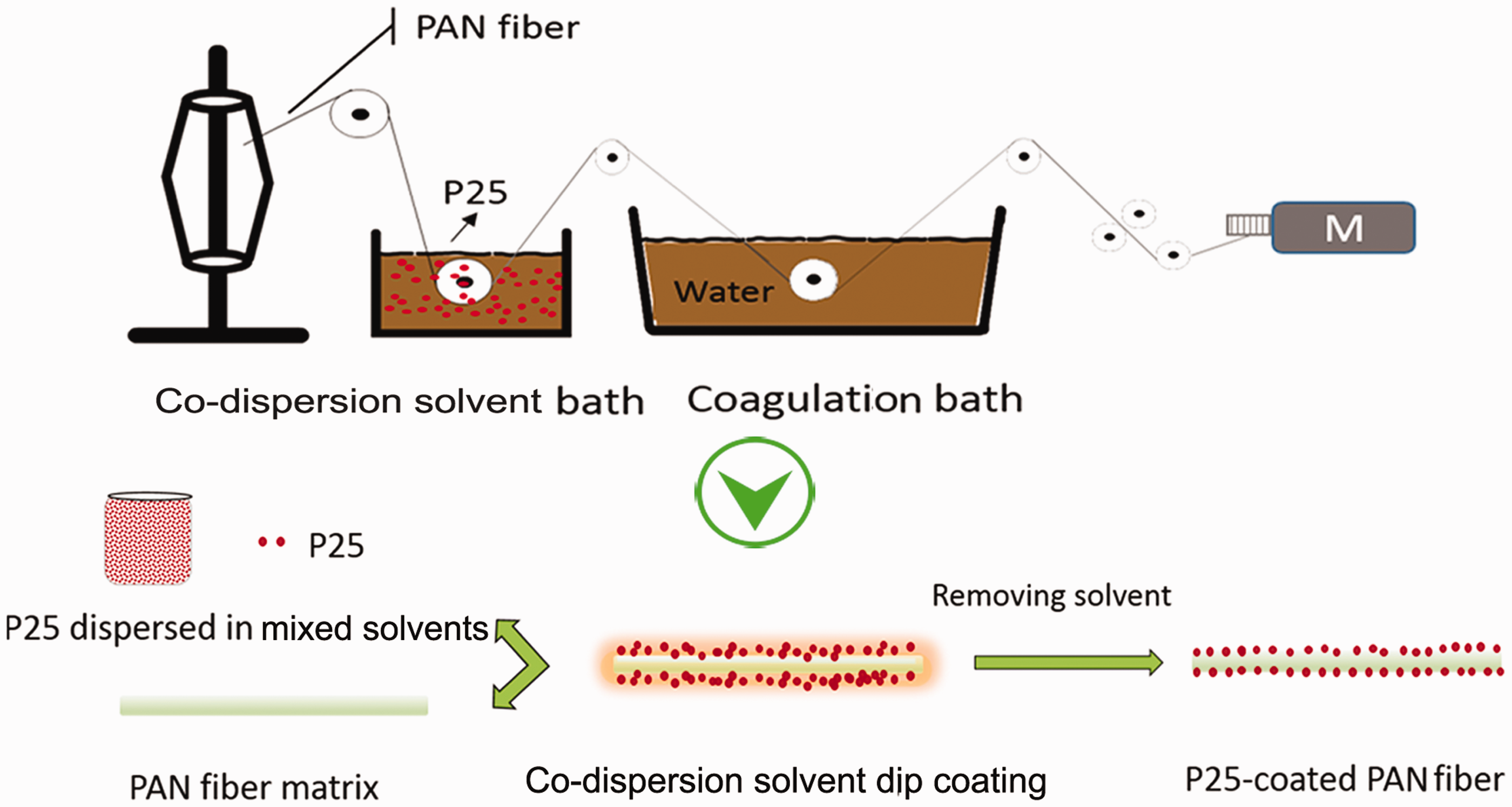
Optimization of dip coating conditions
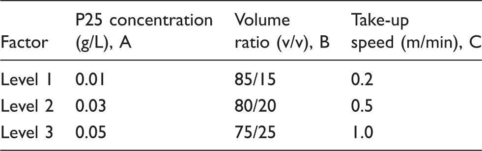
Three factors and three levels for each variable
The optimal coating conditions were determined according to dye removal efficiency and the durability of P25-coated PAN fiber. P25-coated PAN fiber prepared at the optimum conditions based on this orthogonal design was used for further study, which was labeled as sample #10.
Characterization
The morphologies and structure of P25-coated PAN fiber were investigated by a scanning electron microscope (SEM) on a Supra 55VP (Zeiss, Germany) operated at an acceleration voltage of 5.0 kV and an atomic force microscope (AFM) in Scanasyst-air peak force tapping mode. A silicon tip on a nitride lever with a spring constant of 0.4 N/m and a scan rate of 4 Hz was used to examine the samples. Energy dispersive X-ray (EDX, Oxford Instruments, UK) spectra was also obtained. Fourier transform infrared spectroscopy (FTIR) spectra were recorded on a Bruker VERTEX 70 instrument (Bruker Optics GmbH, Germany) using the KBr method. 24 Thermal degradation spectra were collected by a thermogravimetric analyzer (TGA) (Netzsch Inc., Germany) under nitrogen, with a temperature ramp rate of 10℃/min. Wide-angle X-ray diffraction (WXRD) measurements were performed by Bruker AXS D8 DISCOVER with GADDS (Madison, USA), and Cu-Kα radiation (λ = 1.5418 Å) was employed.
Photocatalytic activity test
RhB was used as a model molecule to evaluate the photocatalytic activity of P25-coated PAN fibers. The experiments were carried out according to the following procedure.
10 mg of P25-coated PAN fibers were placed in 10 mL of RhB aqueous solution with a concentration of 6 ppm in a 100 mL quartz beaker. The suspension was stirred in the dark for 1 h to ensure the establishment of an adsorption and desorption equilibrium of RhB dye molecules on the surface of the catalysts. Subsequently the suspension was irradiated with UV light under vigorous stirring. After reaction for 1 h, the residual solution was extracted and then measured with a Varian Cary 5000 UV-vis spectrophotometer (Varian Co., US). The characteristic optical absorption peak of RhB at 554 nm was employed to monitor the photocatalytic degradation process. The P25-coated PAN fibers were re-used to remove dye by being immersed in another RhB solution (6 ppm, 10 mL). The residual suspension after each cycle was independently tested. Removal efficiency of RhB was determined by equation (1)

Physical properties
Individual uncoated and P25-coated PAN fibers were randomly and gently withdrawn after they had been conditioned for more than 24 h at 20 ± 2℃ and 65 ± 2% relative humidity. To investigate the effect of UV irradiation on the mechanical properties of the fibers, P25-coated fibers were subjected to 5 h irradiation and then were conditioned as above for the stress–strain test. Then the diameter of each single fiber was scanned and measured at 5 mm intervals along its length on the single fiber analyzer (SIFAN). The pre-tension was set at 0.2 cN to keep the fiber straight. At least 10 single fibers were measured for each sample.
Single fiber strength is a vital index for its application. Tensile properties of single fibers were tested on the SIFAN instrument with a clip speed of 500 mm/min and a gauge length of 25 mm. All the tests were conducted under standard environmental conditions (20 ± 2℃ and 65 ± 2% RH). The tensile values obtained when fibers broke at or near the jaws were not counted. All the sample tests were replicated 50 times.
Results and discussion
Optimal fiber coating conditions
The results of L9 (3) 3 orthogonal test design
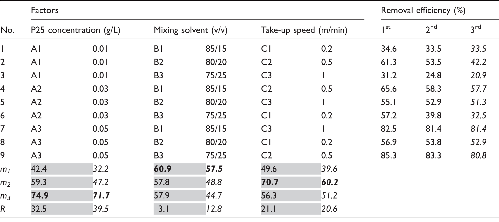
mi (i = 1,2,3) stands for the mean value at the same level, e.g., m1 = (34.6 + 61.3 + 31.2)/3 at factor A1.
R is the range of the orthogonal experiment, namely the biggest difference among each factor with the different levels of the experimental results, e.g., R = max(42.4, 59.3, 74.9)-min(42.4, 59.3, 74.9) = 32.5 at factor A; the two adjacent columns of mi and R represent removal efficiency with 1st (grey background) and 3rd (blank background) cycle. The optimum level and factor is highlighted as bold.
The three different levels of three variables were chosen within a rational range for the following reasons. (1) The concentrations of P25 nanoparticles have an effect on the contact between P25 nanoparticles and fibers, as well as the stability of the P25 suspension. For example, a concentration of lower than 0.01 g/L would not provide enough contacts for dense coating. However, a concentration higher than 0.05 g/L resulted in a non-stable dispersion. (2) The solvent composition of the DMSO/EtOH mixture has an impact on the coating fastness and fiber strength, and could even give rise to sticky fibers. A high concentration of DMSO would be favorable for coating fastness, due to stronger solvation. However, this goes along with geometrical shape changes and binding between fibers (see Appendix 1). (3) Take-up speed can affect the fiber straightness and immersion coating time. Fibers can hardly finish a free coating process at a high take-up speed. Meanwhile, a low take-up speed can result in extreme swelling/solvation due to the long coating time, leading to enhanced coating fastness along with decreased fiber strength.
As shown in Table 2, about 81% dye removal was achieved in both test 7 and test 9 after three cycles use. The m and R values were calculated and are listed in Table 2 based on orthogonal experiment and range analysis. R decreases in the order of P25 concentration > take-up speed > solvent composition. This suggests that the influence on dye removal efficiency decreases in the order of P25 concentration > take-up speed > solvent composition. In other words, P25 concentration plays the most important role in achieving high dye removal efficiency of P25-coated PAN fiber. The combination of the levels with the highest m value for each variable gives rise to the optimum conditions. It can be seen from Table 2 (highlighted in
Characterization of P25-coated PAN fibers
SEM images of the PAN fibers before and after coating are shown in Figure 2. The original PAN fiber (Figure 2(a)) shows a smooth surface with some grooves. After dip coating process, the surface of PAN fibers become coarse, which reveals the existence of P25 nanoparticles on the PAN fiber matrix (Figure 2(b)). The morphologies of P25 nanoparticles are preserved in natural status after they are deposited on the fiber surface, with nano-size particles inlaying into the PAN fiber. This dense and even P25 coating was still maintained after five times re-use of the fibers, which indicates the good fastness of P25 coating on the PAN fibers (Figure 2(c)).
SEM images: (a1) PAN fiber, (b1) P25-coated fiber, (c1) P25-coated fiber after 5 cycle use. High magnification of fibers are shown in (a2), (b2), and (c2).
The morphologies of the samples before and after coating were also determined by AFM. As shown in Figure 3, a smooth surface with some grooves was observed on the original PAN fiber (Figure 3(a)), which is consistent with the SEM result. Close examination of the AFM images (Figure 3(b)) reveals that P25 was densely coated on the surface of the PAN fiber under the optimized conditions. Most of the P25 remained spherical on the PAN fiber. Some coarse microstructures were also found on the surface, which may be caused by particle aggregation. Both the SEM and AFM results suggest effective coating of P25 nanoparticles on the PAN fiber. The roughness (Rq) value labeled in Figure 3 shows that P25-coated fiber (Rq = 234 nm) is much rougher than the pristine PAN fiber (Rq = 167 nm). According to the Wenzel mode, for a hydrophilic solid substrate, the hydrophilicity will be enhanced by surface roughness.
25
This obtained rough surface would facilitate P25-coated fiber for dye removal application.
2D and 3D 5 µm, and 3D 500 nm AFM scans for AFM topography images: (a) PAN fiber, (b) #10 P25-coated fiber. Roughness (Rq) is also marked.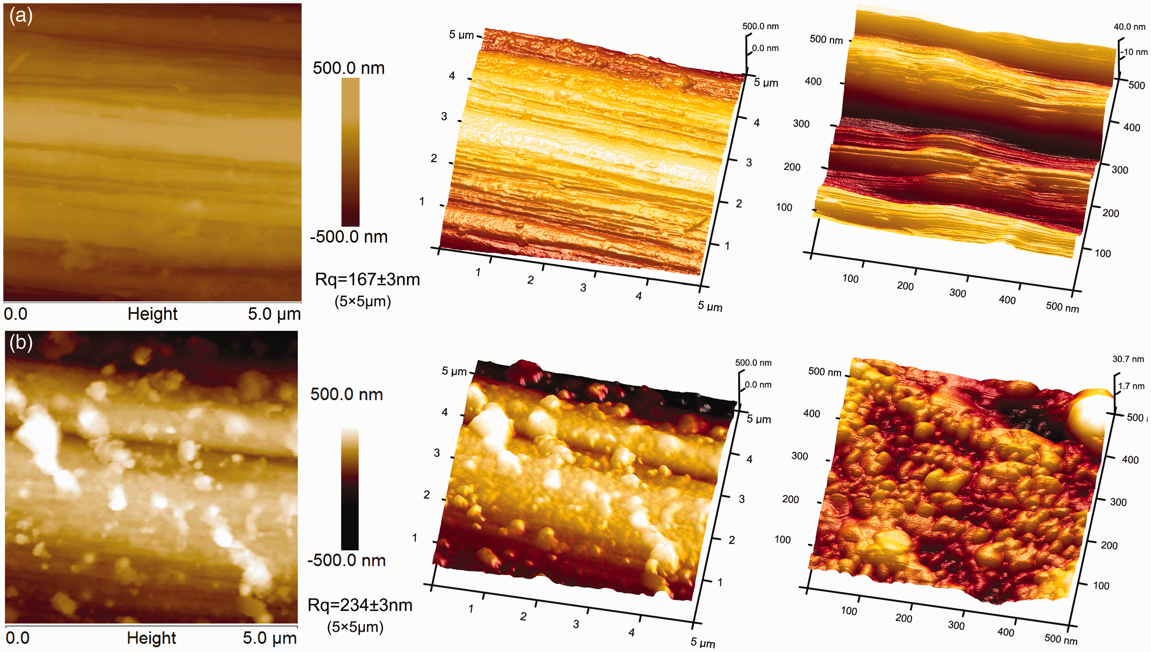
The P25 coating was further characterized by EDX and FTIR. Typical EDX images (Figure 4) were used to study the surface composition. For PAN fiber, only elements C, O and N are observed (Figure 4(a)). Element O might come from the co-monomers of PAN polymerization. For the P25-coated PAN fibers, Ti and relative O-rich elements are simultaneously detected, which further confirms the successfully coating of P25 (Figure 4(b)).
EDX results for (a) PAN fiber, (b) P25-coated fiber.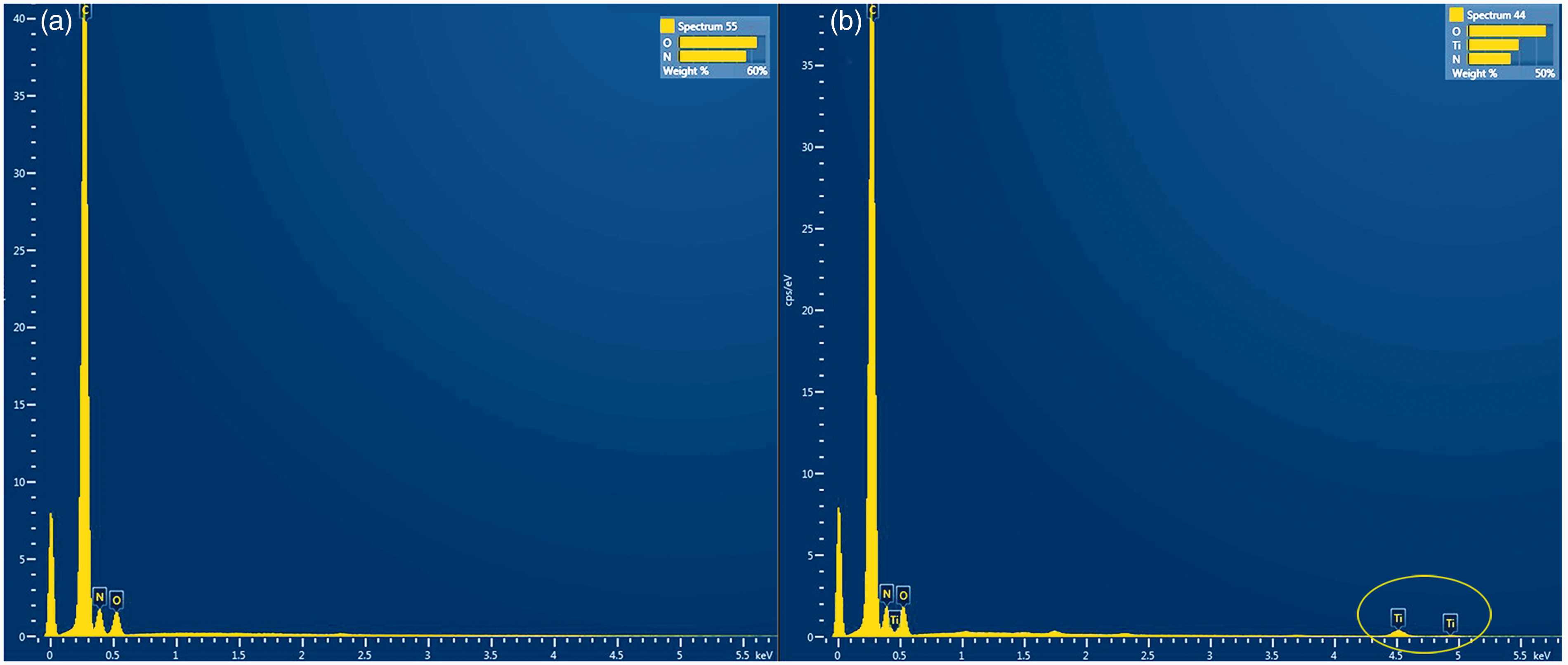
Figure 5 shows the results of FTIR spectra of the uncoated PAN fibers, P25 nanoparticles, and P25-coated PAN fiber. The characterization band for P25 nanoparticles appears at around 690 cm−1, which corresponds to the vibration of Ti–O–Ti bonds
26
. For PAN fibers, the absorption peak appears at about 2245 cm−1 which is related to presence nitrile (C≡N) bond, indicating the existence of nitrile group in the PAN fiber. The absorption peaks at 2939, 2870, and 1376 cm−1 are related to C–H bonds in CH, CH2, and CH3. The absorption peaks in the range 1743–1450 cm−1 are related to C=O or C–O bonds, which may be attributed to the presence of co-monomers like methyl acrylate. After coating P25 onto PAN fiber, 690 cm−1 for the vibration of Ti–O-Ti bonds are also observed in the FTIR spectrum of P25-coated PAN fibers, which indicates the presence of TiO2 in the P25-coated PAN fiber.
FTIR spectra of the uncoated PAN fibers, P25, and P25-coated PAN fibers.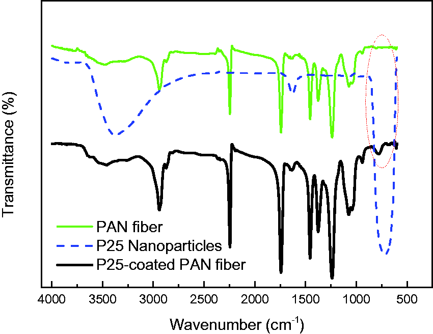
To calculate the amount of P25 loaded on the surface of the PAN fiber, thermogravimetric analysis (TGA) was performed on both the uncoated PAN fibers and P25-coated PAN fibers under N2 atmosphere. The loading level of P25 was determined based on the residual weight of the fibers. As shown in Figure 6, for the P25-coated PAN fiber, 42.9 wt% residual weight is found after heating up to 800℃. This is compared to 37.2 wt% residual weight found for the original PAN fiber. This indicates the loading level of P25 on the PAN fiber was 5.7%.
TGA curves of the uncoated PAN fibers and P25-coated PAN fibers.
Photocatalytic activity
The photodegradation of RhB was further carried out to evaluate the photocatalytic performance of P25-coated PAN fibers under UV irradiation.
Typical UV-vis adsorption spectra of RhB solution before and after degradation in the presence of the P25-coated fibers at 1 h intervals during 3 h UV irradiation. Insets are images of the RhB solution before and after degradation.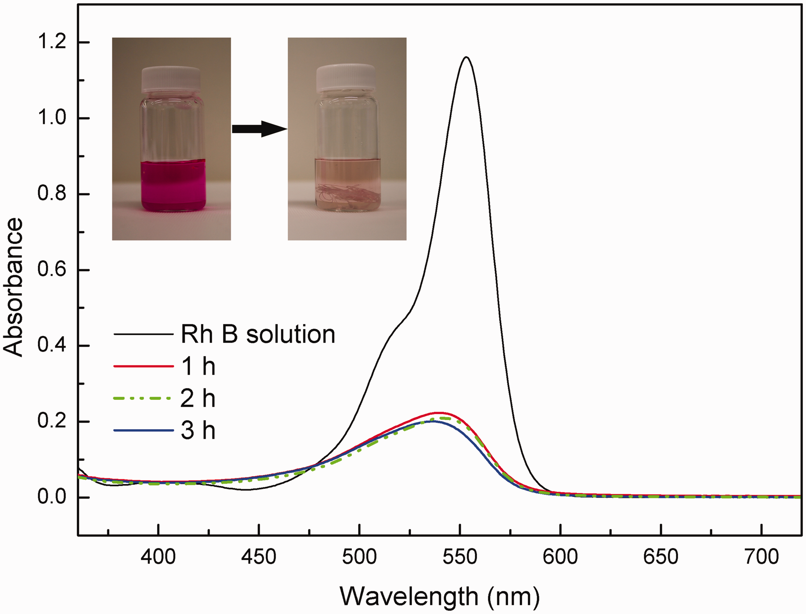
Figure 7 shows absorbance of original RhB solution and the time-dependent absorption spectra of RhB solution under UV irradiation. Without photocatalyst, the degradation of RhB is negligible under UV irradiation. 27 The degradation of RhB was observed in the presence of the P25-coated PAN fibers and was almost completed within 1 h.
The reusability of photocatalysts is an important property required for industrial applications. Therefore, the recycling performance of the P25-coated PAN fibers was investigated by performing several cycles of dye removal under UV irradiation. As shown in Figure 8, 83% dye removal efficiency was achieved for the P25-coated PAN fiber prepared under optimum conditions which were obtained from the orthogonal design. This dye removal efficiency further confirms the optimal conditions for fiber coating as 0.05 g/L, 85/15 v/v, and 0.5 m/min. 83% of RhB was removed after 1 h irradiation in the first cycle, and the P25-coated PAN fibers could maintain the degradation efficiency to 81% after five cycles. The SEM image of P25-coated PAN fiber after five cycles shows P25 distributed uniformly on the surface of the PAN fiber. This dense and uniform coating of P25 on the PAN fiber can provide highly effective photodegradation of dye molecules, which facilitates the excellent cycling performance of P25-coated PAN fiber. The excellent recycling properties of P25-coated PAN fiber further confirmed the sufficient fastness of P25 coating on the surface of PAN fibers.
The durability of the P25-coated PAN fibers for dye removal after several cycles.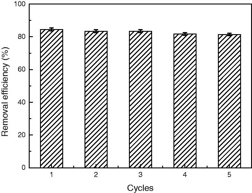
A second coating was applied on PAN fiber according to the optimal coating conditions. The twice-coated fibers obtained were also used for dye removal to verify whether a higher loading of P25 could be achieved by repeated coating, with a higher photocatalytic activity for dye removal. Figure 9 shows the dye removal efficiency of the P25-coated PAN fiber after once- and twice-coating. Negligible dye removal improvement was observed after twice-coating in the first cycle. P25-coated PAN fiber after twice-coating shows the same dye removal efficiency as the fiber from once-coating after five cycles. This result may be caused by the P25 loaded in the second coating being removed during washing due to insufficient anchoring. Hence once-coated of P25 on PAN is sufficient to provide high efficiency for dye removal.
The durability of the P25-coated fibers with different coating times for dye removal.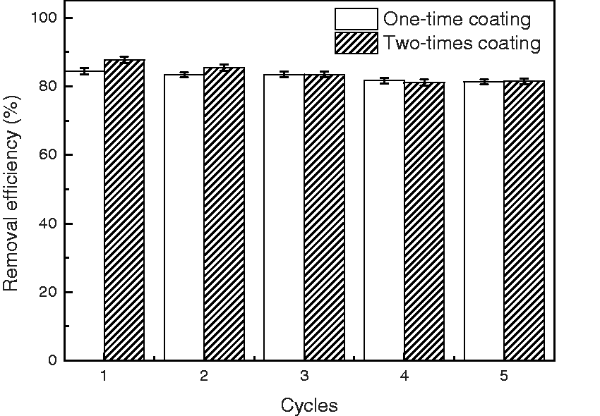
Tensile strength and crystallite characterization
Physical parameters of PAN fiber, P25-coated PAN fiber before and after UV treatment
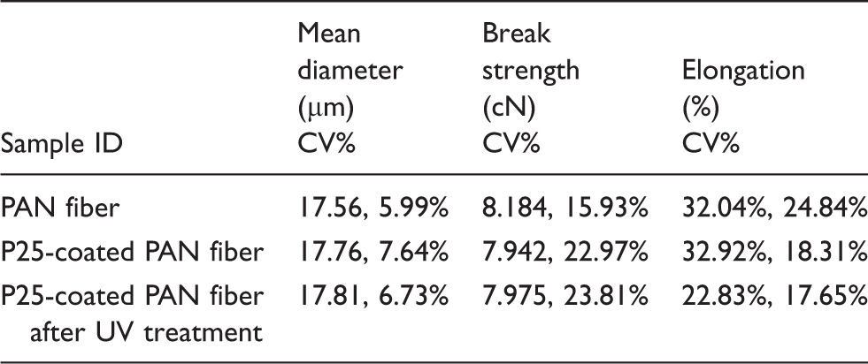
Figure 10 shows the stress–strain curves of PAN fiber, P25-coated fiber before and after UV treatment. All the tested fibers show high strength combined with high breaking elongation, which reach the commercial rank.
30
The lower part of the stress–strain curves can be modified to eliminating the negative effect of pre-tension.
31
After the creep stage, there is commonly a plastic region, showing a yield point in the range of 2–3 cN/dtex. Thereafter, a second drawing stage is observed, until moderately high strength fracture. Although the tendencies in the ascending region corresponding to initial modulus are similar, the P25-coated fiber after UV treatment has a relatively lower elongation than PAN fiber and P25-coated PAN fibers before UV treatment.
Typical stress–stain curves for PAN fiber and P25-coated PAN fiber before and after UV treatment.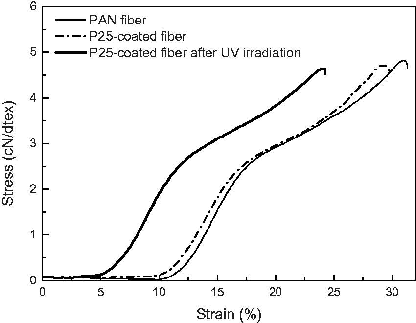
Figure 11 shows the WXRD patterns of PAN fiber, P25-coated fiber, and P25-coated fiber after UV irradiation. It is can be seen that the strongest characteristic crystalline peak of PAN fibers appears at around 2θ = 17°, which can be indexed to the (100) plane of a hexagonal structure.
32
For both PAN fiber and P25-coated PAN fiber, the peak areas relating to the crystallinity of the PAN are almost the same. This indicates that the crystalline structure of the PAN fiber is maintained after the dip-coating process. A strong characteristic crystalline peak at 2θ = 25.5°was observed for P25-coated fiber after UV irradiation, which is assigned to TiO2.
33
The weak peak at 2θ = 17° reduces greatly, which indicates the crystalline structure of PAN has been partially destroyed, resulting in the PAN macromolecules being unable to reform their regular arrangement. This may lead to a lower elongation of the P25-coated fiber after UV treatment compared to PAN fiber and P25-coated PAN fibers before UV treatment.
WXRD patterns of PAN fiber, P25-coated fiber before and after UV irradiation (inset: P25 powder).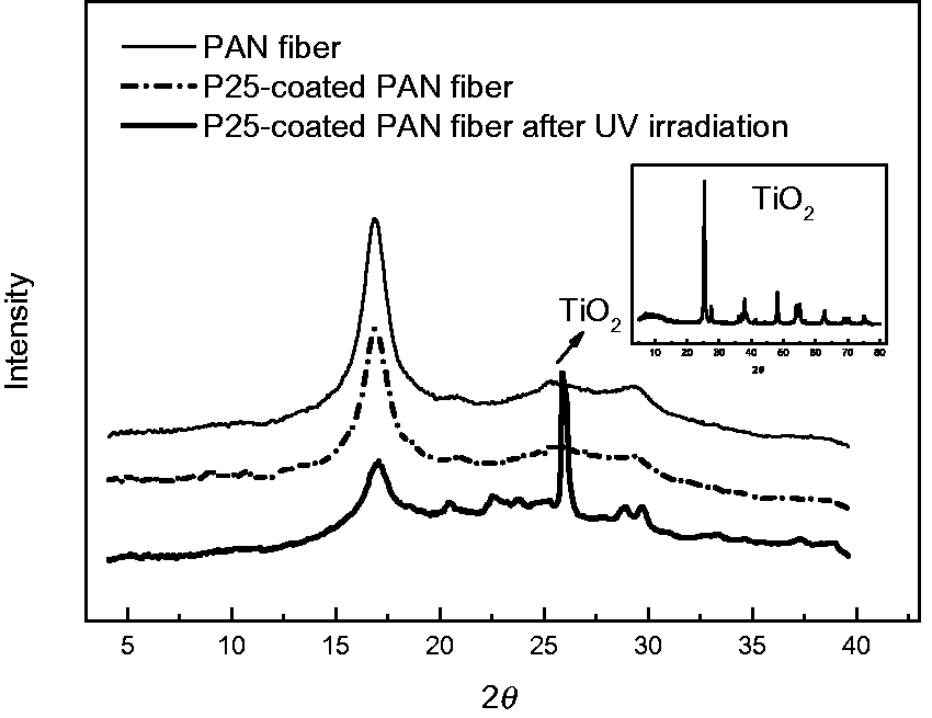
Co-dispersion solvent dip coating mechanism
P25 was coated onto PAN fibers during the solvation and solidification process. In the DMSO/EtOH solution, there is movement of the polymer chain segment on the surface of the PAN fibers, and at the same time P25 nanoparticles diffuse into the surface of the PAN fibers. Then the PAN fibers go through a coagulation bath, where macromolecular shrinkage occurs and some P25 nanoparticles are loaded and immobilized on the surface of the PAN fiber. This process can be further explained by polymer–solvent interaction theory, based on the solubility parameters of PAN and the DMSO/EtOH solution. Hansen et al. introduced a three-component solubility parameter to account for the dispersive forces, the polar interactions, and hydrogen bonding, as described by equation (2)
34

For the mixed solvents, the δaverage value can be estimated from equation (3)
35

Each of the three component solubility parameter (δi) can be calculated by equation (4)
36


Solubility parameters of DMSO/EtOH mixtures at different volume ratios
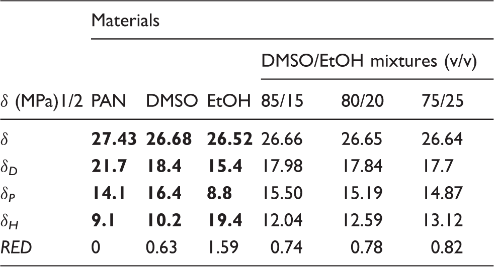
The data in bold are from the literature. 34
The ratio between Ra and Ro (radius of the solubility sphere) is called the relative energy difference (RED) (see equation (6))
34

As Hansen mentions, 34 the interaction between polymer and solvent depends on their solubility parameters relative to each other, and the RED number easily quantifies this interaction. The smaller the RED number, the higher the affinity between the solvent and the PAN fiber. Since Ro of PAN = 10.9 (MPa)1/2, RED (PAN-DMSO) was calculated to be 0.63, and RED (PAN-EtOH) was 1.59. Therefore, DMSO was found to have good affinity and be a good solvent for PAN compared to EtOH, which is consistent with the literature. 38
When the solvent has a small RED, the polymer may be dissolved in the solvent, which may result in fibers sticking to each other after the dip-coating process. To obtain P25 coat on single filaments, the chosen solvent in this case should have a reasonable big RED number, to assure the coating’s stability. 39 DMSO/EtOH mixtures are the right solvent following our screening.
Conclusions
P25 nanoparticles were successfully immobilized on PAN fibers by a co-dispersion dip coating method, which is an easy-scale-up fabrication process. The optimized solvent mixture can disperse P25 nanoparticles and provide suitable solubility for PAN fiber at the same time. The optimum coating condition was found to be a P25 concentration of 0.05 g/L, solvent composition with a ratio of 85/15 (v/v), and take-up speed of 1 m/min. The obtained P25-coated PAN fibers showed a good performance for dye removal and an excellent durability, even after five cycles. PAN fibers were proved to be a good carrier for P25 nanoparticles in dye removal. Moreover, the tensile strength of the P25-coated fibers remained almost the same after several cycles of use under UV irradiation. A possible mechanism of co-dispersion solvent dip coating was proposed based on Hansen’s solubility parameters theory. These P25-coated PAN fibers provide ease of handling and will broaden the use of photocatalysts for dye wastewater management in environmental remediation.
Footnotes
Conflict of interest
None declared.
Funding
We gratefully acknowledge the support from the following sponsors: MoE Innovation Team Project in Biological Fibres Advanced Textile Processing and Clean Production, National Basic Research Program of China (grant number 2012CB722706), National Natural Science Foundation of China (grant number 51403154), and Zhejiang Provincial Top Key Academic Discipline of Chemical Engineering and Technology, Zhejiang Sci-Tech University (grant number YR2015004).