
Abstract
Highly electrical conductive fibers have received significant attention because of their potential to be utilized for wearable technology. Conductive fibers have already been developed by many research groups using metal and carbon nanotubes (CNT); however, productivity is limited. Conductive fibers composed of conductive additives embedded in a polymer matrix were fabricated by a melt-spinning process. This enables the scaling-up of production and gives high mechanical strength compared to fibers prepared by other processes. Silver (Ag) was selected for the conductive material, and embedded in polypropylene (PP) fiber. However, the melt-spinning process has an inherently lower filler content threshold; therefore, it was difficult to fabricate with sufficient silver for the required electrical properties. CNT forests were introduced to make up for this shortcoming, and they could serve as a conductive bridge between unconnected Ag. The CNT percolation effect confirmed that non-conductive Ag/PP increases electrical conductivity after CNTs were added. It was determined that 80 nm Ag (46 wt%) and single wall CNT (4 wt%) embedded PP composite fiber (Ag80/SW_46/4) was the optimum fiber; with a thickness of less than 100 µm its electrical conductivity was 4.1–7.2 × 10⁻² S/cm. Conductive fabric was fabricated using our composite fiber, and it had higher electrical conductivity than that of a single fiber because multi-filaments induced lower electrical resistance. Although the electrical value attained does not approach a satisfactory goal, it is thought that this fiber has a potential to be applicable for wearable technology.
With wearable technology becoming of increasing interest, fiber has come back under scrutiny because it shows high flexibility and benefits for knitting and sewing processes.1,2 To realize smart textiles successfully, it is essential to be able to prepare fiber that is highly electro-conductive. The conductive fiber itself, acting as a conductive wire, has the possibility to change innovative devices such as sensors, actuators, electromagnetic interference (EMI) shielding, and electrostatics.3–6 Further, it enables the use of electrical components such as supercapacitors, organic light emitting diodes, photovoltaics, transistors, and batteries. Such wearable electronics could find a wide range of applications for human convenience and health, such as biomedical monitoring systems, communication tools, and personal security.7–9 For this reason, much research proceeds briskly to make highly electroconductive fiber, while several materials have been proposed as fiber components.10–12 To be specific, polymer is lightweight and the only material that recovers after bending, stretching, and wrinkling; therefore, it should be used as a base material for a wearable unit. However, polymers are generally known to be non-conductive insulators. Some conductive polymers such as poly(aniline), poly(3,4-ethylene dioxythiophene), and poly(pyrrole), show a high electrical conductivity of over 102 S/cm.13–16 It is impossible to make fibers take a shape themselves; however, they show very low conductivity when combined with other polymers. Therefore, other materials that are to be matched with the polymer must have appropriate electrical properties. In this field, various attempts have been made to use metals such as Cu, Au, Pt, and Ag in polymer-based fiber for their high electrical conductivities.17,18 It was considered that Ag was the most appropriate metal because of its high electrical conductivity and oxidation stability in atmospheric air. Pt and Au also show the same benefits, however they make the fiber very costly and heavy. Successful results have been reported for polymer/Ag produced by solution spinning, 19 metal coating, 20 electrospinning, 21 and bubbfil spinning 22 processes having a high electrical conductivity of over 103 to 104 S/cm. These are powerful methods for positioning and dispersing metals in a polymer matrix, although they are unsuitable for mass production because of their complicated, high cost, and time-consuming processes. The melt-spinning process is rarely tried because the mixing ratio, regulation, proper dispersion, and the elongation of as-spun fibers are difficult to control. For this reason, this process has hardly been demonstrated to fabricate highly conductive fibers. Nevertheless, it is absolutely necessary for scaling-up production because it facilitates a fast and cost-effective process. In addition, the fiber fabricated by melt-spinning possesses high mechanical strength compared to that prepared by other processes. In this regard, developing a method to fabricate highly electro-conductive composite fiber possessing a combination of high amounts of additives, high capacitance, and a simple melt-spinning process was a significant challenge for our research.
Conductive fiber preparation
Much of the literature has announced ways to improve the electrical properties of fibers. Of the types of conductive fillers to be connected to the fiber matrix, many should be embedded with at least 52.3 vol% (simple cubic (SC), minimum packing efficiency) to 74.1 vol% (face centered efficiency (FCC), maximum packing efficiency). In the case of pure Ag, the volume packing fractions were converted to 92.0 wt% (SC) and 96.8 wt% (FCC) of the weight packing fractions.
There are two distinct routes for manufacturing highly electro-conductive composite fibers. One route employs the solution-spinning process, wherein excessive Ag is directly dispersed into a spinnable dope with an adaptable solvent, extruded through a nozzle, and coagulated. This approach allows the composite fiber to have high electrical conductivity (over 500 S/cm, Ag 95 wt%/PVDF (Polyvinylidene fluoride) 5 wt%, confirmed by our research). Cross-sectional images of the fibers are shown in Figure 1. The highly packed composite fibers, however, have poor orientation properties and include impurities within their structure. Furthermore, the fiber having Ag amounts of over 50 vol% were impossible to fabricate by a melt-spinning process as described above. The alternative fiber structuring concept forms an electron “bridge” by using a one-dimensional filler. Anisotropic fillers such as metal nanowire (NW) are mainly used because they exhibit a large aspect ratio and offer the opportunity to connect electron paths between metal particles regardless of their low concentration. Metal NW embedded composite fibers are verified to exhibit superior electrical conductivity in the initial and extended states due to the high wt% of the metal particles, acting as metal NW electrical bridges.
23
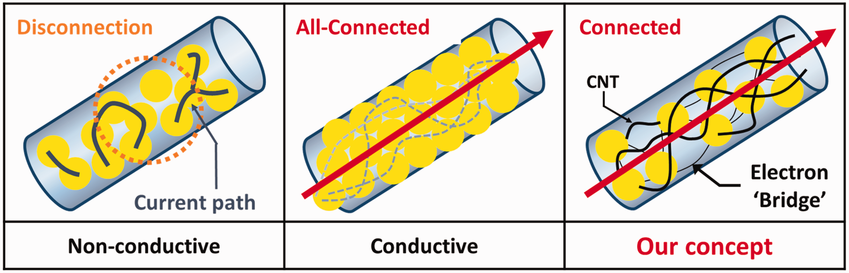
However, it is also hard to manufacture by a melt-spinning process because it is heavy and it is hard to control the dispersion of metal NW. Rigid and brittle metal characteristics are also problems interrupting the melt-spinning process. The hard-aggregated metal NWs block the nozzle spinneret. Overcoming all of these problems, in this study carbon nanotubes (CNTs) are suggested as an alternative to metal NW due to their light weight and highly conductive electrical and mechanical properties. Of course, much research has recently been reported regarding the fabrication of pure CNT fibers having high electrical conductivity by a solution or dry spinning process.24,25 However, they also have weak mechanical strength and elongation problems inappropriate to clothing or similar applications. This paper describes the preparation of an Ag/CNT/polymer composite fiber exhibiting highly conductive electrical properties and appropriate mechanical properties. A schematic of the concept is shown in Figure 2. Small amounts of CNTs easily create forest structures; therefore, they have the benefit of improving the probability of contact between the conductive materials. The bulk density of pristine CNT was considered to be 0.08 g/cm3. If only 5 wt% of CNTs is added, a volume effect of approximately 62.5% is given in composite fiber. In addition, flexibility, waviness, and the large aspect ratio of CNT forms percolated networks that induce a higher probability of contact; further, the fiber was extended at a low concentration.
SEM images of cross-section: (a, b) SEM images of cross-sections through Ag 80 wt%/polymer fiber fabricated by melt-spinning; (c, d) SEM images of cross-sections through Ag 95 wt%/polymer fiber fabricated by solution spinning. Schematic of the concept to fabricate “all” of the connected structure with low metal concentration and CNT.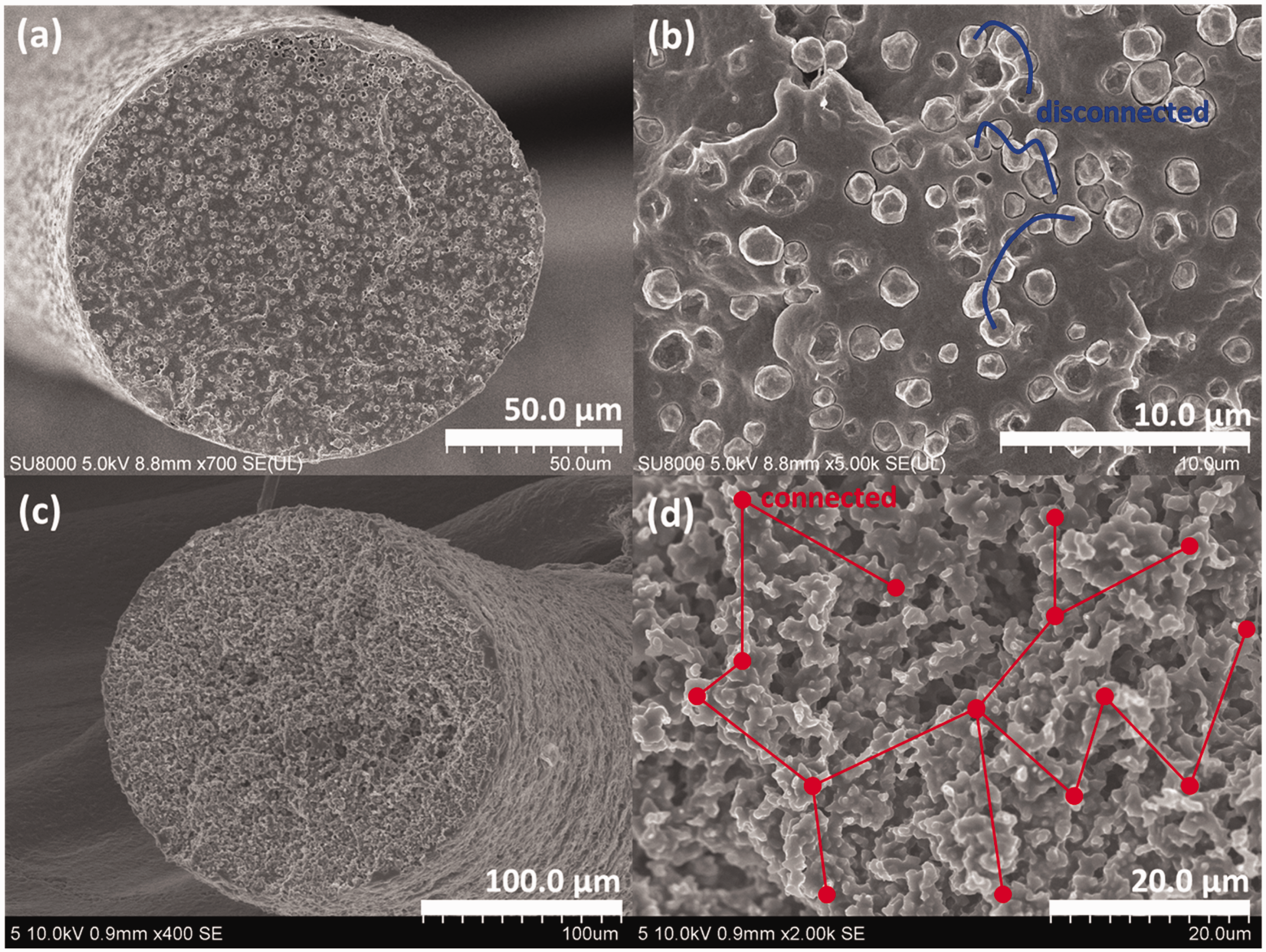
To reach the target, different sizes of Ag and various kinds of CNTs were selected as electrical conductor and electron connector, respectively. Various ratios of composite fibers for the melt-spinning process were prepared for a comparison of electrical conductivity and mechanical properties. Further, an electro-conductive fabric was manufactured using the optimum Ag/CNT/polypropylene (PP) composite fiber.
Experimental
Materials
Polypropylene (PP) (HP552R, Polymirae Co., Ltd, Korea) was purchased because it is an appropriate material for fabricating fiber by the melt-spinning process. Highly conductive Ag was purchased from NTbase Co., Ltd, Korea (NP-S80, spherical, 80 nm (Ag80)) and Green Resource Co., Ltd., Korea (plate type, 1–5 µm (AgM)) to compare the electrical effect according to the metal size. Multi-wall CNT (MWCNT) and single-wall CNT (SWCNT) were purchased from Kumho Petrochemical Co., Ltd., Korea (K-Nanos 100 T, diameter 10–15 nm, average bundle length 29 µm) and OCSiAl.ru LLC, USA (Tuball™, diameter 2 nm, length >5 µm).
Masterbatch preparation
Masterbatch (MB) preparation is the most important process for fabricating a uniform and highly electro-conductive fiber. This technique is highly effective for making a host thermoplastic with highly concentrated additives in a well-dispersed state. It is generally prepared by melt-mixing with the aid of an extruder. Most MBs contain a relatively high amount of additive because it is possible to simply dilute the contents in the thermoplastic for the end use. Thus, various trials were made to prepare an MB containing the maximum amounts of Ag and CNTs, to fabricate a highly electro-conductive fiber with well-dispersed high metal contents.
A twin-screw type compounding extruder (BA-11, Bautek, South Korea) with 11 mm screws was used to fabricate the Ag/PP and CNT/PP MB. Various attempts were made to select the optimum parameters such as extruder temperature, screw speed (r/min), feeding speed, etc. Screw speed is a major factor for determining output, dispersion, and thermal history. Low speed has a good effect on dispersion; however, it causes low production and degradation of polymer chains because more heat is applied to the polymer. The mechanical properties of the fiber are decided by the morphology of the polymer chains. To prevent the degradation of polymer chains, less heat should be applied by a low temperature and high screw speed. As a result, four types of MBs were prepared, taking manufacturing limits into account to gain all of the properties stated above. The ratios of MBs were as follows: Ag80:PP = 8:2 (Ag80 MB), AgM:PP = 7:3 (AgM MB), MWCNT:PP = 15:85 (MWCNT MB), and SWCNT:PP = 1:9 (SWCNT MB). These were determined after using thermogravimetric analysis (TGA) five times and determining the remaining weights of each CNT and Ag after the removal of PP by thermal treatment. These weights were similar to the weight of CNTs and Ag input. Thermal treatment was carried out through room temperature (RT) at 800℃ in an N2 atmosphere. The average remaining values were as follows: Ag80 MB 78.1%, AgM MB 68.2%, MWCNT MB 14.9%, and SWCNT MB 9.4%.
Fiber preparation
Ag/CNT/PP composite fiber was prepared using a single-screw type extruder (BAS-11, Bautek, South Korea) with an 11 mm screw. The single screw extruder is widely adapted to producing fiber because it is favorable for preparing fiber with regular properties. The important difference between the twin and single screw extruders is the method of transporting molten polymer from the feeder to the nozzle. The twin screw extruder moves the polymer by the force of screw rotation; while in the case of the single screw extruder the molten polymer in the barrel is transferred to the spinning nozzle by the force of continually fed polymer. Excessive CNT and Ag prevent elongation of the polymer; therefore, it is essential to adjust the content of the polymer composite to extend without breakage. A large amount of CNT in the PP gives a higher tensile strength because the CNTs act as an effective nucleation agent when crystallization occurs due to elongation. This result interrupts the elongation of the polymer because it makes the fiber stiff. While, in general, metal acts as an obstacle to generating the crystalline structure of the polymer; lots of metal in the polymer composite leads to breakage when the fibers extend. In this research, well-extended Ag/CNT/PP composite fibers were prepared with a high-speed winding system to control the ratio of Ag:CNT:PP by mixing Ag/PP MB, CNT/PP MB, and pristine PP.
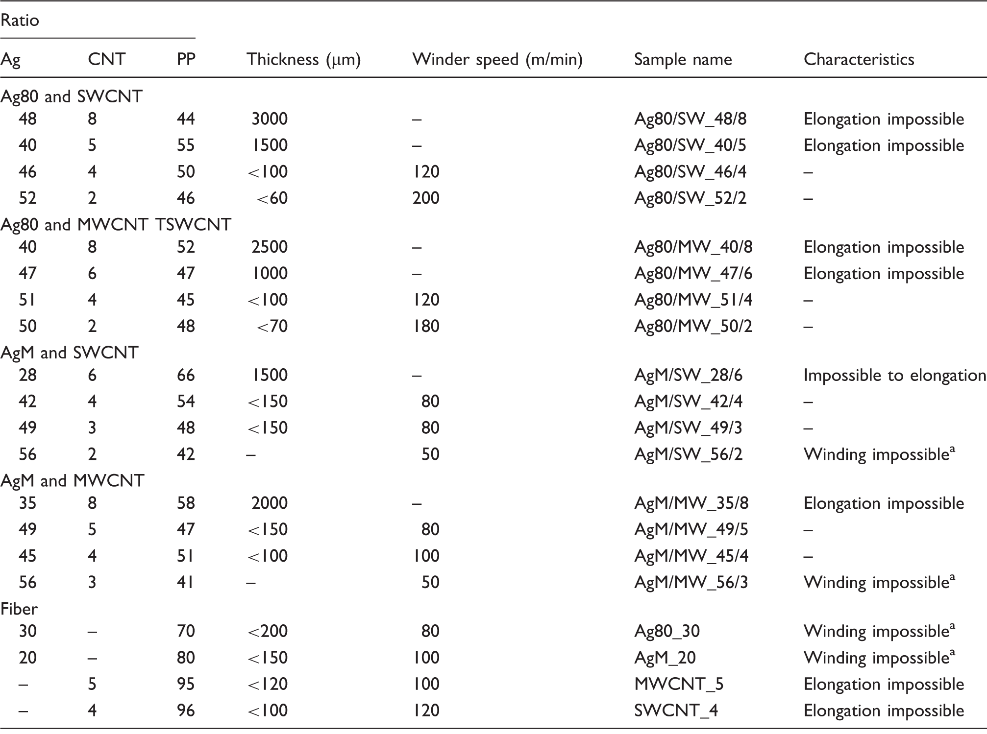
A single 1.0 µm hole and multiple 0.5 µm holes (10 holes) were used to fabricate composite fiber. The ratios for representative fibers are shown in Table 1. To prepare highly electro-conductive fiber, lots of Ag and CNTs should be embedded within the PP matrix. It was judged in this study that narrow (less than 1 µm) nozzles and multi-hole nozzles are unsuitable for allowing the fiber to contain a large amount of additives because the additives induce blockage of the nozzle holes and an increase of spin pack pressure. Therefore, a 1.0 µm size single-hole nozzle was selected for preparing highly conductive fiber. Thin fibers were collected by a high-speed winder running at 100–200 m/min. The schematics and images of the extruder are shown in Figure 3.
Schematic and photographs of (a) MB preparation device (twin-screw type extruder); (b) fiber preparation device (single-screw type extruder). Ag/CNT/PP ratios of representative composite samples reflecting fabrication possibility The as-spun fiber was impossible to wind for over 1 min because of its low viscosity.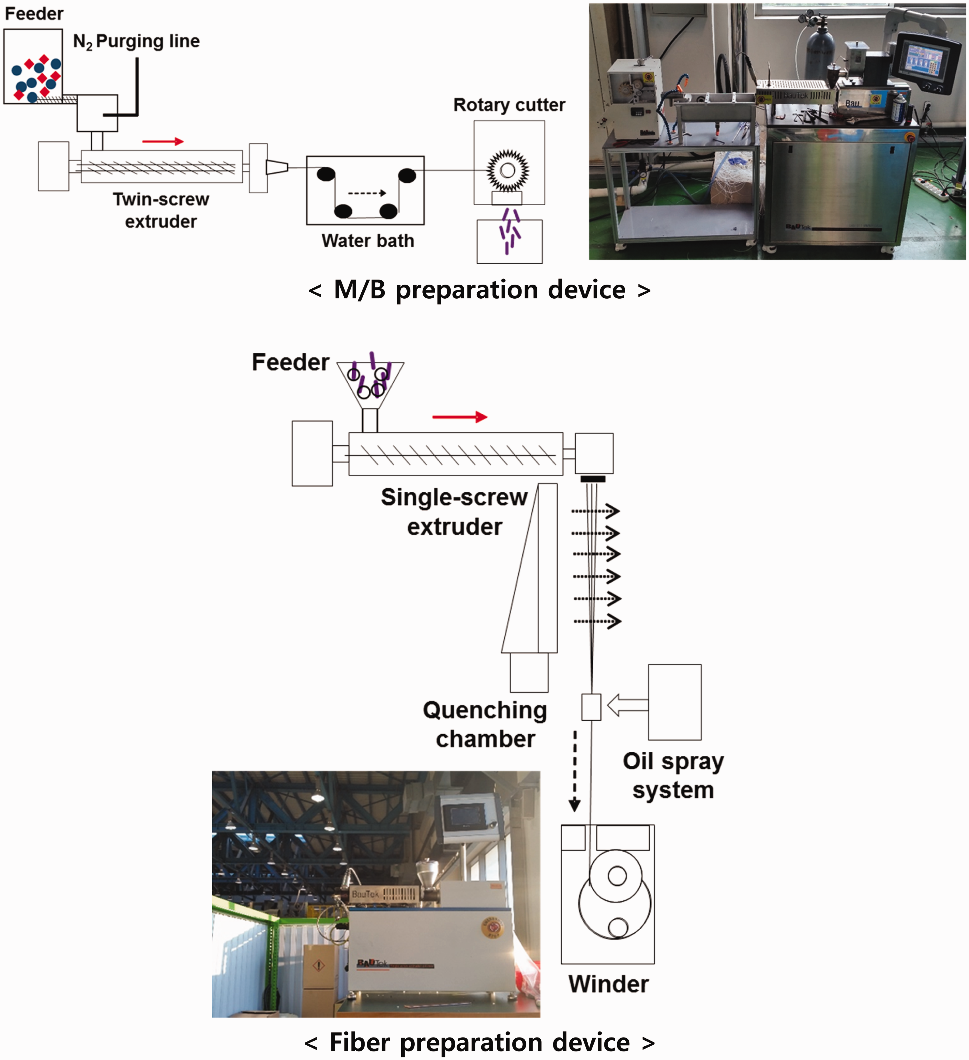
Characterization
Thermogravimetric analysis (TGA) (Q500, TA Instruments, USA) was used to confirm the weight ratios of Ag, CNT, and PP in the composite fiber. The melt-spinning temperature was predicted by differential scanning calorimetry (DSC) (Q100, TA Instruments, USA). The cross-section and fiber surface images were measured by field emission-scanning electron microscope (FE-SEM, SU8000, Hitachi, Japan), and Ag and CNT position in PP matrix was identified by SEM image using ultra high resolution FE-SEM (UHR FE-SEM, S-5500, Hitachi, Japan).
The electrical conductivity of composite fibers and strands were converted on the basis of thickness and electrical resistance. Four-point probe measurement (CMT-100 S, AIT Co., Ltd., Korea) and two-point probe measurement (HiTESTER 3280-20, HIOKI E.E. Corp., Japan) were used for confirming sheet and linear resistance, respectively. The four-point probe machine is generally applied to sheet material. Fiber is too sharp to measure electrical resistance with a four-point probe machine; therefore, it was used to analyze the electrical resistance of strand types to compare with the electrical results obtained by two-point probe measurement. The conversion equation to find electrical conductivity is

A two-point probe is suitable for confirming the electrical properties of fiber-shaped samples. Silver paste and an insulating glass plate were applied to measure the electrical resistance of our composite fibers. The electrical conductivity measured by the two-point probe machine (S2-point) was calculated as
Results and discussions
Master batch preparations
As described in the Experimental section, four types of optimum MB were prepared on the basis of the maximum quantities those were possible to process. Figure 4 exhibits the cross-sectional images of CNT and Ag based MBs. The extruding period was considered, providing over 5 min of residence time in the barrel to enhance dispersion properties. Screw and rotary cutter speed were set to enable a continuous production process. MWCNT and SWCNT at concentrations of 20 wt% and 15 wt% in PP MB were prepared, and it was judged that the contents of each CNT were the maximum amounts possible to process by melt-spinning. The major problem fabricating CNT/polymer composite is that the CNT contents in a composite material cannot be translated to the input of CNT without a precise geometrical theory, input environment, bulk density, and mixing conditions. Hot-pressed pellet type CNT was introduced to increase CNT content in the MB. It was investigated that the density of SWCNT was lower than that of MWCNT with the same outer diameter.
26
Further, the bulk density difference between SWCNT and MWCNT was larger than that of the intrinsic density due to their electrical repulsive force and configuration. Accordingly, it was judged that the maximum MWCNT content was higher than that of SWCNT for these reasons. It was determined five times by TGA test that the remaining weights of each CNT after removal of the polymer matrix by thermal treatment were nearly similar to the weight of input CNTs. As the large amounts of CNTs were above 10 wt%, they started to agglomerate and form a large bundle in the polymer matrix. This disturbs the extension of the polymer composite; therefore, it was hard to manufacture the composite fiber with excessive CNTs by continuous process.
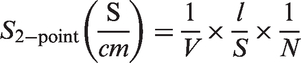
SEM images of cross-sections through MBs: (a) MWCNT MB; (b) SWCNT MB; (c) Ag80 MB; (d) AgM MB. The MB pellets and their electrical conductivities are shown in the inset images.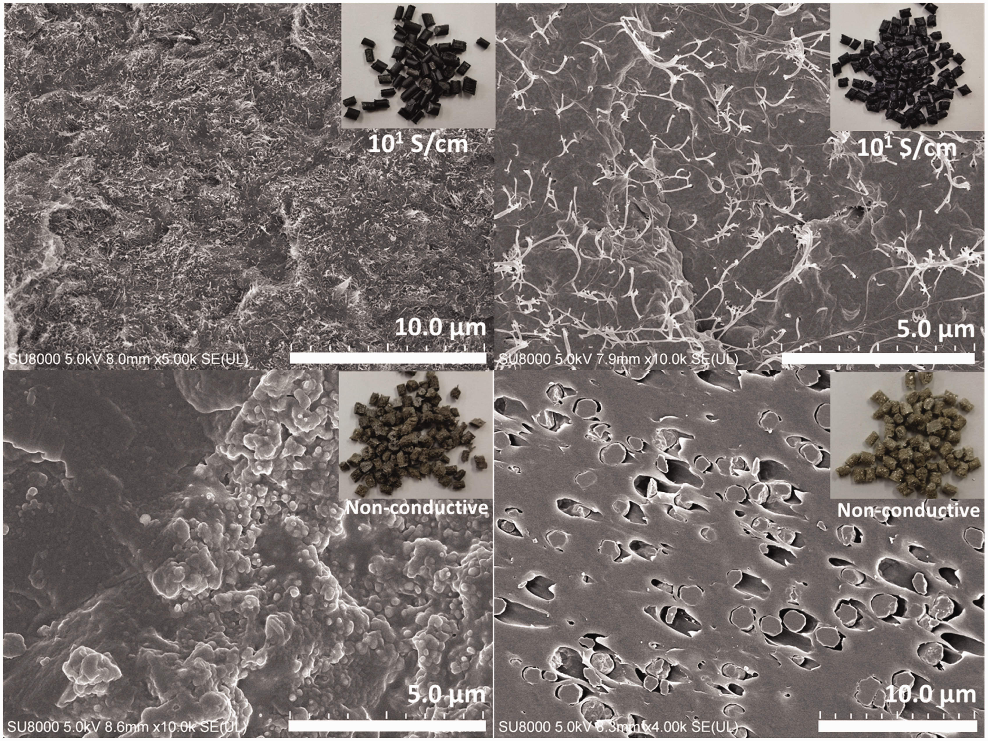
In contrast, excessive Ag provides the composite with a very low viscosity due to interruption of crystallization of the polymer. Therefore, it was also difficult to produce the Ag/PP strand for this contrary reason. It was confirmed that 80 wt% of Ag80 and 70 wt% of AgM were the maximum amounts for fabricating Ag MB by continuous process. The degree of agglomeration was determined from the MB cross-sectional SEM images. AgM was generated by a chemical process and was coated by chemical dispersant, while Ag80 was prepared in a pure metal state by a plasma technique. Figure 4(c) and (d) show the dispersion results that come from manufacture. Regarding the effect of the w/ and w/o dispersant, dispersion exhibits an obvious difference between AgM and Ag80. In general, it was a major problem to fabricate a composite structure that influenced the regular properties. However, it was judged that dispersion was not a significant problem in our study because we put an overriding focus on the contact between the conductive materials. In addition, MB results were just intermediate states toward the final form; therefore, we decided against paying attention to the dispersion problems. Photographs and the electrical conductivities of four different MBs are given as insets in Figure 4. Electrical conductivity of MBs was measured by the two-probe method.
In spite of the difference between amounts of CNT, MWCNT and SWCNT MB show similar electrical conductivity: approximately 100 to 101 S/cm due to the electro-conductive mechanism. The conductive path of SWCNT creates only a conjugated structure that shows much lower electrical resistance than that of MWCNT, which includes other electrical paths among the different walls.27,28 The conductivity (very low) of both Ag-based MBs was not measured because of the insufficient amounts of contact ruled by the packing fraction, as stated above. The fabrication temperature profiles of the twin screw type extruder were as follows: SWCNT MB 220℃ (head)–220℃–220℃–220℃–180℃–130℃ (hopper), MWCNT MB 210℃ (head)–210℃–210℃–210℃–180℃–130℃ (hopper), and Ag80 MB and AgM 180℃ (head)–190℃–190℃–190℃–160℃–130℃ (hopper).
Composite fiber preparations
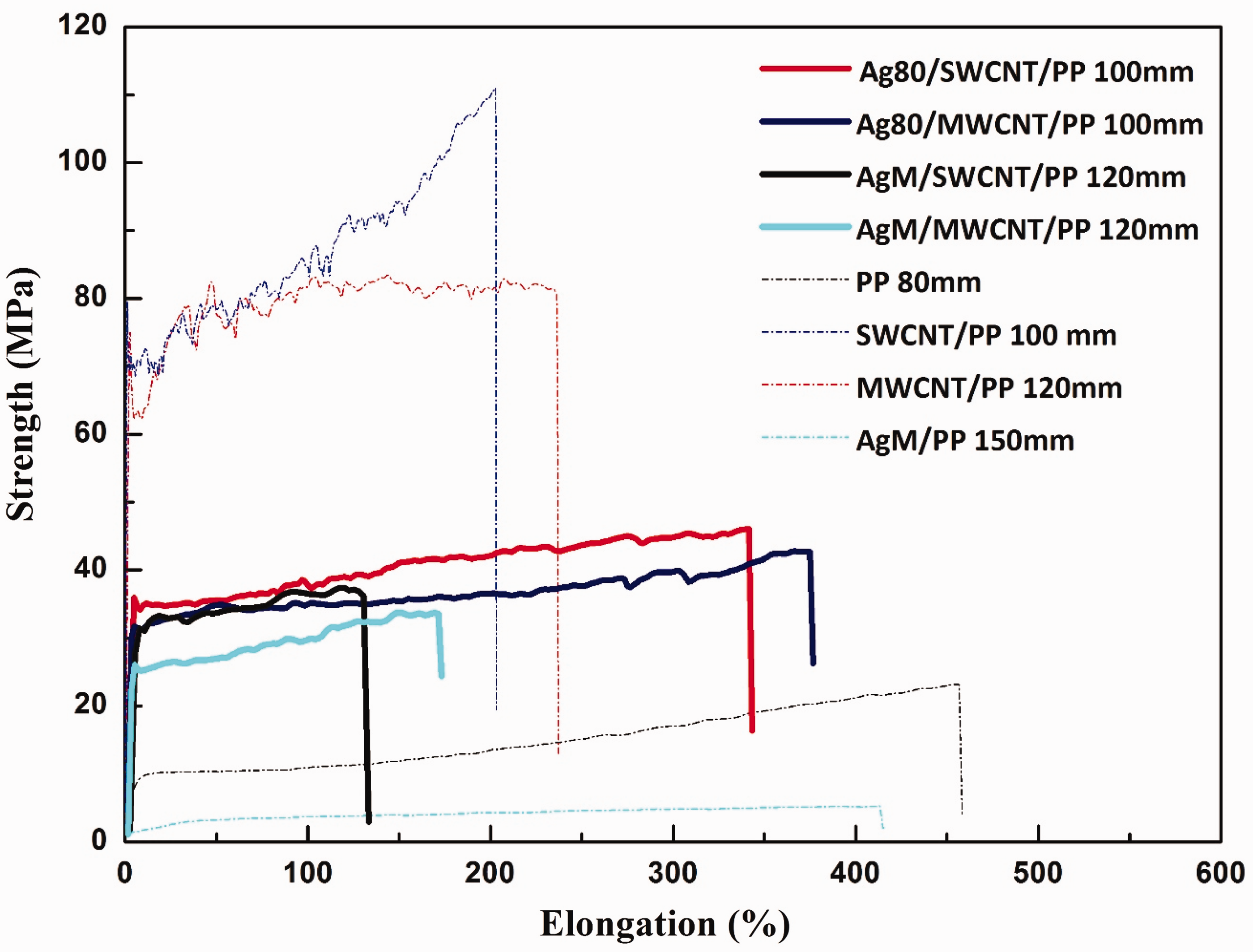
Table 1 illustrates the thicknesses of representative composite samples according to the ratios of Ag:CNT:PP for identifying possibilities of fiber preparation. To fabricate thin and highly electro-conductive composite fiber, various MBs and pristine PP were blended and stretched by a winder. Photographs of the fibers are shown in Figure 5. The maximum contents of additive/PP composite filaments were as follows: Ag80:PP = 30:70, AgM:PP = 20:80, MWCNT:PP = 5:95, and SWCNT:PP = 4:96. The more additives that were embedded, the more difficult were the CNT/PP filaments to fabricate due to brittleness. It was also hard to stretch Ag/PP filaments because they have low viscoelasticity. It was expected that these conflicting behaviors have a complementary effect after mixing Ag, CNT, and PP together. The Ag content of stretchable composite fiber was largely increased by the properties of the CNT (Table 1). Overall, Ag80 embedded CNT/PP composite fiber was favorable for the manufacture of a thin filament when compared to embedded AgM. It is thought that the micro-sized Ag act as a destroyer of polymer chains; therefore, they make weaken the elongation properties. After the trials, Ag80:SWCNT:PP = 46:4:50 (Ag80/SW_46/4), Ag80:MWCNT:PP = 51:4:45 (Ag80/MW_51/4), AgM:SWCNT:PP = 49:3:48 (AgM/SW_49/3), and AgM:MWCNT:PP = 49:5:47 (AgM/MW_49/5) were selected as the optimum fibers for each material. Figure 6 gives the overall results. First, the strength of the composite fibers fabricated by the melt-spinning process show outstanding mechanical strength compared to the fiber from the solution-spinning process. This is the reason why we adopted the melt-spinning process despite the difficulty of fabricating a composite fiber containing excessive additives. The strength of Ag/CNT/PP composite fibers is higher than that of Ag/PP fiber due to the CNT effect. Polymer chain destroys the effect on AgM as confirmed by the elongation result comparing CNT/PP and Ag/CNT/PP. Mechanical strength drop following Ag content increase is called “brittle fracture,” which induces polymer deformation at the interfaces within Ag embedded polymer during stretching.29,30 The deformation serves as a defect and it was judged that it leads to a drop in strength. Often with melt-spinning situations, AgM/CNT/PP composite fiber shows elongation properties lower than those of other composite fibers. Ag80/CNT/PPs exhibit what we want, having moderate strength and elongation to adapt to fabric applications. Although these composite fibers have lower strength than the composite fibers inserting CNT alone, they enable the manufacture of thin filaments under 100 µm thickness and more flexibility favorable for use in cloth.
Photographs of continuous Ag/CNT/PP fibers obtained from optimum melt-spinning conditions. (a) 150 µm, 180 µm, 80 µm, and 90 µm fibers; (b) Ag80/SWCNT/PP; (c) Ag80/MWCNT/PP; (d) AG80/SWCNT/PP. Mechanical properties of composite fibers. AgM/PVDF 150 µm was fabricated by the solution-spinning method (AgM/PVDF = 95/5).
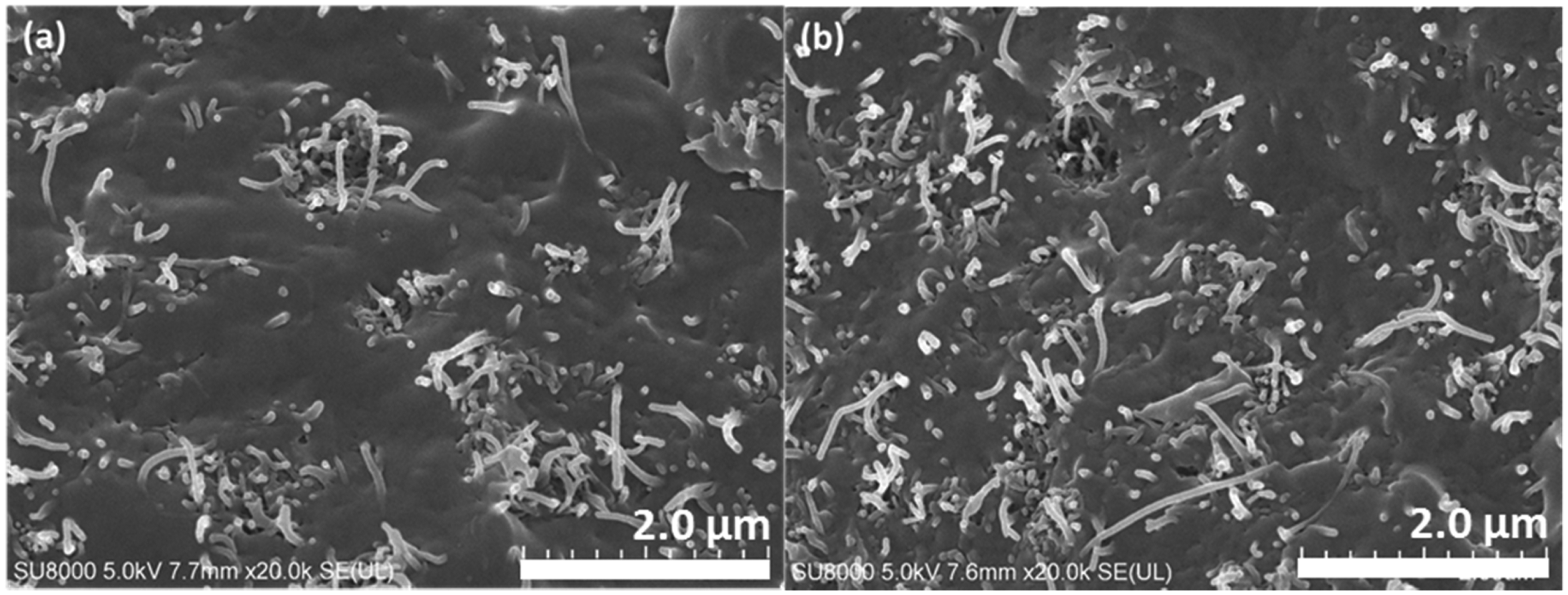
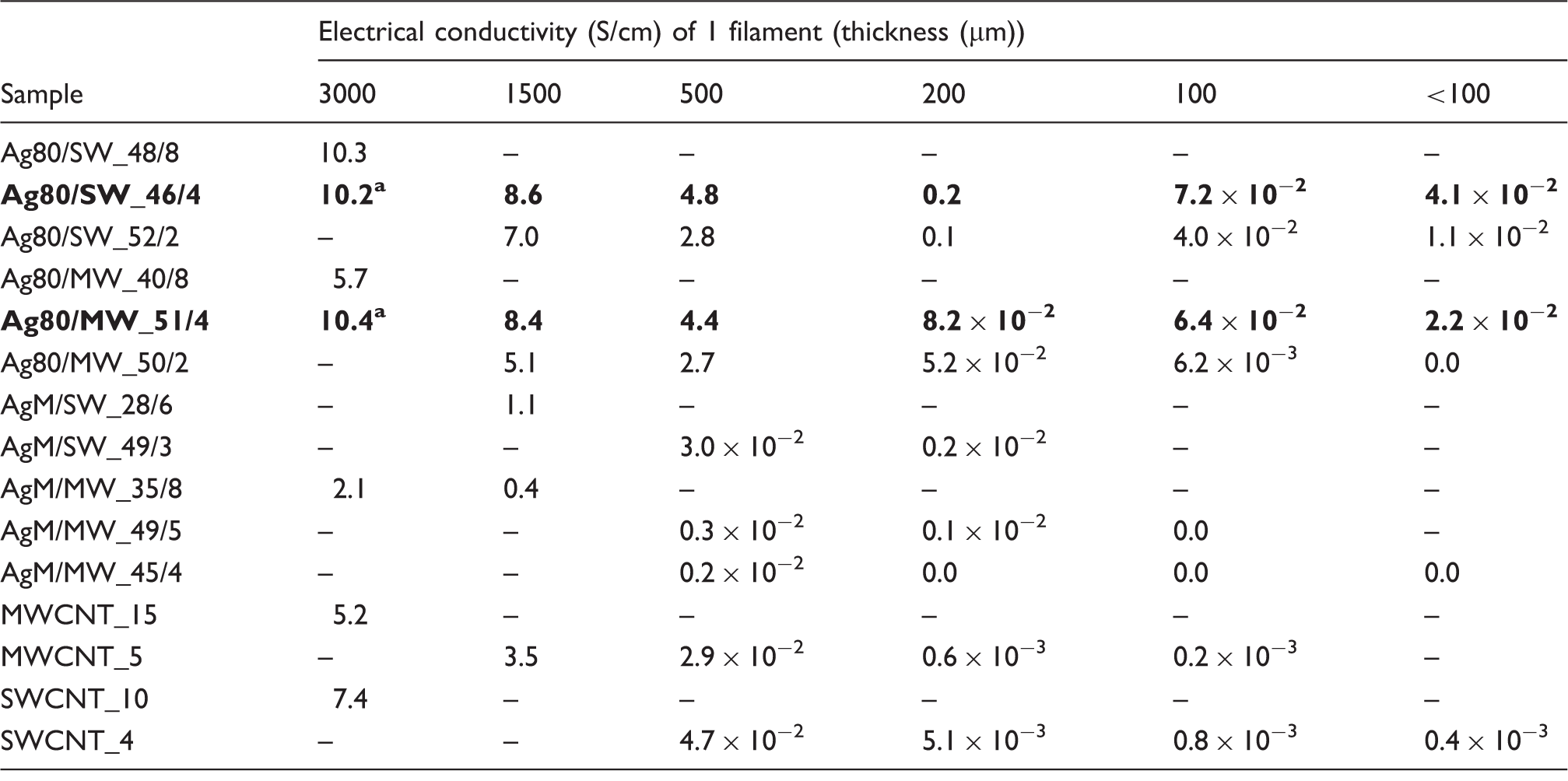
The electrical conductivity results confirmed the Ag-CNT network effect shown in Table 2. As verified in the MB preparations, the Ag/PP (80/20) pellet has no electrical properties and Ag80/PP (30/70) and AgM/PP (20/80) composite fibers also do not show an electrical signal; however, the electrical conductivity of CNT added to the Ag/PP pellet shows approximately 101 S/cm. This is evidence confirming the benefits of CNT networks. This effect is more powerful in thinner filaments. The electrical conductivities of Ag80/SW_46/4 and Ag80/MW_51/4 were 4.1–7.2 × 10⁻² S/cm and 2.2–6.4 × 10⁻² S/cm at less than 100 µm thickness, respectively. These values are approximately 102 times higher than the electrical conductivities of CNT/PP thin filaments alone, in spite of having similar CNT contents. In addition, interestingly, it was confirmed that CNT alignment was changed in the Ag/CNT/PP composite fibers, in contrast with the CNT morphology of CNT/PP fibers. Figures 7 and 8 illustrate the CNT configurations according to the degree of stretching. SEM images of the elongation of Ag80/SWCNT/PP fibers are shown in Figure 7. It was confirmed that random-coiled SWCNT was arranged in an extended direction through the high-speed winding process. When compared to the images of composite fiber without Ag under the same conditions (see Figure 8), it was verified that there is not much difference between the SEM images of the drawn direction at low and high velocity, 50 and 120 m/min, respectively. It is widely known that well-aligned CNT has a positive effect on the electrical and mechanical properties of CNT/polymer composites because of its percolation threshold.
31
This is also the reason why the electrical conductivity of Ag80/SWCNT/PP composite fiber was higher than that of CNT-embedded PP fiber alone.
SEM images of Ag80/SWCNT/PP composite fibers of different thicknesses: (a) 550 µm (undrawn); (b) 150 µm; (c) 90 µm; (d) schematic showing the direction in which the images below were taken; (e) extended by winder speed of 50 m/min, ×10,000; (f) extended by winder speed of 120 m/min, ×10,000; (g) extended by winder speed of 120 m/min, ×1,000. SEM images of elongation direction of SWCNT/PP composite fibers according to the drawn speed: (a) 50 m/min; (b) 120 m/min. Electrical conductivity of various Ag/CNT/PP composite filaments according to the filler type and fiber diameter Pellet.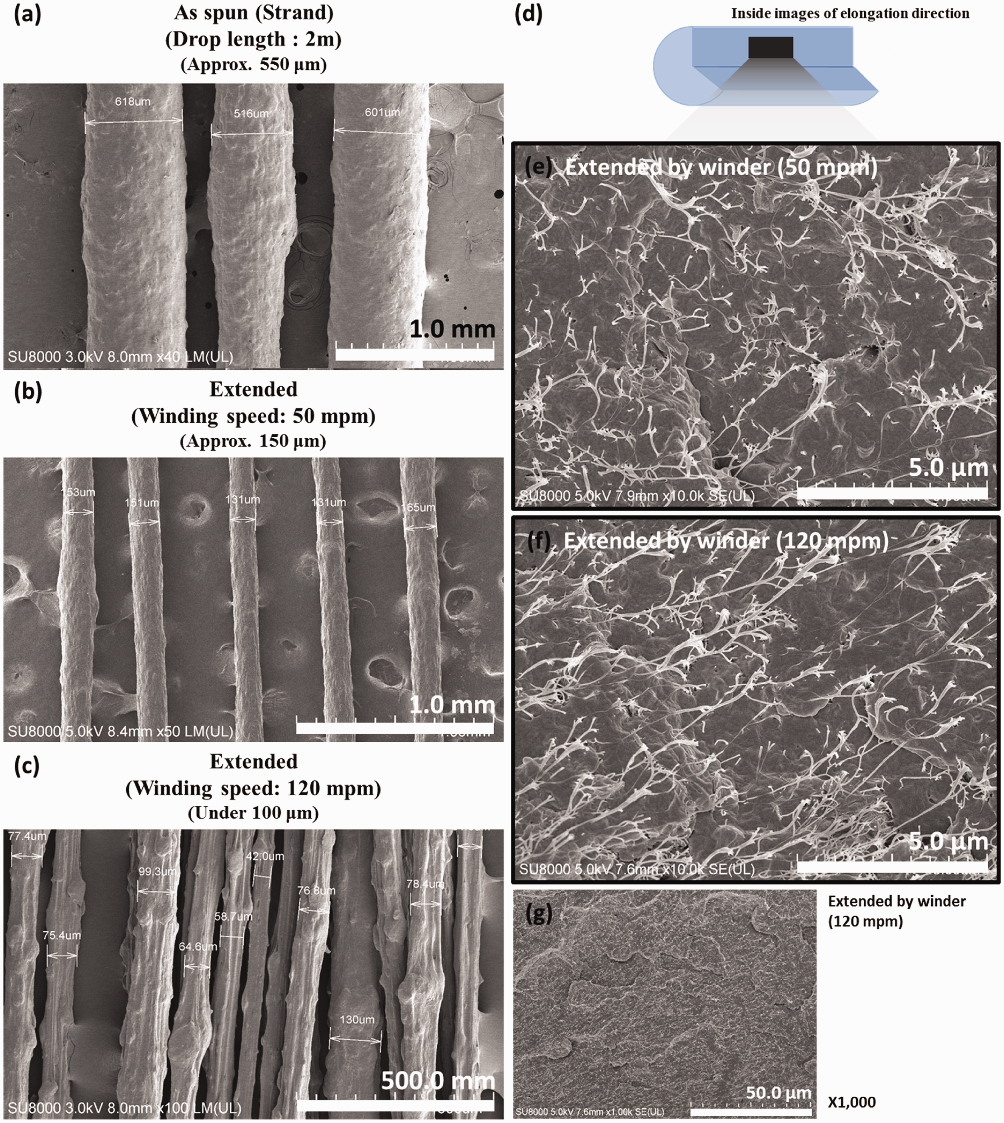
Both CNTs and metals are conductors, theoretically showing over 105 S/cm. However, there are two drawbacks that have been verified in applying this concept successfully. The minor one is the agglomeration of Ag and CNT in the polymer matrix, leading to a poor synergic effect with the additives disconnected. The major one is different electrical conducting behaviors. The metal Ag forms in a lattice structure of atoms, which has an outer shell of electrons that freely dissociate from their core atoms and float through the lattice. These dissociated free electrons allow Ag to conduct electric current. The electro-conductive mechanism is similar to the transfer of momentum of balls in the Newton's cradle.32,33
CNT is chemically composed of just C and H, and all of the Cs are bonded, forming a continuous hexagonal structure. The conducting paths are created in this structure between unpaired electrons forming new π-bondings. This behavior is different from that of metal because of the travel of dissociated electrons. Therefore, it was decided that a large resistance occurred when Ag and CNTs were in contact; although both are conductors and they can each take part in electrical flow. This assumption was supported by the following tests. To measure the electrical conductivity of conductive fibers, conductive paste was generally used, and it should act as a superconductor. However, the results show that electrical resistance occurs if different kinds of conductors are encountered. Actually, the electrical conductivity of carbon fiber (100,000 S/cm, Mitsubishi Plastics, Inc, Japan) was measured to be somewhat higher when carbon paste was used when compared to the result of applying Ag paste. On the contrary, the result of using Ag paste was higher than the result of using carbon paste when the electrical conductivity of Ag wire (approximately 200,000 S/cm) was measured. Although it was identified that the major reason why the electrical conductivity of Ag/CNT/PP composite fiber shows a lower value than Ag/PP was the different conductive behaviors, the CNT forest acts as a conductive bridge and highly the electro-conductive Ag combination was considered to be optimized in terms of cost, productivity, and the ability to be processed. Therefore, it is thought that other approaches are necessary to enhance electrical conductivity without changes of conductive material.34,35
Ag80/SWCNT/PP fabric preparations
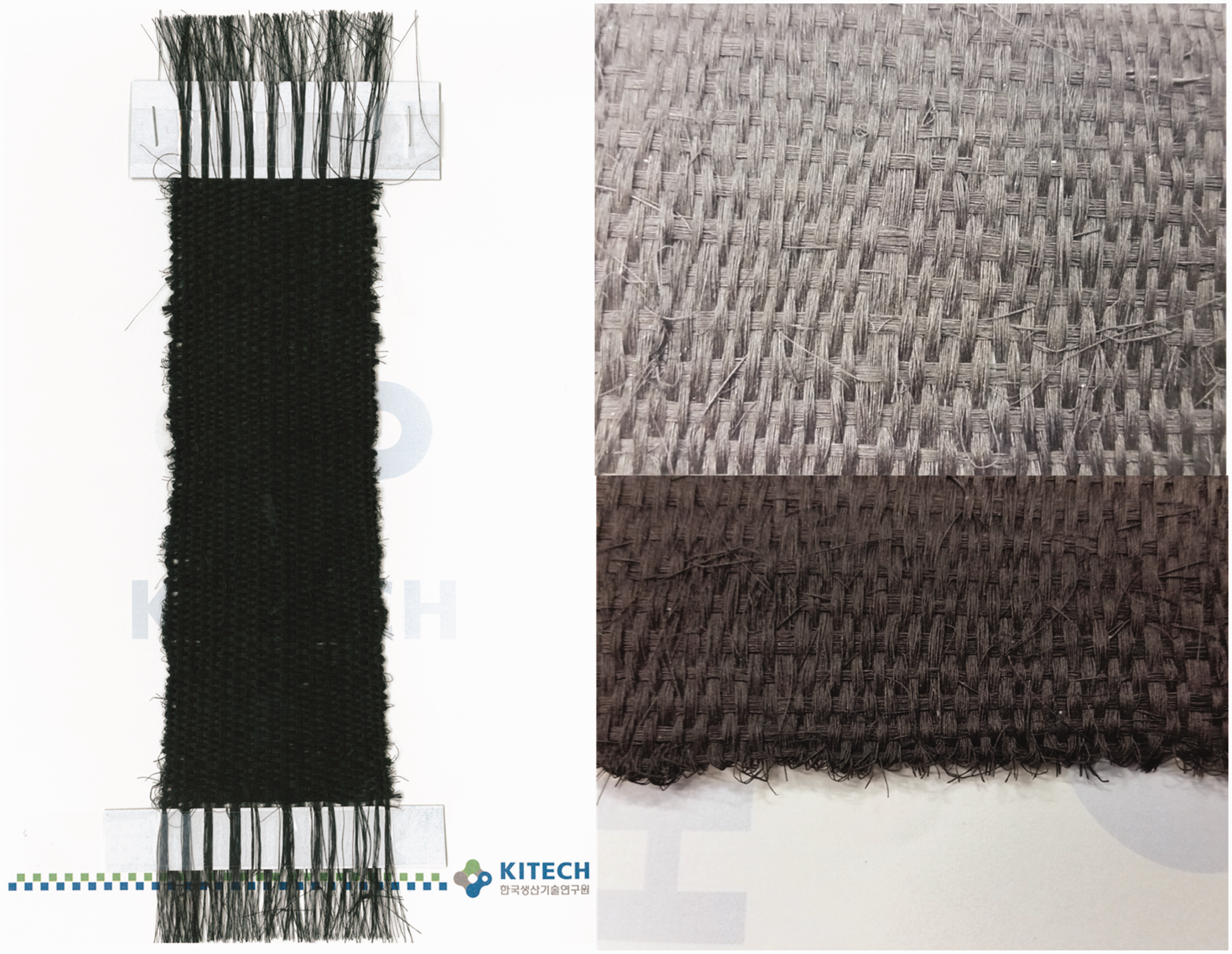
In the practical world, fiber is not used as a single filament itself; rather, the textile form is fabricated using multiple filaments. In accordance with basic electrical theory, a larger cross-sectional area of conductive fibers leads to lower electrical resistance. According to this theory, multi-filaments will increase the cross-sectional area. In Figure 9(a), it is shown that the resistance drastically dropped upon increasing the number of filaments of Ag80/SW_46/4. Converting this to electrical conductivity, 7.0 S/cm is obtained from 50 multi-filaments. This conductivity value is regarded as being suitable for applications such as chemical sensors, and antistatic and electromagnetic interference (EMI) shielding. In addition, the conductivity of multi-filaments exhibits a similarity with the strand equal to the sum of the fiber cross-sectional area shown in Figure 9(b). Multi-filaments are favorable in terms of fabric and cloth applications because of their bendability and transformable properties with the same electrical conductivity. Figure 10 shows photographic images of a conductive fabric using Ag80/SW_46/4. The electrical conductivity obtained from this fabric was measured at a range of 10−1–101 S/cm, though this is not a great electrical value, however, it has quite a significance.
Electrical properties of according to: (a) the numbers of filaments; (b) sum of fiber cross-sectional area comparing multiple fibers and strand. The red line in (a) is the electrical conductivity of single filaments. Photographic images of Ag80/SW_46/4 fabrics manufactured as a plain weave: original image (left) and ×100 magnified images (right).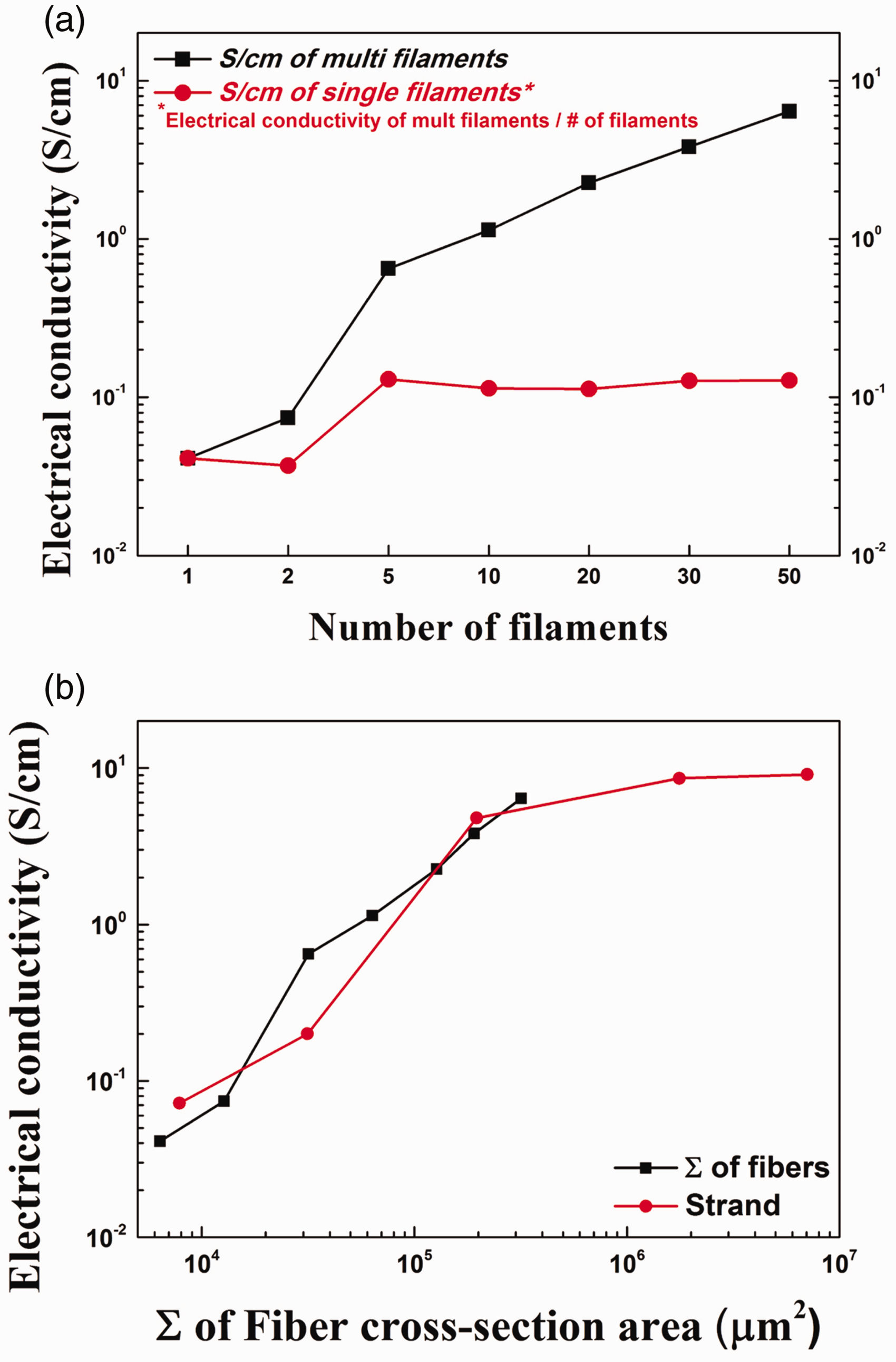
Conclusions
We have demonstrated the manufacture, using the rarely attempted melt-spinning process, of highly conductive Ag and CNT embedded conductive fibers, that are of high strength and are suitable for mass production. The melt-spinning process has a lower additive threshold than other spinning methods; therefore, it is impossible to fabricate a fiber in which all of the Ag is connected. CNT was introduced as an electron bridge to form a forest structure for connecting Ag. Taking the ability to be processed into consideration, 80 nm Ag (Ag80) and SWCNT are optimum materials adopted in our research. Ag80 (80 wt%) embedded PP composite has no electrical properties. However, Ag80 (46 wt%) and SWCNT (4 wt%) embedded PP composite shows an electrical conductivity of 10.2 S/cm with the aid of CNT percolations. These are the threshold ratios for fabricating continuous thin filaments under 100 µm and 4.1 × 10⁻² S/cm to 7.2 × 10⁻² S/cm electrical conductivity obtained for a monofilament. It gives mechanical strength of 40 MPa, which is 10 times higher than the composite fiber fabricated by the solution process. The final object, a conductive textile, was fabricated successfully and the electrical conductivity was within the range of 10−1 S/cm to 101 S/cm. Although this is not a useful electrical value, we believe that our composite fiber has a potential that can be applicable to various kinds of wearable electrical devices.
Footnotes
Declaration of conflicting interests
The authors declared no potential conflicts of interest with respect to the research, authorship and/or publication of this article.
Funding
The authors disclosed receipt of the following financial support for the research, authorship, and/or publication of this article: This work was supported by the Industrial Material Technology Development Program (Project Number 10048884) funded by the Ministry of Trade, Industry, and Energy (MI, Korea) and GRI's Institutional Program of Ministry of Strategy and Finance (Korea Institute of Industrial Technology (grant number EO150010).