
Abstract
In this work, based on the geometrical model given in Part I, a mechanical model is created for dry relaxed slack plain knitted technical fabrics including the three-dimensional friction effects. The equilibrium of forces and moments applied on a loop are written by using the elasticity theory of thin rods. Through this model, it is shown that a dry relaxed plain knitted fabric can be in a stable state induced by friction. The application of the model was carried out on E-glass technical fabric, which was also used in Part I as its dimensional properties were obtained through the created geometrical model. In the current part, Part II, the mechanical properties of this fabric are obtained and discussed as an exemplary application.
Introduction
As explained in Part I, 1 the shape of a dry relaxed plain knitted loop is different from the tight ones. Here, a force system in the state of equilibrium, including friction restrains, will be given in order to obtain the shape given in Part II, 1 particularly for the benefit of technical fabrics.
The literature on the subject was given in Part I; therefore, it is not repeated here.
Creation of the model
Assumptions
The yarn is taken as an elastic thin rod with a circular diameter, and its natural stress-free configuration is assumed to be straight in its dry relaxed condition. The shape of the loop is assumed to be obtained as in Part I
1
(see Figure 1). In dry relaxed slack fabrics, no jamming occurs and no external forces should be applied. The geometrical model of the slack plain knitted fabric as was created in Part I of this series of papers.
1
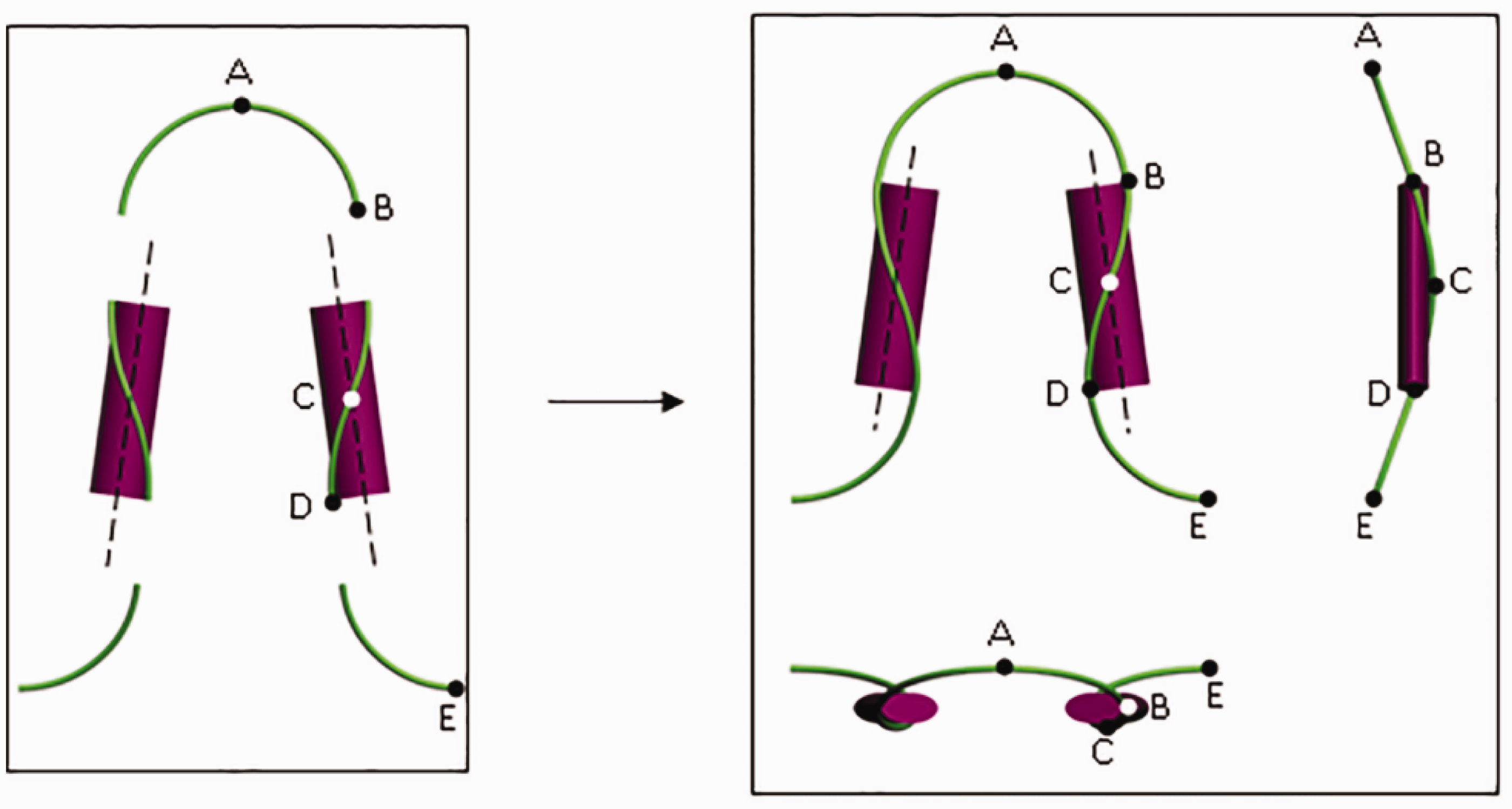
Only horizontal reaction forces apply to the loop arms at the interlocking points. Therefore, the loop head curve was assumed to be circular in shape and to be bent to this shape only by the moments, as considered by some of the researchers such as Munden
2
and Postle and Munden3,4 in their two-dimensional (2D) models. In this paper, it will be discussed that loop heads can have an elliptical shape without external forces and moments. However, in spite of this argument, the loop head curve will be assumed to be circular for simplicity reasons, as assumed by the previous works and as seen in Figures 2 and 3.
Yarn bending moments applied to the loop head. The components of the yarn bending moment applied at the right-hand side of the loop head.
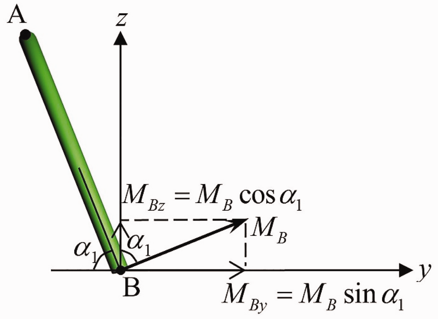
Since the loop head is inclined towards the third dimension (thickness direction) by the angle
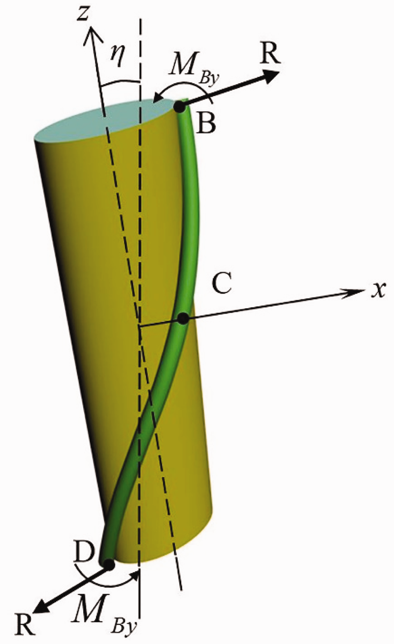
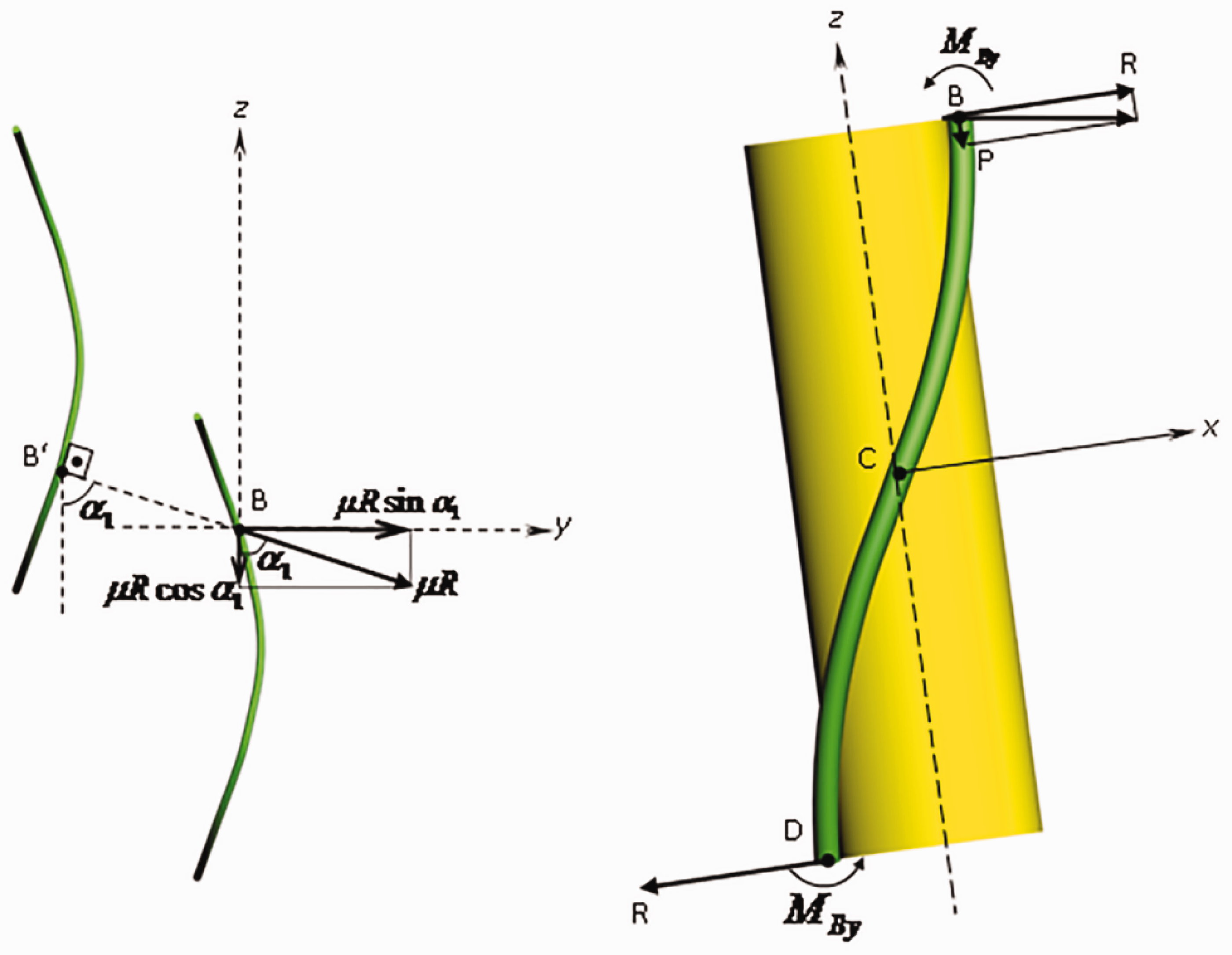
In the fabric plane, interlocking reaction forces are assumed to be concentrated forces R that apply at B and D (see Figure 4). These forces are assumed to be perpendicular to and passing through the yarn axis. Also there are Three-dimensional (3D) friction restrains are assumed to affect the loop shape as given in Figure 5. Friction forces applied on a loop according to the present model.
This friction force
As explained in previous works,2–6 in relaxed fabrics, there no external forces should be applied in the vertical direction or in the horizontal direction. Therefore, it is assumed that the vertical component of the reaction force R is equal to the friction component
Postle and Munden3,4 and Shanahan and Postle
6
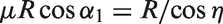
pointed out the friction occurring between the loops. Accordingly, they considered an interlocking angle β and explained the friction coefficient as μ = tan β. The interlocking angle β = 5° was observed as found by them. The same value for the interlocking angle as about η = 5° is found here in this study. When the friction equation is put as
Using the above-given arguments, the friction force is taken as in Figure 5, which is not parallel to the yarn axis at B in this model. It should not be forgotten that the relaxation takes place without any external forces and through solely the bending energy of the yarn. Therefore, it is thought that the movements between the loops during relaxation take place in the opposite direction of the friction force given in Figure 5.
Classical torsion is composed of two terms. Love
7
gives the formula as
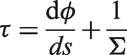
The first term, which is the torsion that is directly given to the rod before the three-dimensional bending, is defined as the differentiation of the Euler angle φ with respect to the rod length s. Euler angles and direction cosines can be found in some previous papers such as the paper of Shanahan and Postle. 6 They are also outlined in Appendix 1.
The second term is the tortuosity of the curve.
In one solution of Love 7 for “thin rod bent and twisted by terminal forces and couples”,
τ = constant
is used. Previous researchers5,6 that worked on the mechanical modeling of the plain loop used the same equation. Since the torsion τ should be equal to zero at point A on the plain loop head (Figure 1), most researchers have assumed the torsion τ to be constant and equal to zero for the whole length of the loop.
In this model, however, in Assumption 2, it was explained that the shape of the loop would be taken as given in Part I. 1
When the tortuosity of the arm curve of the model given in Part I is drawn (as in Figure 6), it can be seen that it is not constant, that is to say, zero at points A, B, D and maximum at point C.
Radius of curvature and torsion applied on Kurbak’s model as given by Kurbak and Ekmen.
8

In this model, it is assumed that the first term of the torsion equation vanishes. This assumption was inspired by the last paragraph of the case “270 Rod bend to helical form” (the equations of spiral springs), which was analyzed by Love 7 on page 415 of his book. It is assumed that the loop arm can also be regarded as a spiral spring; therefore, the torsion is equal to the tortuosity of the three dimensional loop arm curves. The case that was analyzed by Love has a constant torsion, however, there, the system was wrenched by other means. In the present case of the knitted loop, the yarn itself creates wrenches at the ends; thus, it is normal for the loop to have changing tortuosity.
In conclusion, in the present model it is assumed that the torsion is equal to the tortuosity of the curve. The tortuosity, in turn, is not constant as given in Figure 6. Since the tortuosity or torsion is equal to zero at the loop head point A, the argument given by previous researchers3–6 on this issue is also satisfied. Also, there is assumed to be a trapped torsion in the yarn arm in the present model. Thus, the torsion is assumed to be as

Equilibrium of forces and moments applied on a loop arm
Considering the assumptions made and the geometrical model given in Part I,
1
forces and moments applied on a loop arm are shown in Figure 7. The Euler angles (see Appendix 1) will be used as the coordinate system and the theory of elastic thin rods will be applied. Therefore, the loop arm shape shown in Figure 7 is drawn in accordance with these. Since the loop is symmetrical, a quarter part of it is enough to solve the whole loop. The ABC part of the loop is chosen for the calculation of forces and moments.
Forces and moments applied at the right arm of a loop according to the present work.
A suitable system of equations of an elastic thin rod was given by Hepworth and Leaf,
5
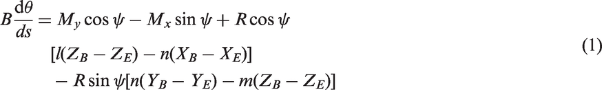
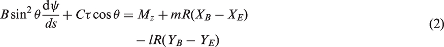
as explained below. According to this analysis, when the coordinates of point B in Figure 7 are known, the equilibrium of forces and moments at a point E on the axis of the elastic thin rod are given by the equations
It should be noted that in Hepworth and Leaf’s work,
5
In the present case

Since the shape of the loop is assumed to be as given in Part 11 (Assumption 2), the equalities
The moments My and Mx can be shown to be equal to the moments at the loop head in Figures 2 and 3. Changing the coordinate system, the equations are obtained as below.

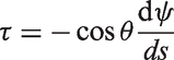
The torsion τ is given (using Assumption 5 and Related equation of Appendix 1) as
The equations below are obtained, by putting all these explained parameters in equations (1) and (2), for the equilibrium of forces and moments that are applied on the point E on the yarn axis.
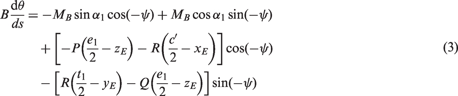
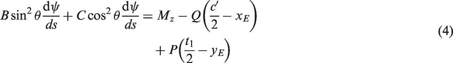
When point E is taken as the point C in the middle of yarn arm, the following equalities have to be written:
When the above equalities are put in equations (3) and (4) and are divided by the bending rigidity B, the following equations are obtained:


Below equalities can be put in equations (5) and (6)


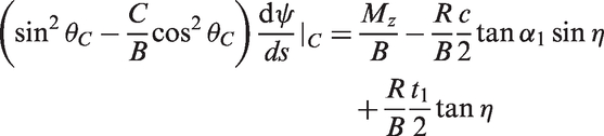
The point C is an inflection point in the xz plane, therefore


It should be noted that, since an approximate parabolic curve is used as the loop arm curve in this work,
An approximate solution of equation (8) can be obtained by using the geometrical model given in Part I. 1 The transformation of the coordinate system from the Euler angles to the present system is necessary; thus, it is given in Appendix 2.
In Appendix 2, it can be seen that the following equalities between the coordinate systems can be obtained
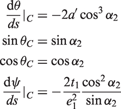
When these equalities are put in equation (8), an expression is obtained for
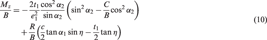
In equations (9) and (10) the parameter η is related to friction as

If one assumes that there is negligible friction effect, the equations (9) and (10) should be as
aThis Mz moment is the moment required to keep the loop arm in its shape and is smaller than


Therefore, the friction effect on reaction force R and Mz moment can fully be established by the present model. Furthermore, since the inclination angles η of the yarn arms are related to friction, the shapes of loops are related to friction; and thus, the present model can fully establish the shape of a loop. It can be said that a dry relaxed slack plain knitted fabric is in a friction induced stable state.
Some other effects of friction
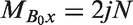
It is known that apart from the reaction forces R and their friction effects, the Mz moment is created by a couple of forces at the loop interlacing region, as given in Figure 8.
Wrenches 2N.p of the Mz moment in fabric thickness direction and their friction effects: (a) fabric surface at the interlocking region, (b) crossing of loops in fabric thickness direction.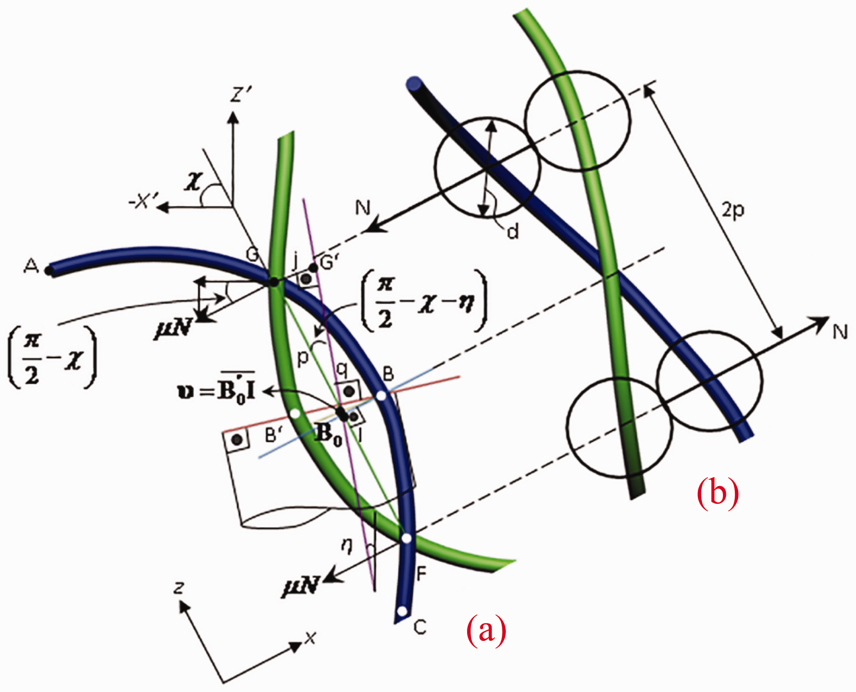
This couple can be written as

When the fabric becomes relaxed the positions of the points G and F in Figure 8 also change. It is assumed that these changes occur in a direction that is perpendicular with the

A line, which passes through the point B of the yarn axis of the loop and is perpendicular to the line that connects the points G and F, is defined. The point I is obtained in Figure 8, as the point at the intersection of the GF line and the newly defined line. The wrench arms of the friction couple
There is also a couple that is symmetrical about the x axis in Figure 8 as
This couple is, however, balanced by the yarn curvatures of the two interlocking loops.
It is thought that, because of the friction component
As a result of this section it can be said that, elliptical shapes had to be applied with eccentricity values e ≥ 0.85 instead of circular shapes, for the loop head of dry relaxed fabrics during the application of geometrical models
9
. The reason of this may be the friction force
The loop interlocking parameters q, p, j, υ and χ are too lengthy to be given.
Application of the model to a loop of E-glass fabric given in Part I as an example
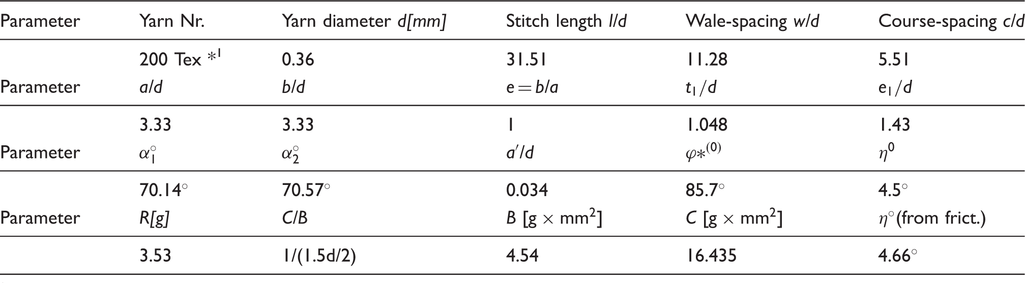
E-glass plain knitted fabric parameters obtained from the present model
Estimation of reaction force R
Reaction force R can be calculated using equation (9). This equation can be written again as

The parameter r in equation (14) is the radius of the loop head, a, and it was calculated in Part I, as also given in Table 1.
When all the necessary dimensional parameters from Table 1 are put, equation (14) gives the following equality

On the other hand, Lomov and Verpoest
11
worked on E-glass fabrics and obtained the following equalities between the yarn tex and the bending rigidities of E-glass yarns

Since a 200 tex E-glass yarn is used, the bending rigidity from equation (16) can be obtained as

The diameter of the yarn was taken as d = 0.36 mm. It should be noted that the diameter was calculated based on the number and the diameter of E-glass fibers in the yarn cross-section and by applying the open fiber packaging model. 12
Putting the bending rigidity obtained by the equation (17) and putting the obtained yarn diameter in equation (15), the amount of reaction force R is estimated as

Estimation of torsional rigidity C
When equation (4) is applied to the point B of the loop in Figure 7, the following equation is obtained

By putting the geometrical parameters given in Table 1 in equation (19), the bending moment at B is obtained as

At the same time, equation (10) gives the bending moment as

It should be noted here that this external bending moment at the end of the rod 
From equation (22)

On the other hand, Lomov and Verpoest
11
gave an estimated formula for torsional rigidity C as

When equation (23) is written in similar form with equation (24)

It is assumed that equation (25) should be used in place of equation (24), and thus equation (25) is a corrected version of equation (24).
By putting the yarn diameter and the bending rigidity (equation (17)) in equation (25), the torsional rigidity C is obtained as

The obtained mechanical parameters are also given in Table 1.
Checking the parameter η
The parameter η was obtained as η = 4.5° in Part I, using the minimum of yarn bending and torsional energies. In the present part, Part II, however, another way of calculation is given for obtaining the parameter η. It comes from the Assumption 4 as

This equality was used in the equalities given after equations (5) and (6) for obtaining equations (7) and (8). It is to be checked whether both the calculations give the same value.
Lomov and Verpoest
11
measured the coefficient of yarn to yarn friction for E-glass yarns and obtained the result as
Results and discussions
Results of the present model
As explained in Part I, a slack dry relaxed plain knitted fabric is defined as a dry relaxed plain knitted fabric with a tightness bigger than l/d = 20 for swellable yarns and with a tightness bigger than l/d = 16.75 for unswellable yarns.
The first result of the present mechanical model is that, for slack dry relaxed plain knitted fabrics equations (9) and (10) are applied. The angle η to be put in these equations can be obtained by the friction equation tan η = μ cos
Secondly, in the present model trapped torsions in the yarn arms of plain knitted loop are assumed. These trapped torsion energies balance some of the bending energies
Some other effect of friction is also considered during the creation of the mechanical model, which can explain why elliptical loop heads are obtained instead of circular heads during the application of any geometrical model to dry relaxed fabrics.
The created mechanical model is then applied to E-glass slack plain knitted fabric, as an exemplary application, on which the geometrical model created in Part I was also applied. The mechanical parameters such as reaction force R, torsional rigidity C etc. are calculated and given in Table 1.
Discussions on the previous models
As explained in Part 1, 1 most of the created models2–6 were applied to the wrong tightness points for swellable conventional yarn, i.e. the models were applied between l/d = 16….20 tightness region without considering yarn swellings. However, in fact, yarn swellings do change the geometry of the loop; therefore, those models created in the past did not fit the reality. Those models should have been applied to the tightnesses l/d ≥ 20 for the mentioned swellable fabrics, as their assumptions were more suitable for the slack tightness region. In addition to this argument, some more critical commentary on the previous models can be given as follows.
Hepworth and Leaf 5 assumed that no friction occurred in relaxed fabrics. At the end of their calculations, they concluded that there must have been course-jammings to hold the loop in force equilibrium state. However, the present model shows that, the force equilibrium state can be obtained by the help of frictional restrains without the need of course-jammings, at for example dry relaxed state.
Shanahan and Postle 6 gave a model in which they intended to use frictional restrains; however, their model could not explain the proper effect of friction.
Conclusion
Slack dry relaxed plain knitted fabric was defined in Part I as dry relaxed plain knitted fabric with a tightness bigger than l/d = 20 for swellable yarns and with a tightness bigger than l/d = 16.75 for unswellable yarns. It was also discussed in Part I that most of the technical fabrics could be considered in this slack fabric region. Therefore, the geometrical model given in Part I as well as the mechanical model given in the present part, Part II, are naturally beneficial for technical textile applications of plain knitted fabrics.
In this work, a mechanical model is created for dry relaxed slack plain knitted technical fabrics including 3D friction effect, based on the geometrical model given in Part I. After assuming the direction of friction and assuming a variable trapped torsion in the loop arms, the equilibrium of forces and moments are written using the elasticity theory of thin rods. The obtained results can be given as follows.
Using the geometrical parameters obtained in Part I, equations (9) and (10) give the mechanical parameters. These equations, in turn, use the friction equation, equation (11), to calculate the angle η. Therefore, the conditions of dry relaxed slack plain knitted fabrics can be considered as a friction induced stable state.
In the present model, trapped torsions in the yarn arms are considered as the geometry of 3D shape of loop given in Part I dictated. These trapped torsions balance some of the bending energies of the arm curves. Because of these two balancing energies (torsion and bending), the total energy levels of the loops become higher at their minimum energy conditions. It is believed that, because of these higher energy levels, the fabric is very sensitive to change its shape. If some differences occur between the energy levels of two rows or between the two arms of a loop, edge curlings or fabric spirality occur respectively in the fabric.
Some other effect of friction is also considered during the creation of the mechanical model, which can explain why elliptical loop heads are obtained instead of circular heads during the application of any geometrical model to dry relaxed fabrics.
The created mechanical model is then applied to the E-glass slack plain knitted fabric, as an exemplary application, on which the geometrical model created in Part I was also applied. The mechanical parameters such as reaction force R, torsional rigidity C etc. are calculated and given in Table 1.
Footnotes
Acknowledgement
The author would like to thank Assoc. Prof. Dr. Tuba Alpyıldız for her contributions in the initial drawings.
Declaration of conflicting interests
The author declared no potential conflicts of interest with respect to the research, authorship, and/or publication of this article.
Funding
The authors received no financial support for the research, authorship, and/or publication of this article.