
Abstract
This paper presents how the morphology of fibers is affected by CO2 laser treatment. The change in morphology of fibers induced by a laser affects the physical and mechanical properties of the fabric, such as water absorption, dye uptake, resistance to wrinkles and adhesion to other materials, etc. The morphology of laser-treated fibers was analyzed by scanning electron microscopy (SEM). Samples of cotton twill fabric, cotton/polyester blended twill fabric and cotton knitted fabrics with different yarn counts were studied before and after laser treatment. SEM images reveal different sizes of pores and cracks on the surface of cotton fibers. In the case of cotton/polyester blended twill fabric, the two types of fibers responded differently to laser treatment; the change in cotton fibers was slightly different from the SEM images of 100% cotton twill fabric. The number of pores and cracks on the fiber surface of cotton/polyester fabric was lower than that found in 100% cotton twill fabric. Polyester fibers melt and flow while cotton fibers are encased in resolidified polyester. For 100% cotton knitted fabrics, the thickest yarn with the lowest yarn twist exhibited the largest change when compared with fabrics knitted with lower yarn counts. The degree of change of fiber surface modification was enhanced with an increase of laser processing variables.
For a long time the surfaces of fibers have been modified by chemical means, such as oxidizing and reducing treatments, to improve the physical and mechanical properties of these fabrics, such as wettability, dye uptake, dimensional stability and resistance to wrinkles and shrinkage.1,2 However, these traditional chemical methods require rigorous process control and are prone to surface contamination, which may lead to undesirable and inconsistent surface changes, besides environmental problems caused by the use of large quantities of water and chemical agents. Increasing concerns about pollution and the protection of the environment raise the need for environmentally friendly methods for surface treatments.
According to the literature, there are some advanced technologies that provide fabric finishing treatment, such as plasma treatment, ozone washing, etc.3–8 However, ozone is produced during both treatments from pure oxygen. This powerful oxidant causes damage to mucus and respiratory tissues. This makes ozone a potent respiratory hazard and pollutant. 9 Laser treatment based on physical principles offers some advantages over conventional chemical methods. It enables precise surface modification in a short time. It is easy to apply and control, and is totally environmentally clean with no consumption of water and chemicals.10–14
Literature review
Since the invention of the first commercially available laser in 1960, 15 there has been a rapid growth of laser technology for industrial applications. In simple terms, lasers provide the ability for radiation to stimulate the emission of light, creating a situation in which light can be amplified. The light generated by lasers is very intense and contains a concentration of power within a very narrow beam in the electromagnetic spectrum regions extending from the near infrared through the visible to the ultraviolet. The visible region of the spectrum (where the human eye is sensitive) encompasses the wavelengths from 400 nm (violet) to 700 nm (red). Wavelengths from 400 nm to 10 nm are ultraviolet light; and above 700 nm to about 20 µm are the near-infrared wavelengths. The spectrum of electromagnetic radiation extends from the long wavelength radio waves to X-rays and gamma rays at the shortest wavelengths. The irradiation of polymeric materials by laser light generates characteristic modifications of the surface topography of polymers. The resulting surface properties may have an important impact on textile processing as they can improve the technical properties of fibers such as friction, wetting behavior, adsorption ability, reflection of light and adhesion properties of fibers or fabrics, which may include improvement in adhesion of dyestuff pigments in dyeing processes, etc. 16 This not only affects processing, but also defines textile properties in certain applications such as dyeing. 17 Besides the above applications, it has also been shown that lasers can potentially be applied to the design of the optical appearance of fibers through the modification of fiber surface topography. 3
Although some researchers have applied laser treatment to textiles, most of the studies have focused on marking textile surfaces and laser cutting methods. 18 Despite the fact that some studies have been conducted on laser engraving for the de-coloration of indigo dye present on fabrics, they have only focused on denim woven fabrics.19–21
In this study, the processing variables, namely resolution (a higher resolution (dots per inch, dpi), means that more laser spots are produced in an inch) and pixel time (a longer pixel time (μs) means that a laser spot is focused on one point for a longer time)10–14 used for laser treatment of two different types of semi-bleached fabrics, i.e., woven and knitted, are introduced, and the laser energy of each combination of variables is reported. Furthermore, the modifications of fibers of different semi-bleached fabrics are illustrated using scanning electron microscopy (SEM). The effect of laser processing variables on the surface changes of different fibers is also examined. In addition, the influence of yarn count and yarn twist of knitted fabrics on the changes to laser-treated fibers is also discussed. The morphology of the laser-treated fibers is analyzed by means of SEM. Samples of cotton twill fabric, cotton/polyester blended twill fabric and cotton knitted fabrics with different yarn counts before and after treatment are compared and their differences studied. This paper reveals how CO2 laser treatment variables affect the surface morphological structure of cotton and cotton/polyester blended fabrics.
Experimental
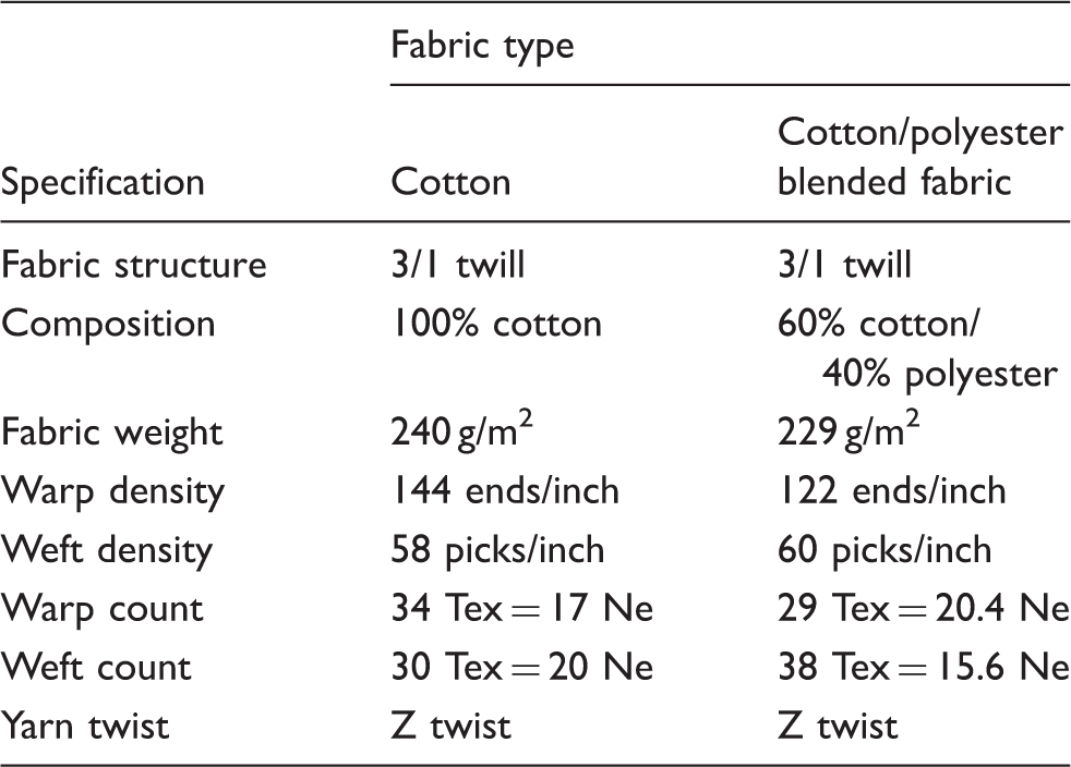
Fabric specifications of two woven samples
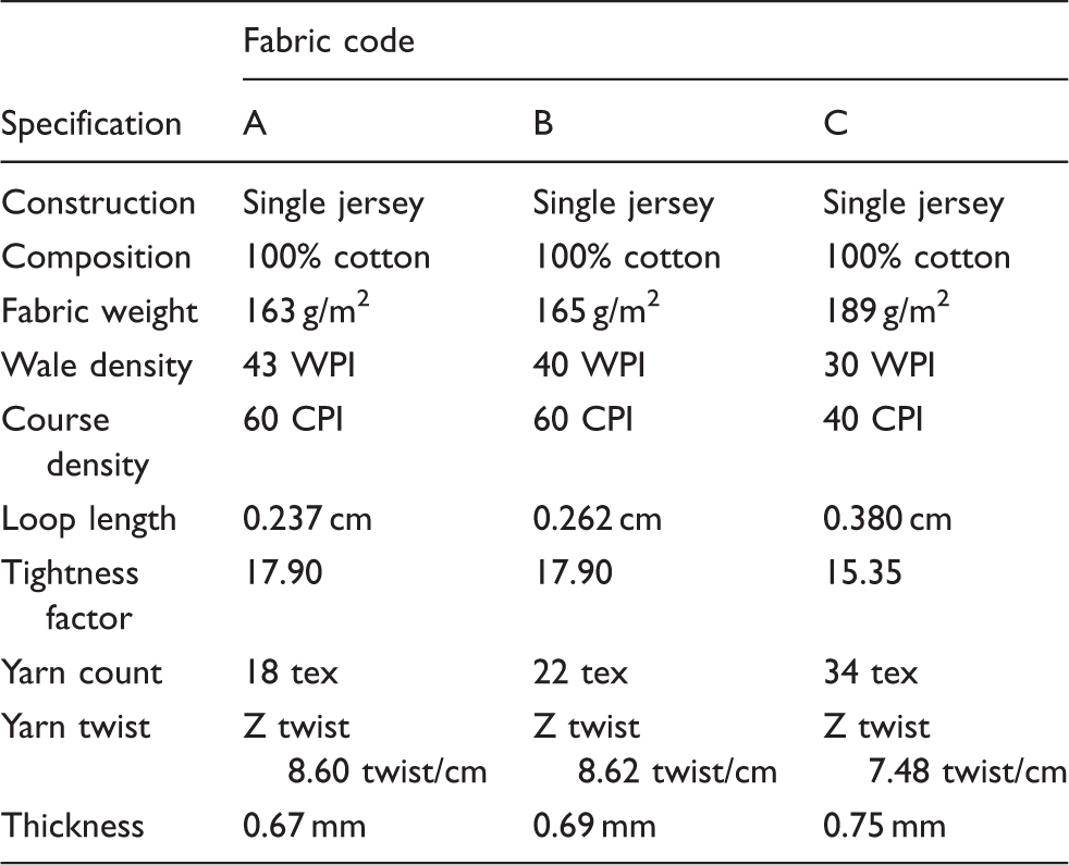
Fabric specifications of the three knitted samples
Pre-processing step
All of the semi-bleached samples were soaked with 30 ml/L acetone (reagent grade) (Sigma-Aldrich, Germany) for 10 min to remove any grease and dirt adhering to the surface.10–14 After washing, the samples were rinsed with water and hydro-extracted in a hydroextractor (Nyborg C290R Electrolux, Sweden) for 5 min. Lastly, the samples were dried in tumble dryer (Nyborg T4350, Electrolux, Sweden) for 15 min. All of the cleaned samples were conditioned under standard conditions of 65% ± 2% relative humidity and 21℃ ± 1℃ temperature for at least 24 h prior to all experimental and evaluation tests.
Laser irradiation and procedure
A commercial pulsed CO2 source laser engraving machine (GFK Marcatex Flexi-150, Spain) was used under atmospheric conditions coupled to an Easymark 2009 laser system (Rofin, Germany). The fabric samples were treated with two laser power density profiles with different combinations of laser processing variables, namely resolution and pixel time.10–14 The resolutions used were 28 dpi, 32 dpi, 36 dpi and 40 dpi with pixel times of 100 µs, 110 µs, 120 µs and 130 µs, a total of 16 combinations for profile 1. For profile 2, resolution was set to 52 dpi, 60 dpi and 68 dpi with pixel times of 110 µs, 120 µs, 130 µs and 140 µs, giving 12 combinations in total. A higher dpi means more laser spot are produced in one inch, and a longer pixel time (μs) means that the laser spot is focused on a point for a longer time. The laser treatment process as conducted on the samples is summarized as follows. A square pattern design 5 cm ×5 cm was created using Adobe Photoshop software (Adobe Systems Software, Hong Kong) on a computer (Windows 7 [Microsoft, Hong Kong]). The pattern was converted into gray scale. The pattern file was then input into the Easymark laser system and the parameters, pixel time and resolution were set. The sample was placed on a honeycomb cutting table, the laser engraving area of the sample was located and the position was adjusted as required. The pattern then appeared on the sample as created with the laser beam.
For laser power density measurement, a 842-PE hand-held Optical Power/Energy Meter (Newport Corporation, USA) was employed for measuring the laser power density of the different combinations of laser treatment process variables. Surface morphology of the treated samples was investigated by SEM (Leica Stereoscan 440, Cambridge Instruments, UK) with a resolution of 3 nm at 40 kV.
Results and discussion
Laser power density measurement
In this study, two types of fabrics were used, namely woven and knitted fabrics with different fiber compositions and fabric specifications. The fabric samples were treated with two laser power density profiles with different combinations of laser process variables, namely resolution and pixel time. Resolution is defined as a variable controlling the intensity of a laser spot in a particular area, and is expressed in terms of dots per inch. Pixel time is another variable, controlling the time that the laser head is positioned for each image point, in µs. Knitted fabrics were treated with profile 1; i.e., the resolution was set to 28 dpi, 32 dpi, 36 dpi and 40 dpi with a pixel time of 100 μs, 110 μs, 120 μs and 130 μs, with a total of 16 combinations. Woven fabrics were treated with profile 2; i.e., resolution was set to 52 dpi, 60 dpi and 68 dpi with a pixel time of 110 μs, 120 μs, 130 μs and 140 μs, giving 12 combinations in total.
Two profiles were used for the two different types of fabrics because woven and knitted fabrics have different structures. The structure of woven fabric is formed by interlacing warp and weft yarns whereas knitted fabric is created by interlooping yarns. Hence, the use of excessive laser irradiation energy can cause loops to break and result in laddering. This is unlike knitted fabric, which can be made by using just one yarn; whereas woven fabric is made up of at least two separate groups of yarns. The breaking of one yarn does not affect the whole fabric.
Furthermore, woven fabric is usually tighter than knitted fabric. As a result, woven fabric can be treated with a higher and wider range of laser energy irradiation. During the stage of adjustment and choosing the variables of resolution and pixel time, knitted fabrics were burned. Some holes were formed on the fabric surface when the resolution was above 40 dpi and the pixel time was above 130 μs.
The modifications to woven fabrics were more obvious when the resolution was above 52 dpi and then pixel time was above 110 μs. However, the fabrics were seriously damaged when the resolution exceeded 68 dpi and the pixel time was longer than 140 μs. Therefore, the ideal variables for laser engraving used on the knitted fabrics and woven fabrics in the present research range from 28 dpi/100 μs to 40 dpi/130 μs and 52 dpi/110 μs to 68 dpi/140 μs, respectively.
The laser power density of the corresponding combinations of resolution and pixel time used for both profiles was measured as depicted in Figure 1(a) and (b). The laser power density was enhanced in response to the increase in the level of resolution and pixel time. The figures also show that profile 1 had a lower laser power density while profile 2 had a higher laser power density. The laser power density of profile 1 ranged from 1.488 W/cm2 to 4.025 W/cm2, while for profile 2 it ranged from 5.525 W/cm2 to 11.963 W/cm2. Furthermore, Figure 1(a) and (b) illustrate the relationship between laser power density and laser processing variables, i.e., resolution and pixel time. It was expected that with the increase of laser process variables, the laser power density would be increased as shown in Figure 1(b). However, a zigzag relationship was obtained between the laser power density and laser processing variables in profile 1 as shown in Figure 1(a). Unlike the results shown in profile 2, the curve obtained was almost a straight line. The relationship between the laser power density and laser processing variables was positive linear for both profiles. For profile 1, the laser power density dropped in the case of 36 dpi/100 µs, 40 dpi/100 µs and 40 dpi/110 µs as shown in Figure 1(a), e.g., the laser power density of 36 dpi/130 µs was higher than 40 dpi/100 µs and 40 dpi/110 µs. It was concluded that besides proper control of various laser processing variables, the laser power density of the combination of variables had to be considered.
Relationship between laser power density and laser process variables (resolution and pixel time). (a) Profile 1; (b) Profile 2.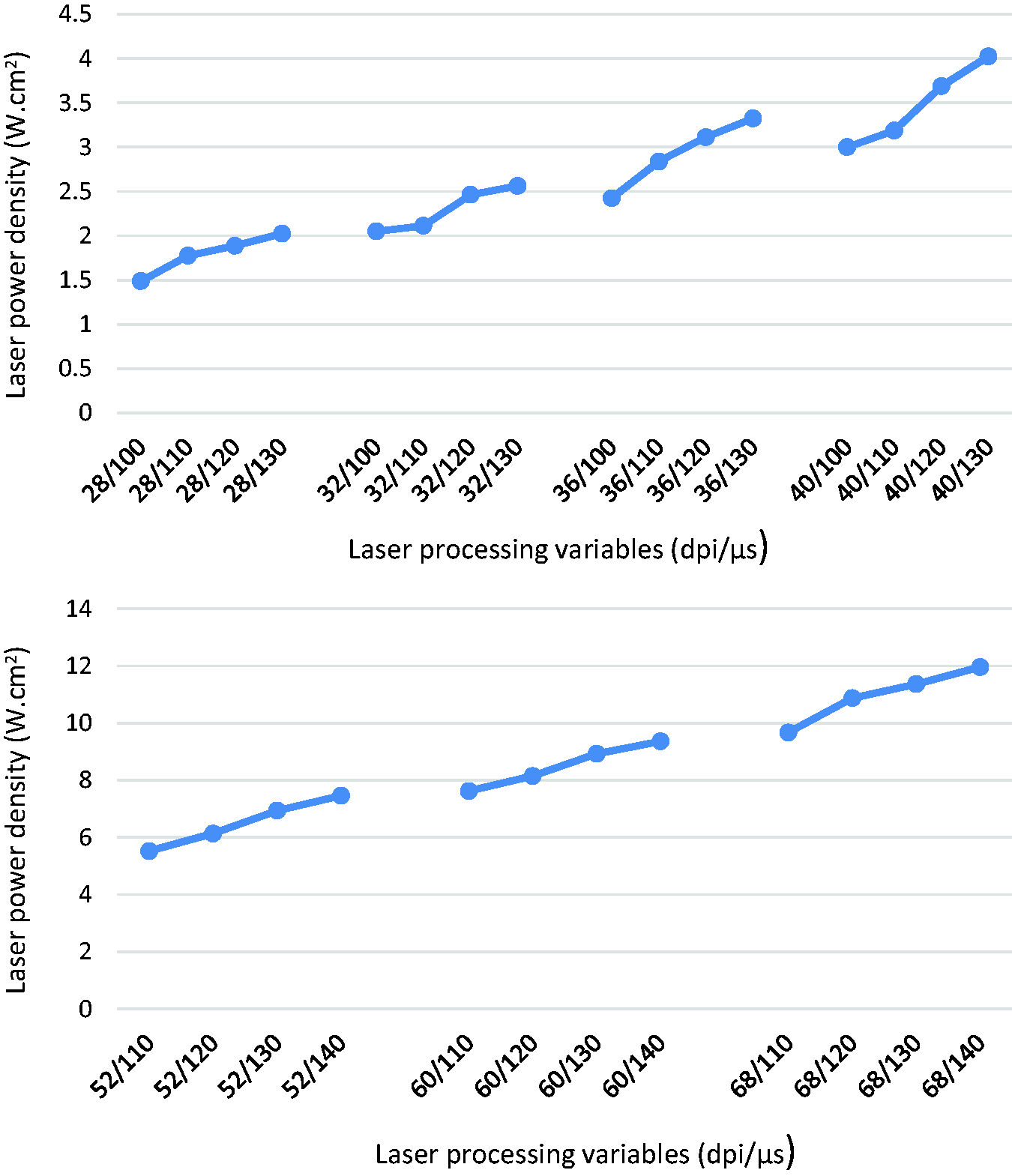
Scanning electron microscopy analysis
Woven fabric – cotton fabric
Figure 2(a) and (b) illustrate SEM images of the control sample, i.e., without laser treatment, at magnifications of 100 × and 3000×, respectively. The fiber surface is clearly smooth with convolutions. Wrinkle lines and some grooves parallel to the direction of the fiber axis are well defined.
Morphological features of the control cotton fabric. (a) 100×; (b) 3000×.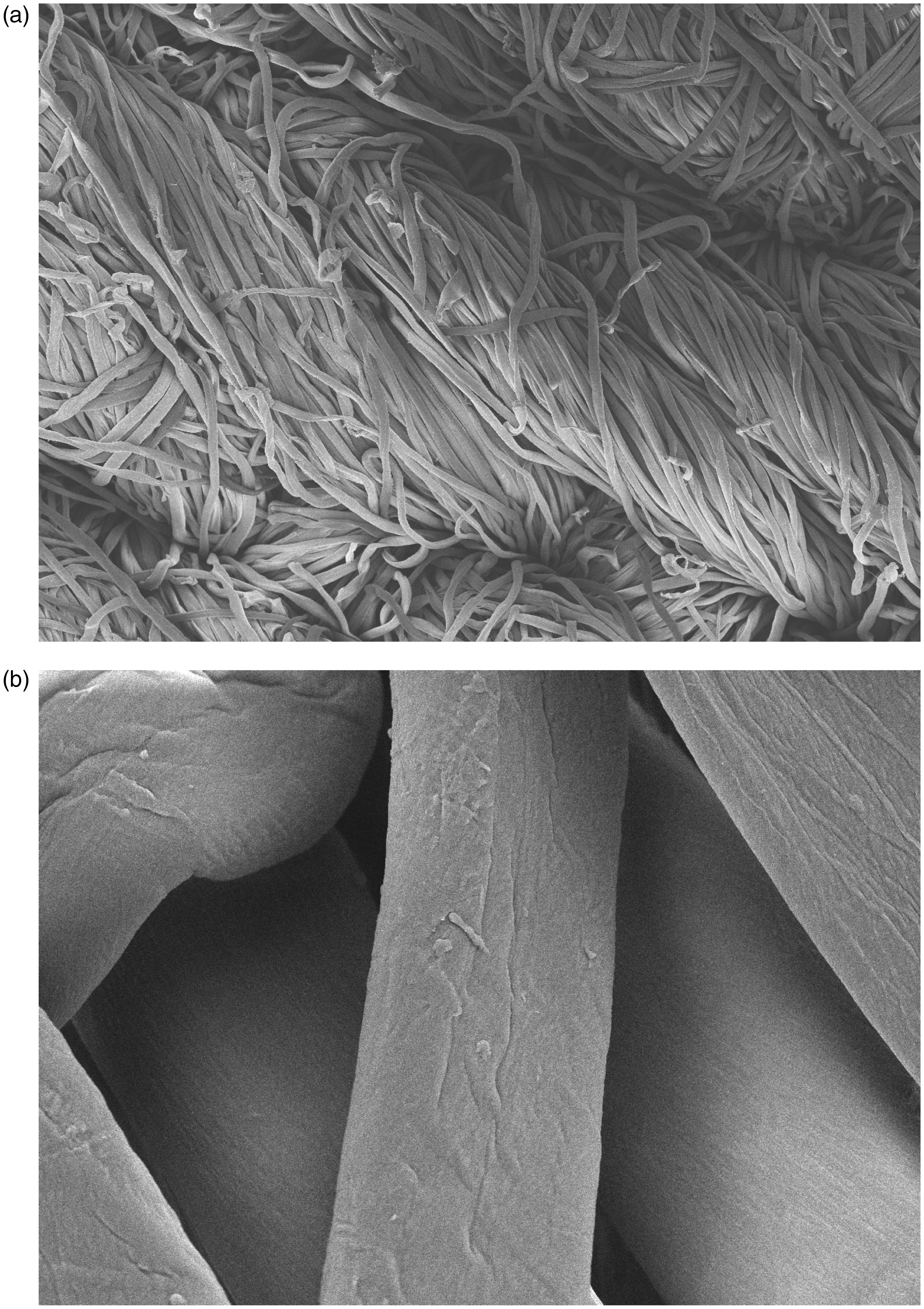
In order to study the effect of laser modification on cotton fibers in detail, the fabric treated with processing variables of 52 dpi/110 µs was magnified to 1500 × as shown in Figure 3. There were different sizes of pores formed on the fiber surface. Cracks were also found and the fiber surface was slightly peeled off, but the striations found on the control fibers had disappeared. The formation of pores was the result of dehydration caused by the absorption of CO2 infrared laser thermal energy during irradiation. The cellulose was degraded with swelling and bursting due to the high temperature from absorbing the thermal energy. Gaseous products such as water vapors and/or carbon dioxide were generated from vaporization due to the high temperature.19,22,23
Morphological features of the laser-treated cotton fiber with the variables 52 dpi/110 μs (1500×).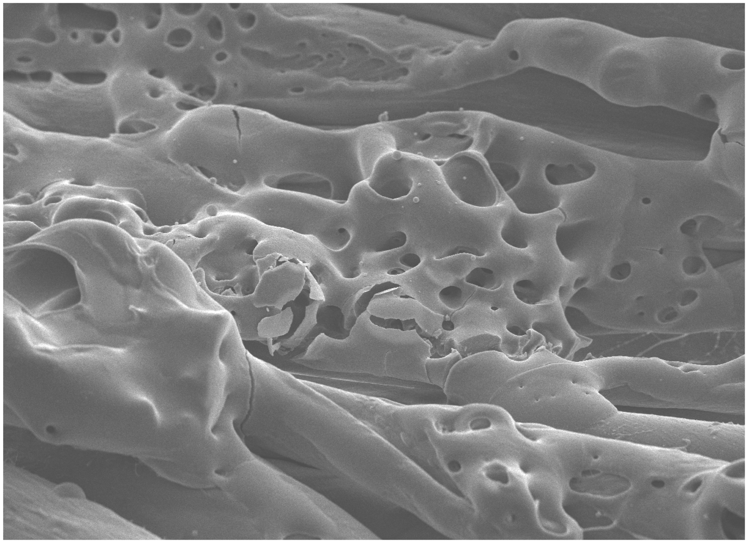
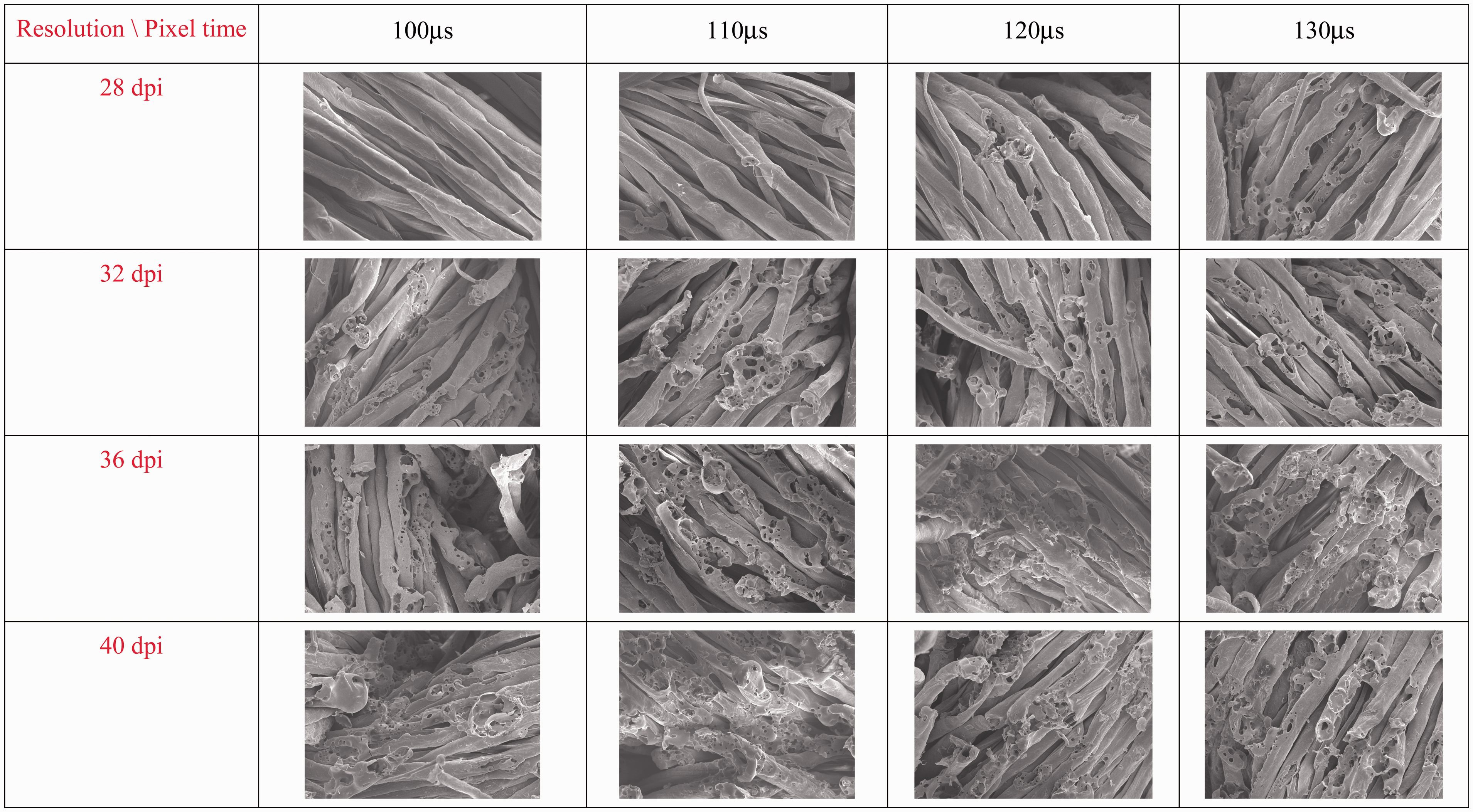
Figure 4 shows the SEM images (500×) of the laser modified cotton fibers with different energy intensities. Resolution increases from the bottom to the top, i.e., 52 dpi, 60 dpi and 68 dpi, while the pixel time increases from left to right, i.e., 110 µs, 120 µs, 130 µs and 140 µs. These micrographs show that the surface morphology changed significantly after laser treatment and the change was in proportion to the amount of radiation energy that they were treated with. Formation of pits on the fiber surface was prominent on all laser-treated fibers. The number of pits increased with the enhancement of laser processing variables. The SEM images also indicate that the laser irradiation on the fiber surface was unidirectional as the pits were formed randomly on the fiber surface. The alignment of fibers on each yarn for most of the variables could still be seen clearly.
Fiber surface modification due to different combinations of resolution and pixel time of the laser-treated cotton fabric (500×).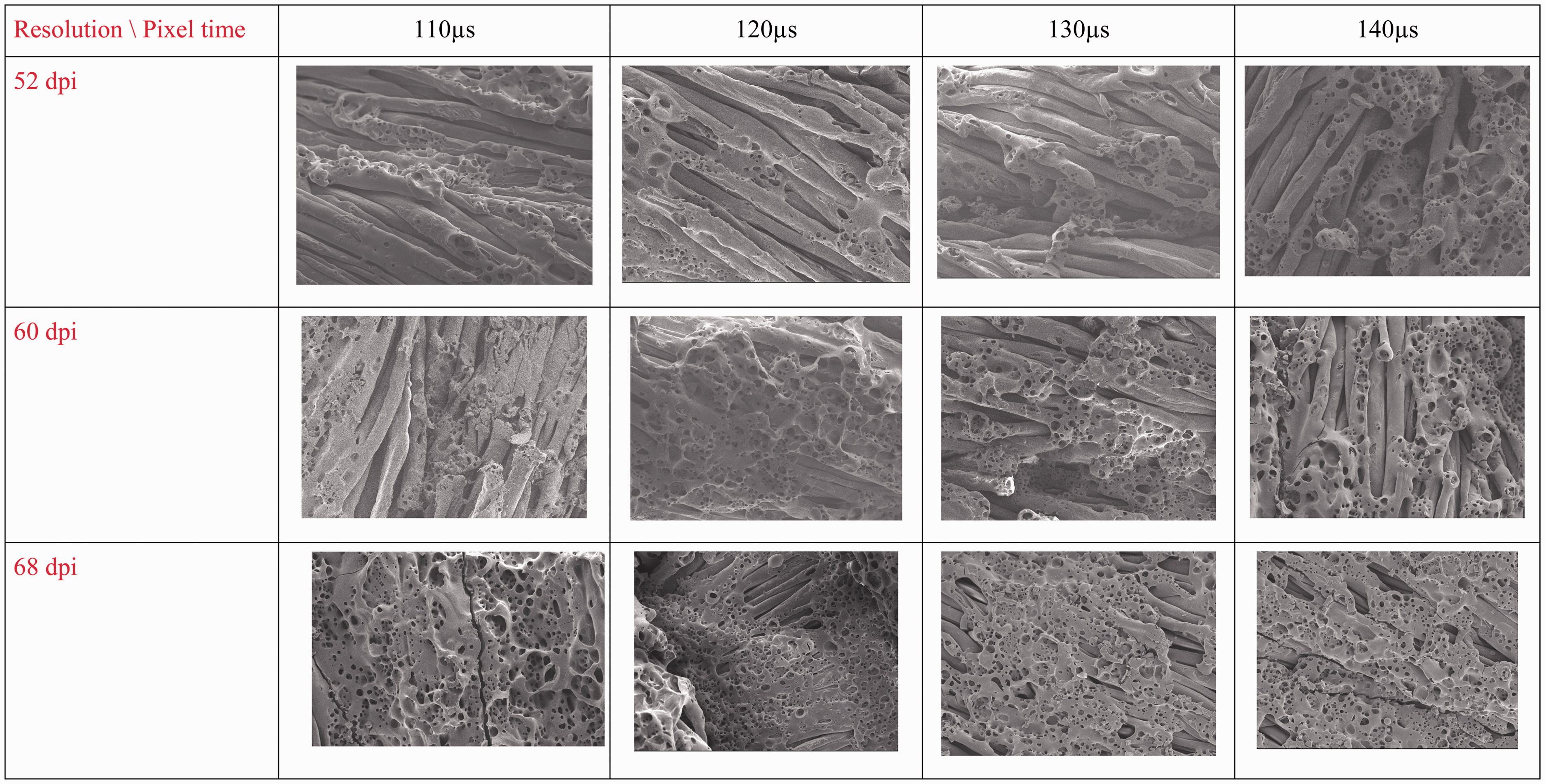
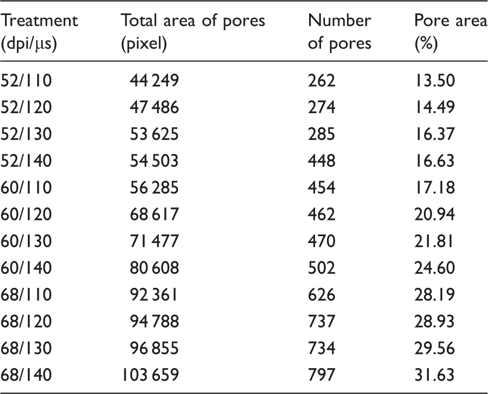
The effect of processing variables on the changes to cotton fiber was further studied in terms of pores size and density. The total area of pores and density in each SEM image of fabrics treated with different laser processing combinations as shown in Figure 4 were calculated using Adobe Photoshop as shown in Figure 5. The pore area is expressed in pixels, giving the total pixels in each picture as 327 680 pixels and a scale of 1 µm = 5.3 pixels as shown in Table 3. When the pixel time was increased from 110 µs to 140 µs for 52 dpi, 60 dpi and 68 dpi, the total size and density of pores was enhanced. Pixel time is defined as the time that the laser head is positioned on a particular area. A higher pixel time means a longer time and more energy focused on that area. As more energy is absorbed by the fiber with a longer time for laser head positioning on a particular area, the swelling and explosion of the fibers will be enhanced. As a result, more and larger pores are found when pixel time increases.
Area of one of the pores found on the cotton fiber laser-treated with 52 dpi/110 µs. Total area of pores and density on the laser-treated cotton fibers (1 µm = 5.3 pixel)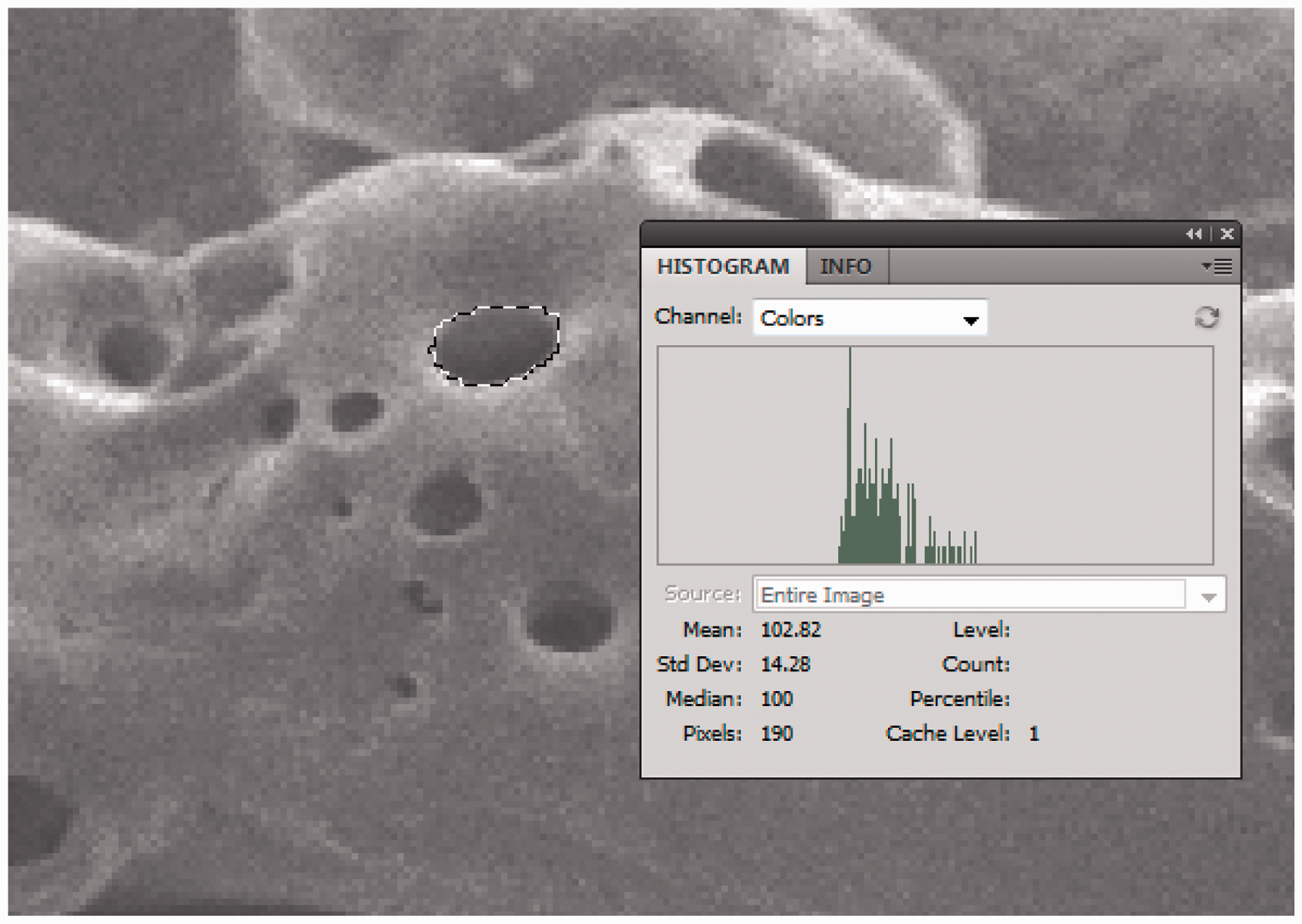
Changes occurring on fiber surfaces due to the increase of resolution from 52 dpi to 68 dpi are demonstrated in Figures 4 and 6(a) and (b). The increase of resolution resulted in the progressive loss of material. The fabric shown in Figure 6(a) and (b) was laser-treated at 68 dpi. The surface of the fiber was partially lost, producing a flat region due to the high etching effect. A higher resolution (dpi) means more laser spots are produced in one inch. As a result of continuous dehydration and oxidization, the fiber burst and shape of individual fibers became less obvious when compared to the fiber surface treated with lower energy; the degree of roughness was lower and surface area was less.
Morphological features of the laser-treated cotton fiber. (a) 68 dpi/120 μs (1500×); (b) 68 dpi/130 μs (3000×).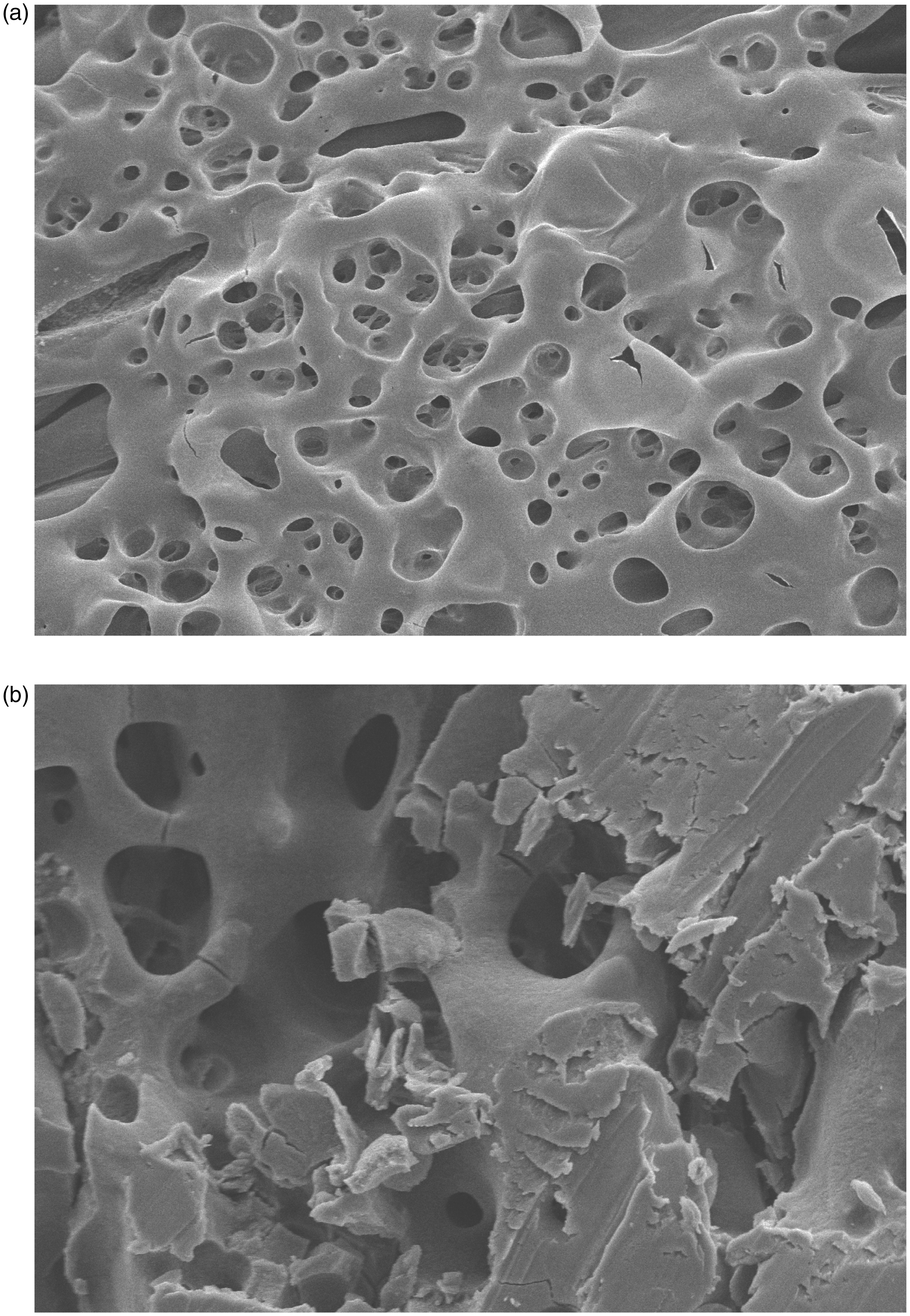
As well as the changes to the fiber surface, the depth of laser irradiation was also investigated. Figure 6(b) shows that for the fabric treated at 68 dpi/130 µs (3000×), small pores are found not only on fiber surface but also inside the large pores and inner parts of the fiber. This proves that laser irradiation is not only a surface treatment; with high enough energy the internal structure of the fiber can also be modified.
Woven fabric – cotton/polyester blended fabric
When cotton/polyester blended fabric was treated with laser light, different types of fiber would respond differently to the laser treatment. Based on the analysis of the SEM pictures of the control and treated cotton/polyester blended fabrics, a significant modification of the fiber surface was observed.
In Figure 7(a), the fiber surface of the control sample is even and smooth. When the SEM images of the control sample are magnified to 1500×, there are clearly two types of fibers present, as shown in Figure 7(b). There are some convolutions and wrinkles appearing on the cotton fiber surface while the polyester fibers have a clear and smooth surface.
Control samples of cotton/polyester blended fabric. (a) 100×; (b) 1500×.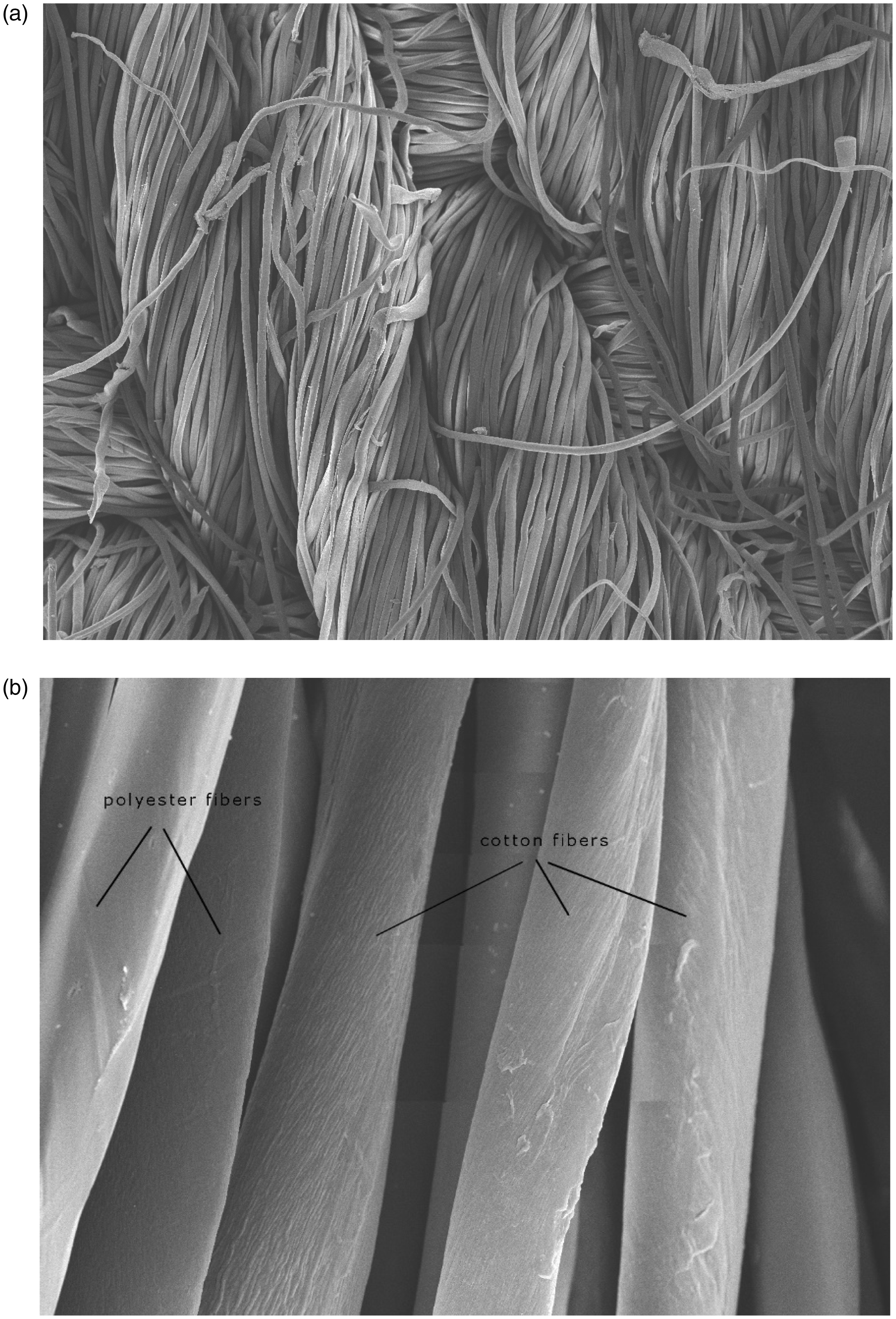
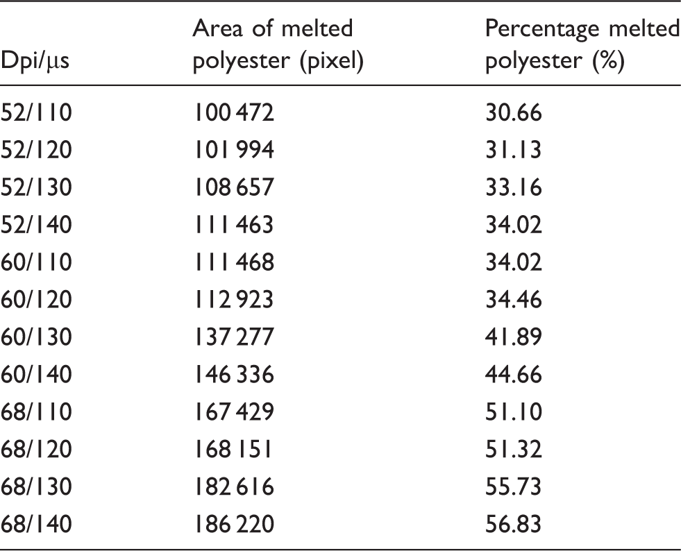
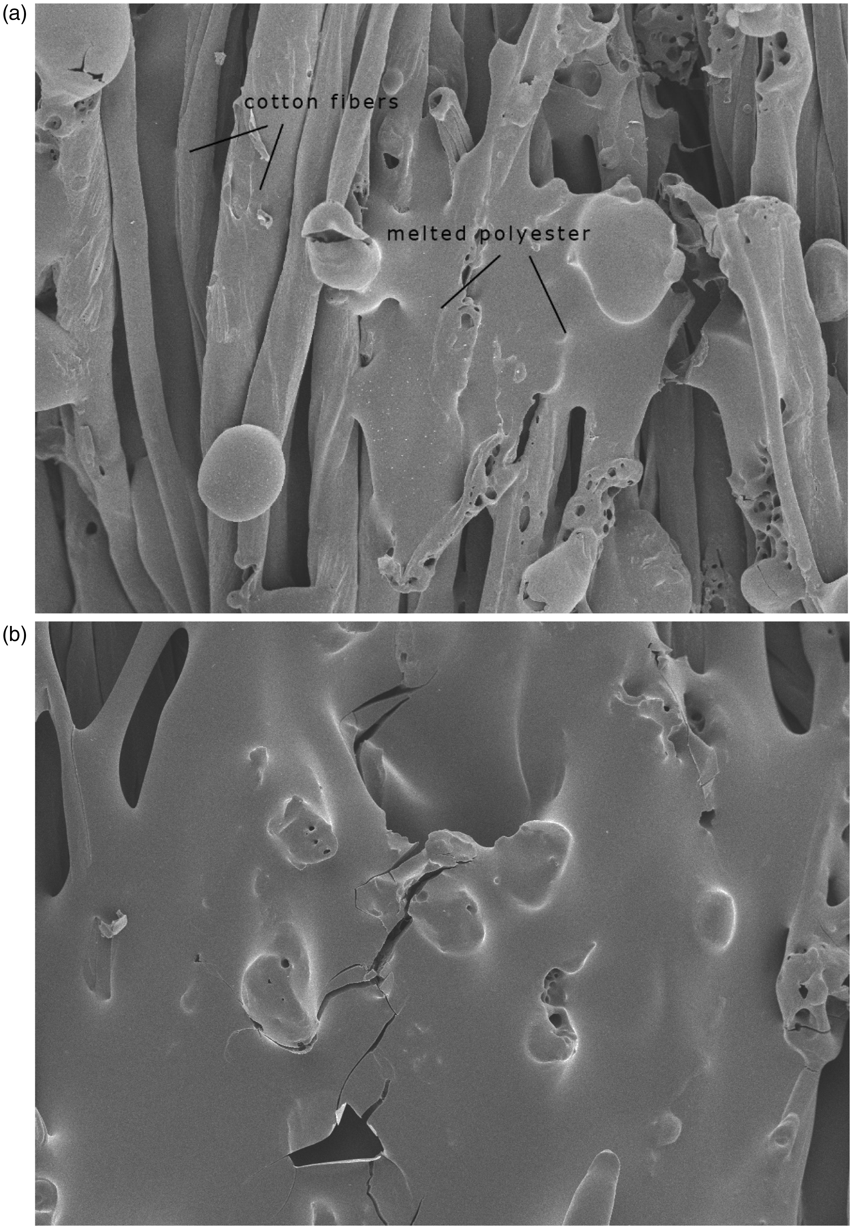
Figure 8 illustrates the SEM images of the samples treated with different laser processing variables. The percentage of melted polyester was calculated using Adobe Photoshop with the total pixels for each picture being 327 680 pixels, as shown in Figure 8. The results obtained are shown in Table 4. The SEM pictures show that craters are generated by laser irradiation and that grain shapes are formed on the fiber ends. As polyester is a type of thermoplastic fiber, the fiber ends protruding above the fabrics surface will contract and melt when subjected to heat.
24
During the laser treatment, heat generated from the laser beam causes the fiber ends to contract, melt and coagulate into these tiny polyester grains. Furthermore, the shape of individual yarns is less obvious when the resolution and pixel time are increased, resulting in extensive melting of the polyester. Polyester fibers flow, bridge and get fused together. When laser variables are increased to 68 dpi and 140 µs as shown in Figure 9(b), melting of the yarns is very severe, resulting in more flat regions when compared with the samples treated with lower laser energy, e.g. 52 dpi/110 µs as shown in Figure 9(a). The percentage of melted polyester fibers increased from 30.66% to 56.83% as shown in Table 4. The shape of individual yarns can hardly be seen and the pores are less obvious as the degree of melting of the fibers is increased from partial melting to the whole surface melting, which thus covers neighboring cotton fibers and also the pores present on the cotton fiber surface. Since CO2 laser light is an electromagnetic wave at a frequency of 10.6 µm, the photons transfer their energy to the molecular structure of the material, causing the material to heat up and vaporize.
25
Thus, during laser irradiation, the laser beam scratched the surface of the fiber and, at the same time, some fibers would melt and vaporize.
SEM pictures of the laser-treated cotton/polyester blended fabrics (500×). Area of the melted polyester corresponding to the combinations of different laser processing variables SEM pictures of cotton/polyester blended fibers. (a) 52 dpi/110 µs (500×); (b) 68 dpi/140 µs(500×).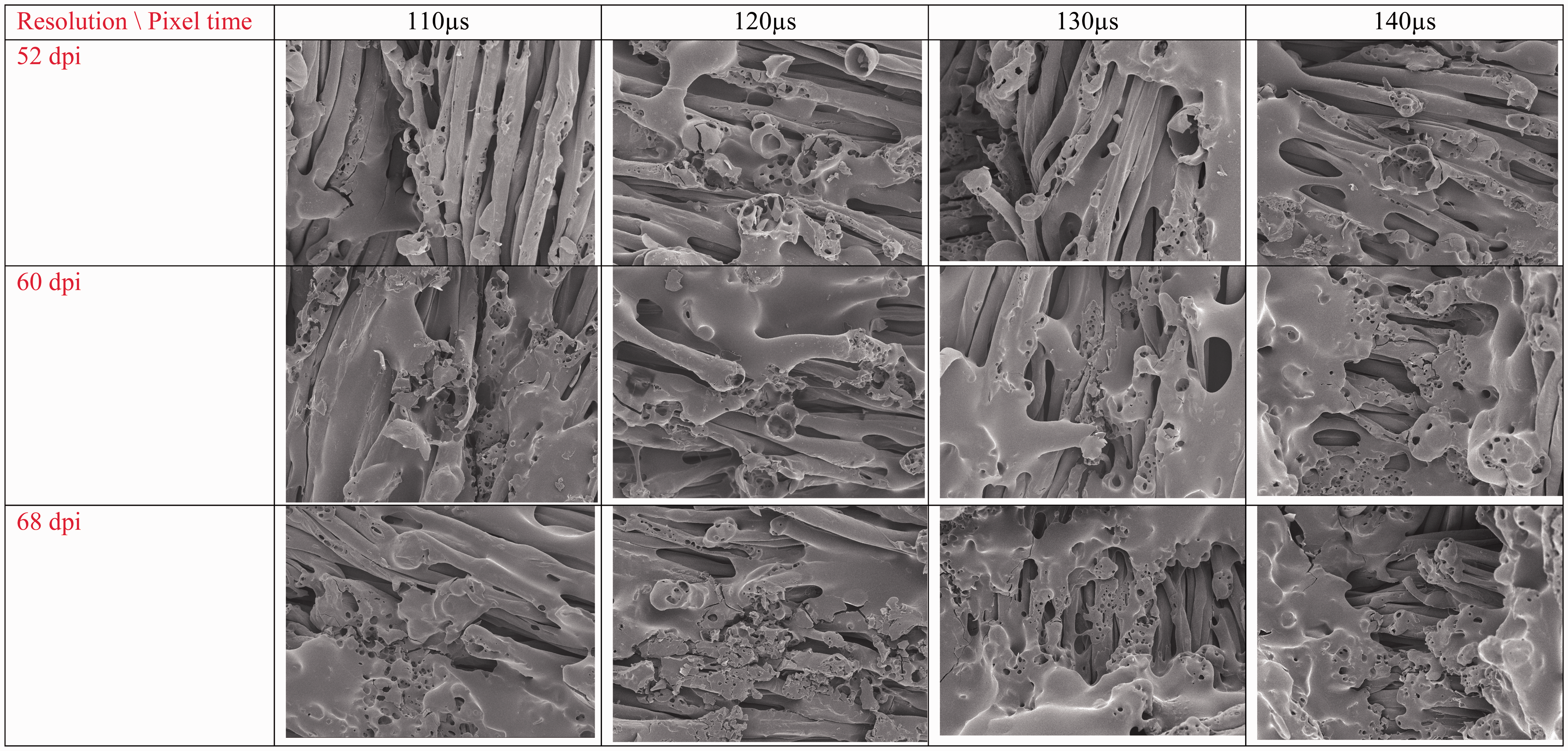
Knitted fabrics
According to Table 2, showing the specifications of the three types of knitted fabrics, it was clear that fabric C had the thickest yarn, followed by fabric B, and the thinnest yarn was found in fabric A. The yarn counts of fabrics A, B and C were 18 tex, 22 tex and 34 tex, respectively. Higher yarn count means that more fibers are found in the cross-section of the yarn. Another difference between these three knitted fabrics is expressed in terms of the tightness factor. Tightness factor is influenced by fabric density and loop length. Fabrics A and B had the same tightness factor of 18, and fabric C had a tightness factor of 15. Hence, fabrics A and B were tighter than fabric C. Tightness factor refers to the openness of the fabric; i.e., the higher the value, the fabric is less open, the fabric being tighter. As a result, air permeability is less in the fabric, and vice versa. The tightness factor generally ranges from 11 for slack fabric to 19 for tight fabric. Fabric with a tightness factor of 15 is generally optimum and preferable. Lastly, the yarn twist of the three knitted fabrics was different. Fabrics A and B had a higher yarn twist value than fabric C, indicating that the yarns of fabrics A and B were twisted more intensely than fabric C. Hence, the yarns of fabrics A and B were thinner than fabric C. The effect of the difference in fabric specification of knitted fabrics upon the effects of laser treatment was studied using SEM.
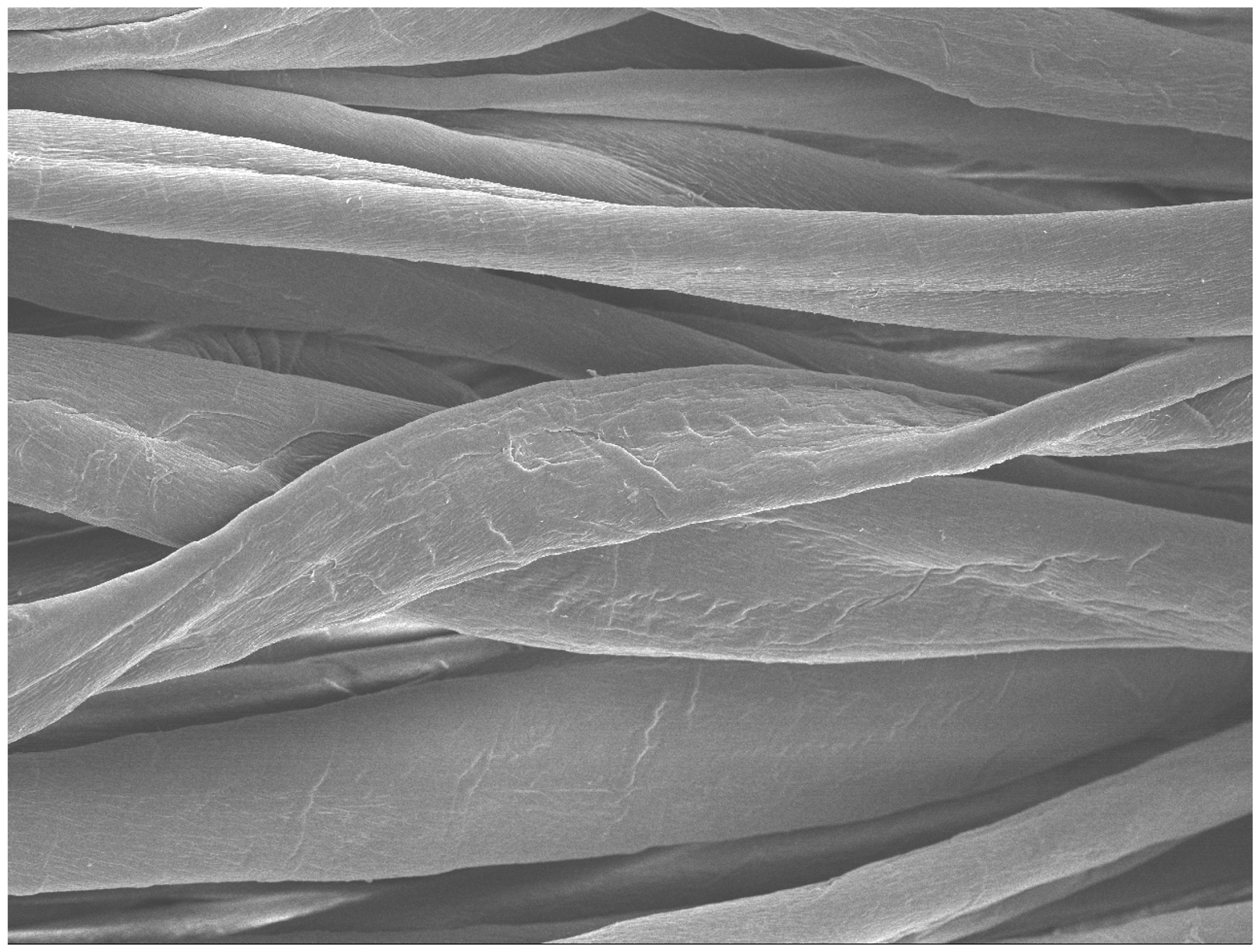
The original cotton fabrics A, B and C, which are depicted in Figure 10(a) to (c), respectively, and the results for the laser-irradiated samples (fabric B) are shown in Figure 12 for various laser energies. All of the control samples have a smooth fiber surface, while the cotton fiber surface has convolutions (Figure 11), while the laser-treated samples as shown in Figures 11 and 12 have tiny grooves and microscopic cracks on the fiber surfaces. Exposure of cotton fabric to CO2 laser light causes carbonization.
22
As the CO2 laser is a type of infrared laser, material is heated up from the thermal energy of the laser, thereby causing thermal damage, resulting in carbonization. The effect of carbonization is enhanced as resolution and pixel time are increased. Hence, craters formed on the fiber surface become more distinct when the resolution and pixel time are increased.14,22
Morphological features of control fabric. (a) Fabric A, 100×; (b) fabric B 100×; (c) fabric C 100×. Morphological features of control fabric B, 1000×. Morphological features of laser-treated fabric B (500×).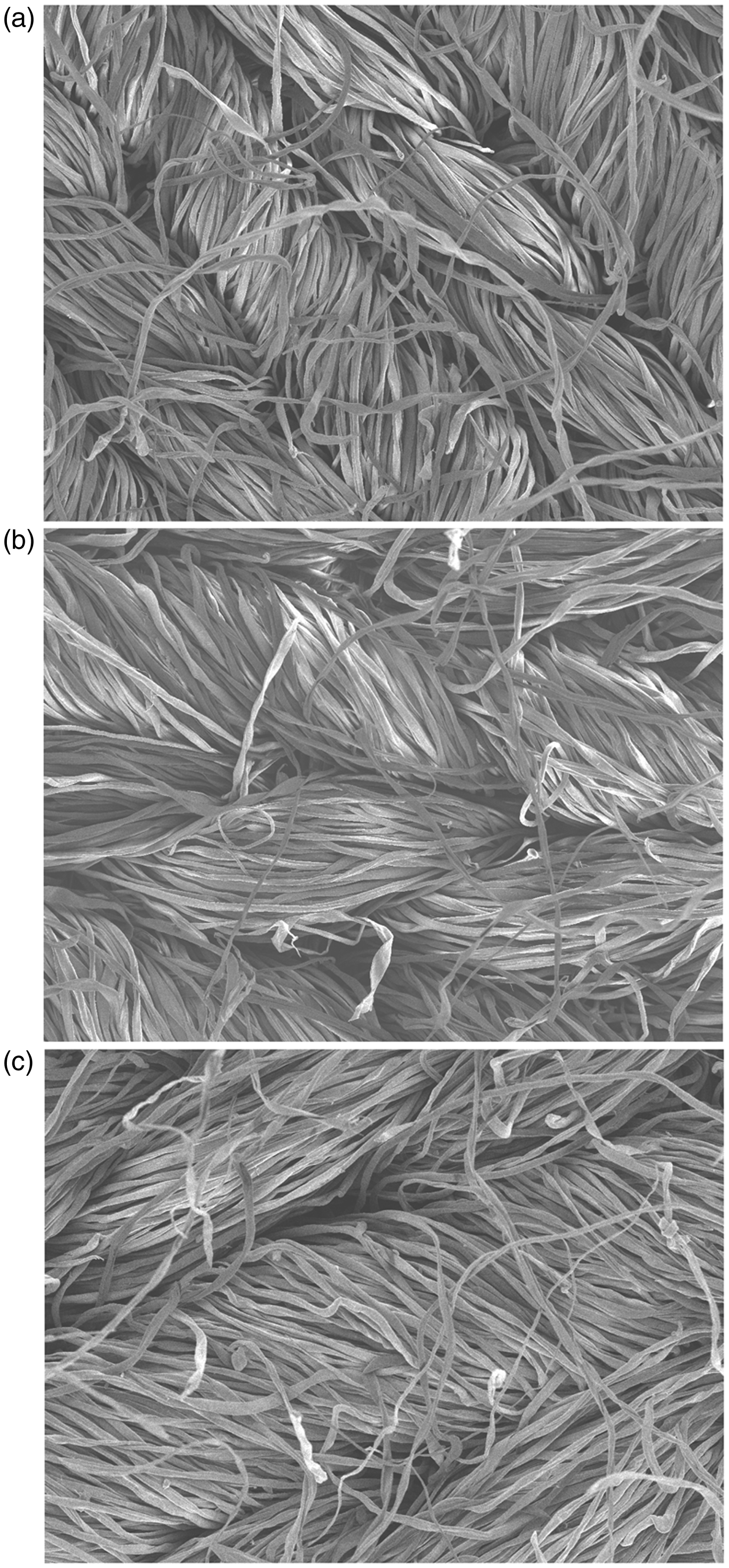
To examine the role of fabric specification affecting the result of laser treatment, the morphological changes to fabrics A, B and C after exposure to laser treatment with the process variables of 40 dpi and 130 µs were compared, and are shown in Figure 13. Fabric C suffered the most serious damage to the fibers, followed by fabric B and fabric A. Fabric C had the highest density of pores, while the size of pores was similar for all the three fabrics. It was postulated that the highest density of pores found in fabric C was due to it having the highest yarn count. This meant that the yarns used for fabric C were the thickest and had the highest number of fibers in the cross-section of the yarn. In addition, the yarn twist of fabric C was the lowest among all the fabrics. As a result, fibers within the yarn were more loosely packed than those of other fabrics. Therefore, when the laser beam hit fabrics A, B and C, a larger number of yarns per square inch was treated in fabrics A and B. However, for fabric C, the yarns were thicker and there were fewer yarns. Hence, a laser beam with the same resolution caused more pores to appear on the same yarn. Based on this result, it is concluded that the number of pores created on the yarn is affected by the yarn count and yarn twist.
SEM pictures for different laser variables treated at 40 dpi/130 µs (200×). (a) Fabric A; (b) fabric B; (c) fabric C.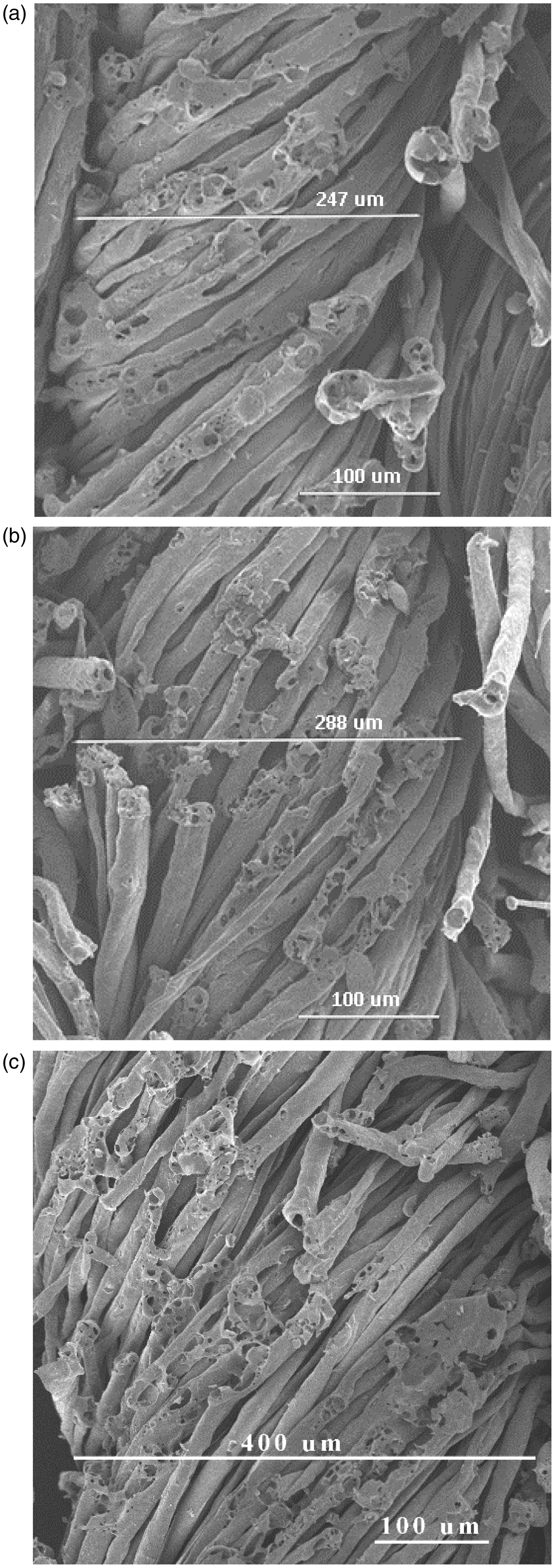
Conclusions and future work
Morphological analysis allows the estimation of the characteristics and size of microscopic changes in fibers as shaped by different laser energies. Experimental results reveal that the change of fiber surface varies according to the fiber material. Furthermore, the degree of morphological change depends on different laser variables. Increase of resolution and pixel time enhances the laser power density, and so the change of morphology becomes more pronounced.
As for cotton material, pores and cracks were created on the fiber surface. The density and size of pores and cracks were increased with an enhancement of laser intensity. In the case of cotton/polyester blended material, grains were coagulated at the fiber ends. With an increase of the laser processing variables, the pores that were formed on cotton fibers were covered by the melted polyester fibers due to the thermal effect of laser irradiation. As a result, uneven flat regions were created. With regard to the knitted fabrics treated at lower laser intensities, the change was not as large as that in woven fabrics. There were tiny grooves, and microscopic cracks appeared on the fibers. With an increase of resolution and pixel time, the changes became more distinct. In addition, even when the laser variables were the same, there were different results. The number of pores found on yarn was the largest for a higher yarn count and lower yarn twist. As a result, the number of pores created on the yarn was affected not only by the laser processing variables but also by the yarn count and yarn twist.
In conclusion, different fiber surface changes can be created with the proper control of various laser process variables. Also, fabric specifications influence the effects of laser treatment.
In the future, it is recommended that the surface chemical composition of the laser-treated cotton fabric should be studied. Also, the relationship between the surface chemical composition and the laser process variable would be an interesting study area.
Footnotes
Declaration of conflicting interests
The authors declared no potential conflicts of interest with respect to the research, authorship, and/or publication of this article.
Funding
The authors disclosed receipt of the following financial support for the research, authorship, and/or publication of this article: This work was supported by The Hong Kong Polytechnic University (RPTV).