




Abstract
The impact force loss behavior of flocked energy absorbing materials (FEAM) was experimentally studied in the context of double-side flocked FEAM element layered structures. A ball drop test determined the force loss per cent (FL%) properties of various assembled panels. This study showed that: (a) FEAM layers are most effective when used in multiple layer configurations. (b) When fabricating multi-layer two-side flocked FEAM layer configurations, a film or fabric divider sheet should be placed between adjacent flocked layers to prevent the flocked fibers from intermeshing with each other during compressional deformation. (c) FEAM elements perforated with 6.4 mm (¼”) diameter holes, 12.7 mm (½”) off staggered centers, exhibit a higher FL% per areal density compared to non-perforated FEAM panels. (d) Promising improvements in FL% properties are found by sandwiching either foam or spacer fabric between two FEAM layers. These three-layer structures are found to have higher FL% values than individual foam or spacer fabric components. A possible synergistic effect might be operating. (e) Low strain rate (5 and 50 mm/min) compressional load deflection rate data on combination FEAM/ vinyl nitrile foam/FEAM layers have shown that the initial ‘hump’ in the foam’s stress–strain curve is eliminated. FEAM layers and their foam and spacer fabric combinations should lead to creating effective impact energy absorbing pads for sport, military and civil servant applications.
The primary function of all textile fabrics is to provide the human body with protection from the adverse and changeable effects of our natural and service-function environments. Textiles shield humanity from excessive heat in hot weather, provide warmth in cold climates and shield us from the sun’s harmful radiation. Added to these traditional uses, fibrous textile fabrics are also used to protect the human body from excessive mechanical abrasion, wear and tear. There is also a particular interest in the use of protective textile structures that serve as cushioning materials during repeated mechanical bodily impacts.1–3
Previous researchers have looked into various types of fabrics and measured their energy absorbing capabilities. For instance, Liu et al.4,5 studied the quasi-static and the dynamic behavior of warp knitted spacer fabrics (WKSF) and compared them to a polyurethane foam’s impact absorbing behavior. The study by Shim et al. 6 analyzed different types of fabrics and their suitability for flexible ballistic armor applications. These fabrics were analyzed through tension tests and an approach involving the numerical modeling of viscoelastic materials. It is also known that interlocking woven multi-layer fabric structures are used in ballistic applications to absorb shrapnel and debris strikes during military action.7,8 The work by Arabzadeh et al. 9 numerically modeled spacer fabrics to describe their behavior under compressional impact loads. In the study by Qiao et al., 10 the impact mechanics of high-energy absorbing materials are reviewed. Also, numerical models and computer simulations for various types of mechanical impact are discussed. Lastly, in the research by Li et al. 7 FEA models are created to analyze woven composites under ballistic impacts. All these reviewed studies have employed well-established impact mechanics testing and modeling methodology to analyze traditional energy absorbing materials. However, none of these reviewed publications address other important properties of the impact energy absorbing (IEA) materials such as attaining high energy absorption at low areal density. Material flexibility and breathability are also material properties of interest for such materials. To this end, this paper introduces a new form of textile material structure that has the potential of being used as a media for protecting or mitigating the injurious effects that mechanical impacts may have on the human body. This new textile structure employs the spring action of the end-wise compressional bending behavior of the nominally upright short individualized monofilament fibers of a flocked surface. It is expected that flock energy absorbing material (FEAM) structures could address some of the shortcomings of traditional IEA textiles by developing them into very effective IEA materials having low areal density, high flexibility and three-dimensional (3D) breathability.
Presently, there are several classes of textile materials that are used in impact energy absorbing applications, namely thick layered fabrics, felt, spacer fabrics and now introduced in this paper, flocked surfaced FEAM textile structures. All these various textile materials absorb mechanical impact stresses by different mechanisms depending upon the textile fiber’s geometry and orientation relative to the direction of the impacting deformation force. The IEA mechanisms for these materials are now reviewed.
FEAM impact energy absorbing structures: (a) Sketch of single-side flocked FEAM; (b) sketch of double side flocked FEAM, (c) Cross-Sectional Photomicrograph of typical FEAM structure [FX202-2D used in this study] (20 X); actual shown thickness is 5 mm (0.20”).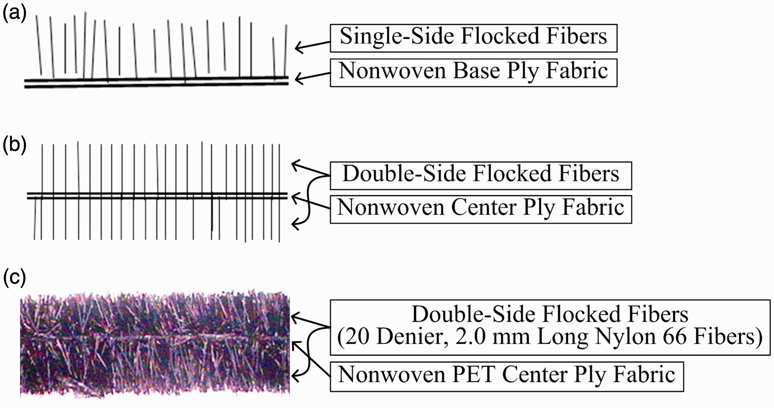
A general description of this IEA mechanism was recently studied by finite element analysis (FEA) methodology.12,13 Here it was learned that there are three strain energy deformation phases operating when a FEAM containing IEA pad assembly is fully compressed by an impacting projectile. The
FEAM structures have enormous design versatility because of the many choices available for a flock fiber’s material type, fiber geometry such as length, denier and cross-sectional shape and applied flock density (number of fibers/area). The structure and weight of the central support ply are also an important property maintaining parameter. However, it is the compression bending/buckling of these upright oriented flock fibers that causes the smooth, damped spring-like IEA action that occurs when these flocked layers are compressed. Notably too are the multitude of the loose, pointing upright flock fiber ends which can also contribute to the IEA action. This flock fiber free-end effect would be frictional. It would most likely be operating during phase 2 of the IEA deformation mechanism described. It is conceivable that the frictional dynamics and ‘fretting’ of this multitude of fiber ends could contribute significantly to the IEA mechanism of FEAM elements. This fiber-end frictional effect on the material’s IEA mechanism has not yet been fully investigated.
Other features of FEAM elements are worthy of mention, such as the open spacing between the flocked upright fibers that gives FEAM an inherent lateral two-dimensional (2-D) breathability. In this paper, the material impact energy absorption properties have been measured using a ball (spherical projectile) drop test as an IEA laboratory screening tool. One typical FEAM configuration was chosen for this present study; 20 denier, 2 mm long nylon flock fiber bonded to both sides of a thin, lightweight polyester (PET) nonwoven center ply (Figure 1). Some fundamental properties of FEAM material and multi-layered structures are reported and discussed. Single and multiple (stacked) FEAM element assemblies are experimentally investigated regarding their apparent IEA properties. In this paper, FEAM layer materials were experimentally evaluated for the purpose of evaluating their potential function as a new type of textile-based head and body apparel protection IEA padding material. 12 In additional studies, FEAM’s ball drop force loss per cent (FL%) properties are compared with other more conventional energy absorbing materials such as foam, spacer fabrics and felt. It is important to know how the FL% properties of FEAM materials compare to these traditional IEA materials. Furthermore, the FL% properties of combining layers of FEAM with foam, spacer fabric and felt ply layers are reported and discussed.
Experimental details
Sample materials
Description of FEAM material panels and fabrication assembly components

In the course of this work a nomenclature scheme describing FEAM structures has been devised. Here the FX202-2D notation refers to ‘FX’ = Flocked Experimental, ‘20’ refers to a 20 Denier flock fiber used; ‘2’ designates nylon as the flock fiber type and ‘D’ refers to a Double-side flocked panel. The added ‘P’ represents that the FEAM panel has been perforated with holes.
Description of foam and felt materials

Memory foams are the type of polyurethane foam that easily compress into a deformed shape. When the stress is released, the foam will more slowly recover from its deformation. The foam returns back to its original shape – it has a ‘memory’.
Descriptive properties of spacer fabric materials a

WKSF Fabrics, for knitting machine specifications, refer to Liu 2012 4
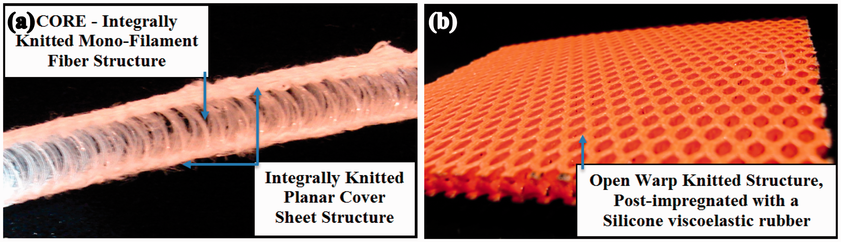
Photographs of two spacer fabric structures: (a) View of WKSF-C Cross-Section Showing Monofilament Fiber Core Spacer Structure and (b) Close-up Photo of DEFLEXION® (Dow Corning) Silicone Rubber Impregnated WKSF.
Ball drop test
A material impact property screening test was developed for evaluating the IEA properties of FEAM and other traditional and experimental pad materials. The screening tool was in the form of a ball drop test (BDT). BDTs are often used by the foam industry to demonstrate the IEA properties of their foam products. There is no official ‘standard’ for the BDT used in this study. The BDT apparatus was designed and developed for the sole purpose of providing the project with a IEA measurement tool for the reported study. Here, the BDT uses a 1.7 kg, 12.7 cm (5”) diameter (duckpin) bowling ball that is dropped from a 100-cm height (see Figure 3) onto the test panel. The geometric parameters of the ball chosen in this study were fixed by the dimensions and weight of a typical duckpin bowling ball. Furthermore, a spherical projectile is the only projectile with the proper symmetrical shape that could fit the role of a free-falling mass striking a test panel. The estimated ‘hit’ velocity of the striking ball was estimated to be 4.4 m/s (14.5 ft./s). Other size and weight balls are available for such tests (e.g. Bocce ball and the smaller Field Hockey ball) but in some preliminary tests it was decided to use the duckpin bowling ball for all the BDTs herein reported. During the ball drop process, force–time signals are electronically recorded such that a FL% can be calculated for each impact.
Schematic diagram of ball drop impact testing apparatus.
In the actual test, 9 cm × 9 cm (4” × 4”) FEAM panels are placed on a PASCO (Roseville, CA 95747) force platform; 12 a force–time mechanical impact event recording instrument. The impulse pattern data are acquired using Pasco’s USB interface that is processed and displayed by Capstone software obtained from PASCO. The tested panels were not secured to the force platform. A truss frame structure guides the bowling ball so that it strikes the test panel at a set location. Ball-strike impact (force–time) signals from the PASCO force platform are recorded on an interfaced computer. All reported data are an average of at least five replicate measurements. The measured ball-drop parameters are calculated and reported as:

FL% represents the measured percent impact force lost through the IEA test material. The FL% data obtained from these BDTs are meant to be ‘screening’ tests that represent the ‘relative’ IEA properties of the tested FEAM material panels. Physics principles define energy, or work, as the force required to move a mass a certain distance. Therefore, energy will only be directly proportional to force when the deformation distance during the ball drop strike is constant for all tests. In this paper, it is assumed that the compressional deformation depth during the tests are all very similar. With this assumption, the use of impact energy absorption and impact force loss terms are used somewhat interchangeably.

Results and discussion
Experiments were carried out to assess the impact properties of single and multiple layer FEAM element assemblies. Several variations of flock and FEAM configurations were first evaluated in the context of their overall FL%, FDI and IF performance. Ball drop impact test data were obtained for various FEAM assemblies: (a) number of layers, (b) inclusion of divider fabric between FEAM elements for multiple FEAM layer test panels, (c) hole perforation and (d) non-barbed needle punching. One, two, three and four layered FX202-2D and FX202-2DP were assembled by wrapping them with a micro-suede cover fabric (see Table 1), and then perimeter sewn.
Varying the number of FEAM layers
Ball drop test (BDT) results for FX202-2D FEAM configurations

All FEAM panels have been needle punched unless specified otherwise.
All samples were micro-suede fabric wrapped and perimeter sewn.
FL% Base hit value: 795.8 +/- 15.8 N (no test sample on PASCO force sensor platform)
No divider fabric between contiguous flock surfaced FEAM layers.
It is observed in (Figure 4(a)) that FL% increases 11, 14 and 16% per additional layer for FX202-2D-ND, FX202-2D-DP and FX202-2D-DNP panels, respectively. A similar trend is observed for the FX-202-2DP panels (Figure 4(b)). Comparing the FL% results of the FEAM materials with perforated holes (FX201-2DP) with the FX202-2D (no holes) in Table 5 we find that the hole perforated FX202-2DP produced slightly lower overall FL% values compared to the non-hole perforated FEAM. This can be attributed to the fact that FX202-2DP configuration’s surface has about 25% fewer flock fibers available to participate in the material’s compression/flock fiber bending IEA mechanism compared to the non-perforated FEAM material. Additionally, Table 5 indicates that the FDI of these FEAM panels decreases as the number of stacked FEAM layers increases. Additionally, Table 5 shows that the force FDI of these FEAM panels decreases as the number of stacked FEAM layers increases.
Effect of the number of layers on the FL% for (a) FX202-2D and (b) FX202-2DP (—ND = No Divider Fabric, —DV = Divider Fabric, —DNP =Divider Fabric, Not Needle Punched).
FL% Test results for perforated (FX202-2DP) configurations

The effect of divider fabric on the FL% properties of FEAM layers is of particular interest in explaining a possible IEA mechanism of these flocked layer structures. In numerous preliminary studies not reported here, it was learned that the FL% effect of FEAM layers was always enhanced by separating adjacent FEAM (flocked surface) layers with a thin (separator or divider) fabric. This divider fabric effect is confirmed by the data in Tables 4 and 5. This effect of enhanced FL% properties of multi-stacked FX202-2D with and without divider fabric is shown by comparing samples 122-B through 122-D (no divider fabric) with samples 123A through 123-C (with divider fabric). The placement of divider fabric is found to improve the FEAM’s BDT test’s FL% performance by an overall average of 28%. It is not believed this divider fabric effect is due to the slight increase in overall thickness of the panel caused by the extra layer(s) of (divider) fabric. These data emphasize the need to use divider fabric between contiguous FEAM layers when designing FEAM containing IEA pad and sport apparel structures.
Hole perforations and FL%/areal density effects
Impact absorption studies on hole-perforated FX202-2D panels (designated as FX202-2DP) were carried out. It was previously noted that the FL% performance of these perforated FEAM panels is slightly lower than for the non-hole containing FEAM. This was attributed to the condition that open area of a hole does not contribute anything to the panel’s flock fiber spring induced FL% action. Comparing impact test results for FX202-2DP panels with and without divider fabrics, comparing samples 123-E, 123-F and 124-A with 124-B through 124-D shows that the overall average FL% values for the hole perforated FEAM element panels containing divider fabric are 18% higher the FL% of the no-divider containing FEAM panels. We also note that the measured FL% performance for the hole perforated FEAM layers (FX-2022DP) is also lower than for similar structured solid-planar non-perforated FEAM panels.
Average FL% properties of non-perforated FX202-2D and FX202-2DP 6.4 mm (¼″) diameter hole perforated FEAM panels compared on an FL%/Areal density basis a
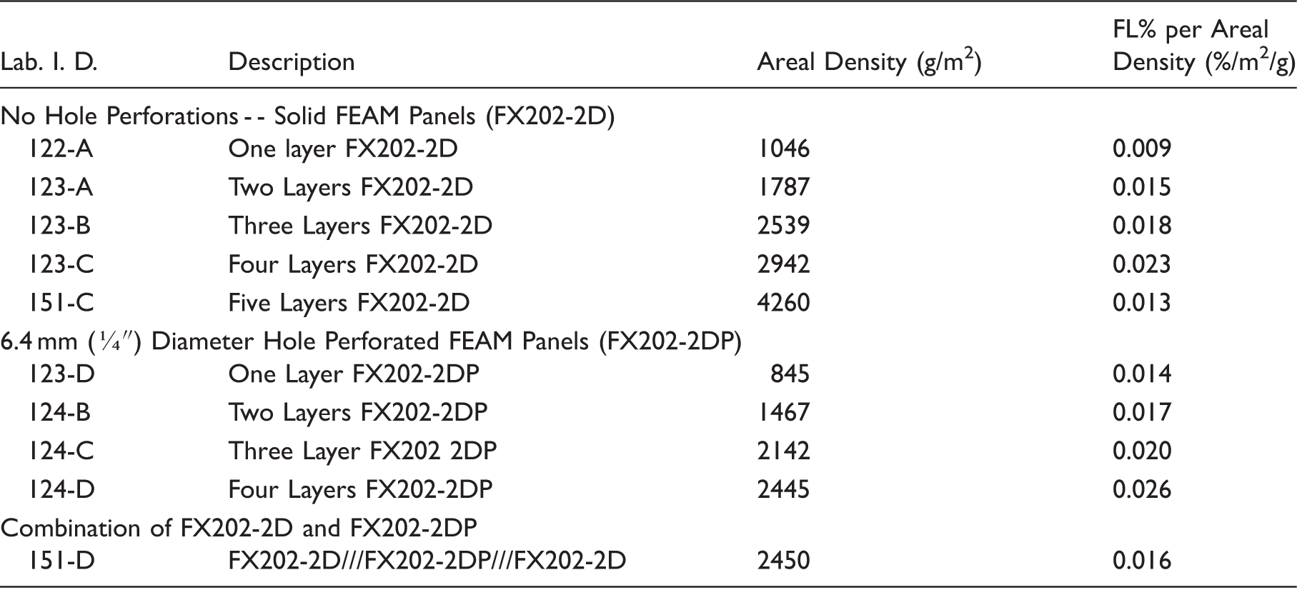
All multi-FEAM panels contained divider fabric between adjacent flocked surfaces
Non-barbed needle punching
Non-barbed needle punching of FEAM elements will be necessary if full 3D panel breathability is desired. It can be surmised from Figure 1 that all FEAM elements are inherently breathable in the ‘x–y’ (2D) direction because in flock fiber coated surfaces, the upright fibers are never so tightly packed that they block side-way breathability. Now, because flock adhesives are used to attach the flock fibers to the base or support fabric, the support fabric is rendered impermeable to air in the ‘z’ direction. However, breathability can easily be incorporated in the ‘z’ direction by needle punching holes through the FEAM element. By doing this, needle-punched FEAM panels are now rendered 3D breathable. In this study, needle punching of the FEAM layers was done manually using a sewing machine (Viking-Husqvarna, Emerald® 118) with a 1.0 mm diameter needle. The panel’s needle-holes were randomly located at an apart distance of about 4.9 +/–1.5 mm. In Table 4, comparing samples 126-A through 126-D (not needle punched) with samples 122-A, 123-A through 123-C (needle punched) the data show that the physical process of needle punching FEAM panels does not adversely affect to greatly the panel’s overall FL% properties. It was observed however that, non-barbed needle punching seemed to render these assembled FEAM panels a little more flexible.
Bending flexibility of FEAM panels
Bending flexibility of FEAM panel FX202-2D and needle-punched strips a

All deflection numbers are an average of at least two determinations
The needle-punched holes in these FX202-2D panels are random pattern holes about 3 to 7 mm apart and about 0.7 mm in diameter.
This sample is FX202-2DP (holes in FX202-2D panel are 6.4 mm (¼”) diameter and a 12.7 mm (½”) staggered distance apart).
Slits are in direction of cantilevered beam
Slits positioned across cantilever direction – reported cantilever deflections are the deviations from the ‘Bare Weight’ position.
Table 7 describes some of the unique modifications that were made to these FX202-2D and FX202-2DP panels. The deflection data were taken as the difference in the end position from its ‘bare’ own weight equilibrium position and the new end-position because of the added end-weighted. Table 7 first shows that the 2.5 g end-weighted panel strip that is needle punched can impart a measurable increase in bending flexibility to the material panel compared to the non-needlepunched material. Furthermore, the FX202-2DP sample exhibited a higher flexibility than the needlepunched panel. This should be expected since the bending cross-section of a hole perforated flat beam would involve the support of less cross-sectional material. It must be pointed out here that non-barbed needle punching does not involve any material removal. By combining hole-perforations with a needle, punching shows a marginal increase in flexibility. Overall, simple methods of increasing a FEAM panel’s flexibility have been demonstrated by these experiments. Because of the added advantage of 3D breathability and slightly higher sheet flexibility, no barb, plain needle punching of all FEAM sheet structures is recommended when considering FEAM materials for actual IEA pad applications. Needle punching of FEAM elements will be carried out for all subsequently prepared and tested FEAM experimental panels. In another experiment, to illustrate feasibility, the flexibility of FEAM panels was also evaluated relative to determine the effect of putting slits in the FEAM cantilever beam specimen. Unreported studies by the authors have shown that cutting slits in FEAM elements does not adversely affect their FL% properties. However, as shown in Table 7, slits parallel to the bending direction cause only a slight shift in a FEAM panel’s flexibility, whereas slits perpendicular to the bending direction have a drastic effect; FEAM flexibility is dramatically increased. This information should be valuable when designing complex shaped FEAM energy absorbing sporting apparel; slits may be a way of inducing ‘directional flexibility’ in a designed IEA pad structure.
FL% mechanisms for multi-layer FEAM assemblies
It is of interest to analyze the results of this experimental study regarding the energy absorbing mechanisms that are operating during the compressive deformation of FEAM and FEAM multi-layered panels. The structure of a typical single (double-sided) flocked FEAM panel was shown in Figure 1. Note that the wrapping fabric (PET micro-suede) for the tested module is not shown in Figure 1. The wrapping fabric is an important part of a FEAM pad structure since in practice it masks the abrasive feel-to-touch of the stiff nominally upright flock fibers that characterize the surface of FEAM elements. In addition to this ‘comfort’ effect, this wrap fabric also serves as a membrane to help distribute the stress imposed on a FEAM panel upon direct compressive deformation. If the impacting projectile is rounded or of a narrow blunt shape, the wrap fabric functions to distribute the striking force over a larger area of contact; a greater number of end-wise flock fibers will be involved in absorbing the impact force. This impact-strain deformation increase is also prominent in multi-layer FEAM configurations where divider fabrics are placed between facing flocked surfaces. The internal structure of a multi-layer FEAM panel is diagrammed in Figure 5.
Schematic diagram of three-layer FEAM panel configuration.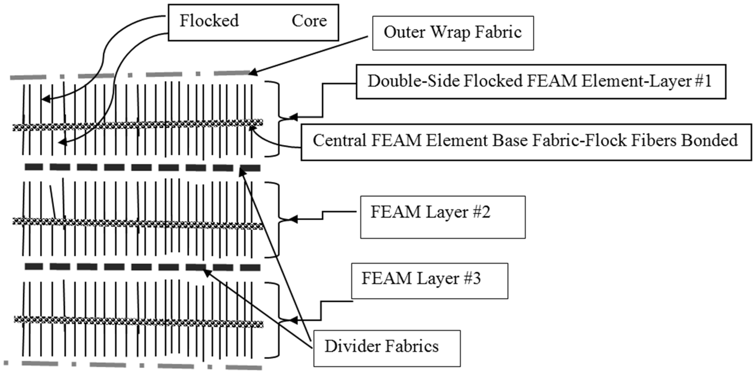
Energy absorption mode-sites in a three layer FEAM panel
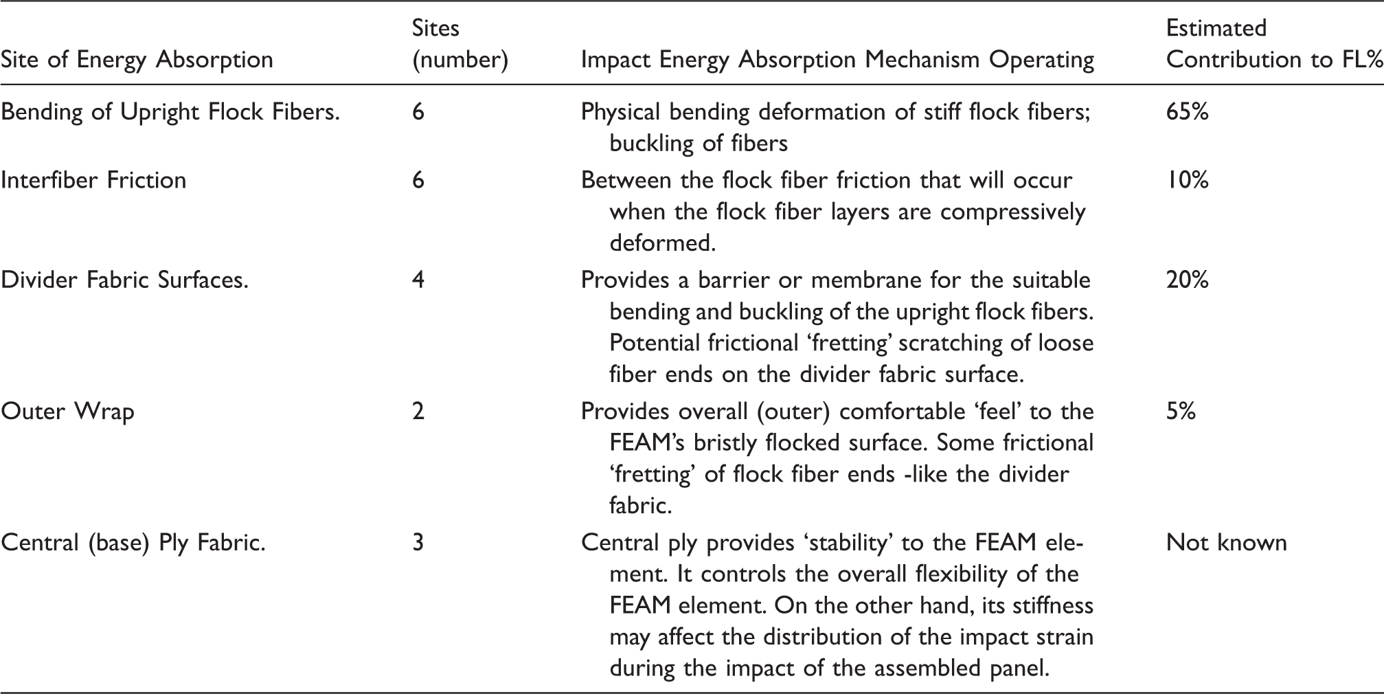
The proposed IEA mechanisms outlined in Table 8 can now be presented in terms of a linear equation, shown by equation (3)


Comparing FL% properties of FEAM with conventional IEA materials
In another series of experiments, BDT measurements were carried out on individual FEAM, foam, felt and spacer fabric materials. FL% results obtained for the foam, spacer fabric and felt materials are summarized in Tables 9 and 10. Comparing these FL% data with the FEAM data in Tables 4 and 5 we find that the FL% properties of the foam materials are much higher than the majority of the FEAM (alone and layered) panels tested. The only FEAM panels having comparable FL% properties are the four (stacked with divider fabric) layered FEAM configurations. The results show that the vinyl nitrile (VN 600) foam has excellent FL% properties, followed by the Poron® 15374-65 (polyurethane memory foam). Of interest too is the polyethylene (PE) foam which has a reasonably good FL% at a very low areal density. Felt layer materials that were impact tested exhibited FL% properties comparable to some of the FEAM panels but had generally lower FL% values. The FL% properties of the layered polyester fiber based felt materials were comparable to similar thickness of spacer fabrics. Finally, our tests showed that the FL% effectiveness of WKSF were moderate to low. Detailed discussions of the FL% performance of these impact absorbing materials follows.
Ball drop test results for various foam materials

The VN foam refers to vinyl nitrile foam materials obtained from Der-Tex Corp, Saco, ME; the samples with a P designation are perforated with ¼” diameter holes, 5/8” apart (see Table 2).
Poron® XRD foam from Rogers Corp., Rogers, CT.
PE refers to Polyethylene Foam obtained from Medco Supply Corp., Tonawanda, NY.
The FL% values for the PE foam were all lower than comparably thick vinyl nitrile or polyurethane foam. However, these results should be taken in the context of the very low areal density of PE foam (see Table 2). On a FL% per areal density basis, a brief calculation can show that the PE foam has the highest FL% to weight ratio compared to the other foams; a property worthy of note.

All test samples were wrapped in polyester micro-suede fabric and perimeter sewn
See Table 1 for material descriptions
WKSF refers to Warp Knitted Spacer Fabrics
DEFLEXION®, trademarked product of Dow Corning Corp. EA Spacer Fabric. (This material is no longer on the market by Dow Corning Corp)
FL% properties of FEAM panels combined with traditional energy absorbing materials
An important design approach for constructing energy absorbing pads using FEAM materials is to combine FEAM elements with traditional IEA materials. The goal of such an exercise is to create light-weight (low areal density) high IEA performing material helmet and body pad structures.

All test samples were wrapped in polyester micro-suede fabric and perimeter sewn.
See Table 1 for all material descriptions.
// denotes divider fabric used, / denotes no divider fabric
Numbers in parenthesis are the thicknesses (in mm) of the foam layers used.
Divider fabrics are used in FX202-2DP/VN-600P combinations to maximize the FEAM flock fiber bending. Flock fibers do not bend if they are compressed against a hole in the foam.
It is relevant here to note the good FL% performance of the light-weight FEAM/PE foam combinations. Overall, FEAM combinations with PE foam showed the least enhancement in FL%. However, these FEAM/PE foam combinations had the lowest areal density among the combinations tested. FEAM/PE foam combinations showed a very favorable FL% performance compared to the ‘bare’ PE foam. These results suggest that continued study of FEAM/PE foam combinations is warranted.

All test samples were wrapped in polyester micro-suede fabric and sewn perimeter.
See Table 1 for material descriptions.
// denotes divider fabric used, / denotes no divider fabric.
DEF an abbreviation for DEFLEXION®, Dow Corning Silicone Resin impregnated WKSF.
Examining Table 12 shows that FEAM panels assembled in combination with spacer fabrics have FL% properties that are slightly lower than the FL% properties of FEAM/foam combinations (Table 11). This might be expected since the spacer fabrics by themselves (Table 10) all had inherently much lower FL% performances. Table 12, also shows that the FL% properties of the combined WKSF’s and the FX202-2D and FX202-2DP are all quite similar. This is of particular interest because of the lower areal density of the combined panels employing the FX202-2DP (hole perforated) type FEAM. Overall, FEAM/spacer fabric combination showed remarkable improvement in FL% properties compared to the ‘stand-alone’ spacer fabrics. It appears that here too a synergistic effect might be operating. This is especially apparent with the WKSF-C containing FEAM panel. Notably, Table 10, shows that the FL% for the three spacer fabrics by themselves, in order of decreasing FL% effectiveness: WKSF-A>WKSF-B > WKSF-C. Now comparing the FL% properties these three WKSFs when assembled with FEAM outer layers, the combination panel containing the WKSF-C spacer fabric shows the highest FL%. Although this may be caused in part by the slightly thicker FEAM/WKSF-C/FEAM panel, it is believed that this observed FL% improvement (over about 40% better) effect is beyond what one would expect from this increased thickness. Under mechanical impact, the unique fibrous structure of the FEAM element coupled with spacer fabric (WKSF-C) layers results in a higher than expected FL% effectiveness. Why the FEAM/WKSF-B and FEAM/WKSF-A combinations did not perform better than the FEAM/WKSF-C panel is not known at this time. Could the reason be that WKSF-C has the lowest bulk density, is a little thicker and is the more easily compressed and softest (by a subjective finger ‘squeeze’ test) of the three WKSFs? Apparently, the role these WKSF ‘cores’ have in these FEAM/spacer fabric combinations is not straight forward. A critical question now remains; what is the fundamental FEAM/WKSF structural coupling (impact deformation profile) mechanism that leads to the observed improved FL% effects of these FEAM/WKSF spacer fabric combinations? This should be a topic of further study.
Possible synergistic effects in force loss (%) observed when combining FEAM with ‘bare’ foam, felt and spacer fabric materials

These ratio numbers are obtained by dividing the Force Loss (%) values of representative (3-layer) FEAM/foam/FEAM or FEAM/spacer fabric/FEAM configurations by the ball drop force loss (%) values obtained from ‘bare’ foam or spacer fabric material samples. The thickness differences between the combination panels and ‘bare’ IEA material layers are not taken into consideration in this simple analysis. Therefore, these ratio values should be considered as a very rough approximation of how much higher the FL% performance of the (3-layer) combination panels are over the FL% material (foam or spacer fabric) by itself.
Felt materials appear to have low dynamic impact compatibility with FEAM layers.
This qualitative ‘synergy index’ ratio is meant to approximate how much better the FL% performance of the combination samples are compared to the FL% of ‘stand-alone’ foam, spacer fabric or felt materials. Again, keep in mind that this ratio index value was determined without regard to the differences in thickness between the always thicker combination samples and the ‘bare’ foam, spacer fabric or felt panel materials.
This simplified data analysis suggests that the FEAM/WKSF/FEAM combination samples showed the strongest (apparent) ‘synergistic’ effect. The FEAM/felt combinations showed the poorest. Regardless, this classically simple analysis indicates that the use of FEAM in combination with foam and spacer fabric layers should be a desirable combination when designing IEA materials for apparel impact pad applications. These combinations should get serious consideration when creating an optimized IEA material for sport apparel pads. The data in Table 12 serve as a guide any future work.
Added to the feature of improved FL% performance be reminded that adding FEAM elements in any IEA structure will always render them 2D breathable and if the FEAM elements are needle punched or are hole perforated the resulting panels can be designed to be fully 3D breathable. Breathability and comfort are always a property to consider when creating an overall wearable product IEA pad design.
Impact blunting properties of FEAM/foam combinations
Given the enhanced FL% performance of FEAM/foam/FEAM combinations, the load-deflection behavior of this combination was further studied. As background, in laboratory measurements of the low strain rate behavior of foam materials, it was observed a ubiquitous ‘hump’ was observed in the material’s load-deformation curve at initial (low) strain levels. This ‘hump’ is characterized by an immediate increase in the foam’s resistance to compression followed by a leveling off at the 10% to 15% strain level range. Figure 6(a) illustrates this ‘hump effect’ for a series of vinyl nitrile foams of different volume density (hardness). These foams have been compressed to 40% strain and at 5 and 50 mm/min strain rate. The initial rapid low-level increase in stress is noted and is referred to as the so-called ‘hump’ in the load-deflection behavior. This initial characteristic ‘hump’ behavior could be problematic when using these foams for (impact absorbing) helmet padding. Recall that high-density foam materials are very commonly used as the IEA material of choice in sports helmets. From this observed characteristic effect, the question to ask is: Could a foam’s ‘hump effect’ possibly aggravate or enhance any head injuries occurring during the helmet wearer’s sports contact? Might it be possible that by eliminating this ‘hump effect’, one could lower by some degree, the severity of impact induced head injuries? These are questions worthy of consideration. To this end, additional low strain rate compression studies have been carried out on FEAM, foam and FEAM/ foam/FEAM layered combinations. These low strain rate compression tests were carried out using a procedure based on the ASTM D575 standard. Although low strain rate compression deformation tests at 5 and 50 mm/min for visco-elastic materials are not directly translatable to data obtained at impact ‘strike’ velocities (3 to 6 × 105 mm/min), some general similarities in compression-deformation behavior are possible. In the literature, comparisons between the low strain rate (‘static’) deformation level and impact velocity rate deformation for polyurethane foam have been reported with satisfactory results.15,16 One would expect that similar acceptable correlations exist in the low-strain-rate studies reported here.
Low strain rate (5 and 50 mm/min) compression deflection curves for (a) vinyl nitrile (13.1 mm thick) foam, (b) three and four layers FEAM (FX202-2D) assembled panels and (c) FX202-2D /foam/FX202-2D combination panels.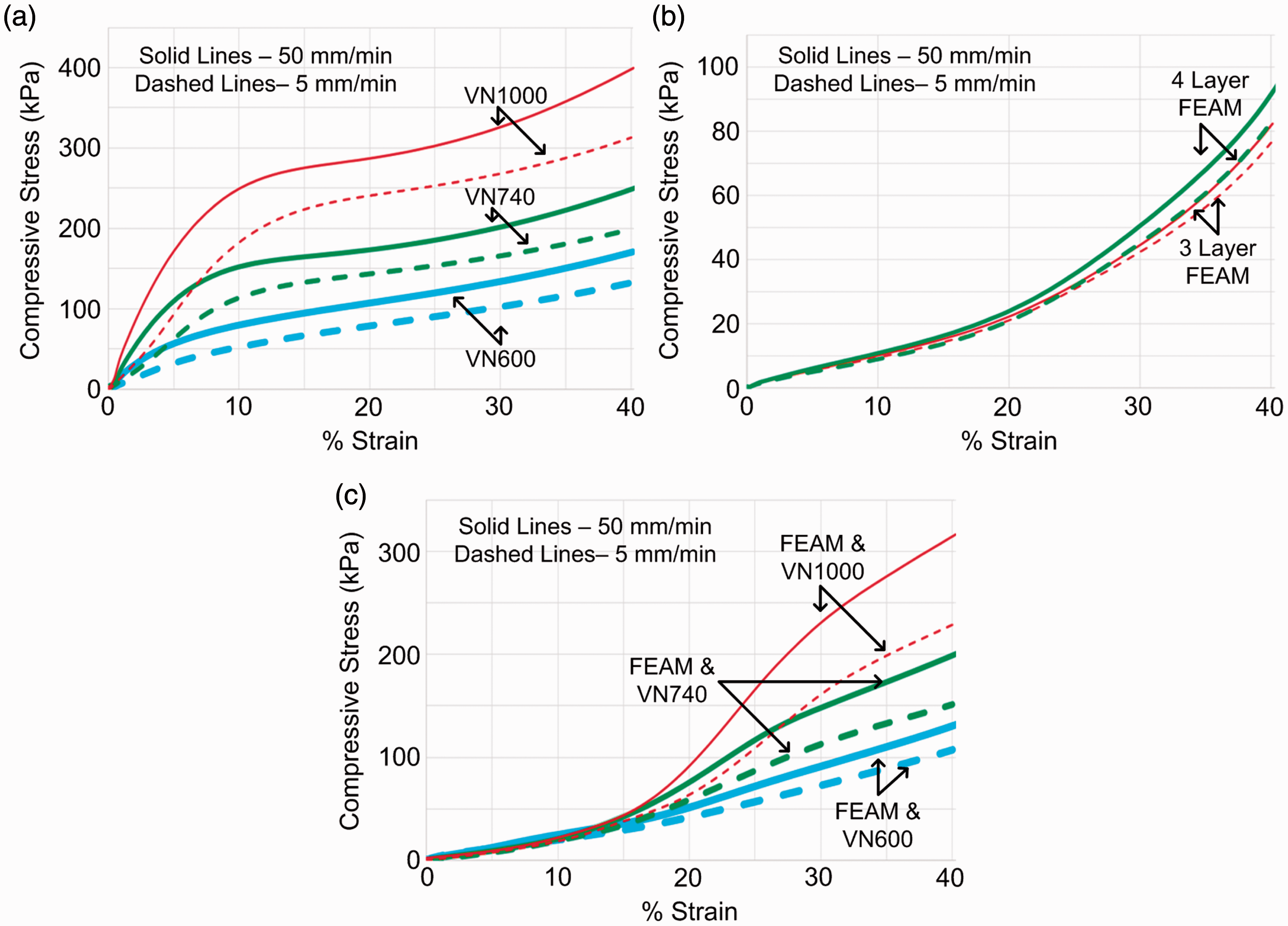
The Figure 6(a) data were obtained on 13.1 mm thick vinyl nitrile foam layers of three different areal densities/hardness (Shore 00): VN600 = 1466 g/m2/55-75, VN740 = 1644 g/m2/60-80 and VN1000 = 2192 g/m2/65-85. Figure 6(a) shows that the higher areal density and hardness of the impacted foam, the more pronounced in the observed ‘hump effect.’ Also, the data show that the foam’s ‘hump effect’ seems to be more pronounced at higher (50 mm/min.) strain rate. This suggests that this ‘hump effect’ could be strain-rate sensitive. It might be enhanced at higher (impact velocity) deformation rates.
Now for comparison, the low strain rate compression load-deflection behavior of three and four layered FEAM (FX202-2D) (with divider fabric) was measured with the data presented in Figure 6(b). As shown, a very gradual increase in stress occurs starting from the initial application of stress. The stress then very gradually increases as the level of compressive strain increases. Overall, Figure 6(b) displays typical load-deflection curves for FEAM elements in compression. Significantly, no ‘hump effect’ is observed. Also, both the three and four FX202-3D FEAM layer panels show almost identical load deflection curve behavior with the four-layered FEAM panel showing only a slightly higher compression stiffness. The difference in stress–strain behavior between the 50 mm/min and the 5 mm/min strain rate for these panels is very small if at all different. This suggests that the deformation of FEAM panel materials are less rate dependent than what was observed for vinyl nitrile foam.
Expanding on these findings, low strain rate compression tests were next carried out on various FX202-2D/vinyl nitrile foam/FX202-2D combination panels. Results of these measurements are summarized in Figure 6(c). It is first noted that the initial low strain level ‘hump effect’ completely disappears in these combination panels; this ‘hump effect’ has been ‘blunted’. Comparing Figure 6(a) with 6(c), the low and gradual increase in stress at low strain levels for the FEAM containing foam (central core) panels is seen. This smooth, gradual increase in stress is indicative of a less dramatic impact energy absorption rate process. These data for the FEAM/Foam/FEAM combination panel demonstrate the FEAM layer’s ability to effectively ‘blunt’ (lower the sharpness of) incoming impact strikes. Overall, FEAM’s ‘hump blunting’ properties should be of interest in the development of effective padding (e.g. sport helmet pad) materials. Finally, while these ‘hump effect blunting’ data were obtained at low deformation rates, similar data should be obtained at (much higher) impact velocity strain rates.
Finite element analysis (FEA)
A finite element analysis (FEA) modeling study was carried out to aid in discussing the results.5,6,12,13 A 2D axisymmetric transient dynamic FEA model consisting of a rigid projectile specimen and rigid base was created in ANSYS Workbench R14.5. This setup is shown in Figure 7(a).
(a) Impact FEA model on ANSYS Workbench; (b) element meshing, maximum compression and rebound.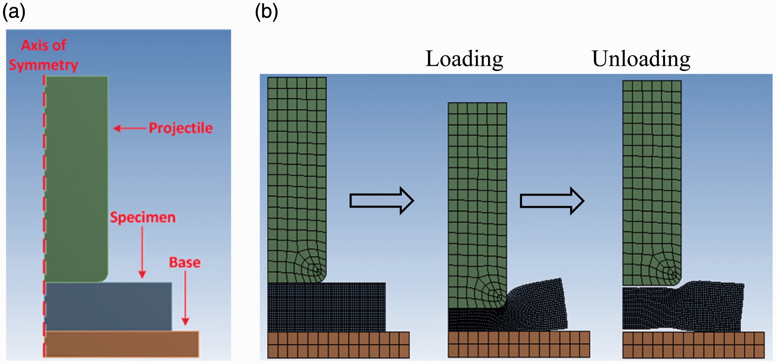
The stress–strain data used for the FEA was obtained during a drop weight experiment; where a 2 kg, 6.1 cm cylindrical, stainless steel projectile hit the specimen from a 0.5 m drop at 3.1 m/s. In this model, the stress–strain data were obtained for the specimen as a whole, completely assembled structure. This model is a macro-representation of the overall FEAM combination panel collapse event and is used namely for qualitative presentation. The drop weight that was used to obtain the stress–strain data was modeled in the FEA with the assumption that the flat surface of the projectile compressed the specimen uniformly. For simplicity, the curved nature of the projectile present in the ball drop experiments was not used in the FEA simulations because it would require multiple stress–stress data at various strain rates. This would have greatly complicated the FEA methodology. Instead, the selected ‘model’ specimen in this FEA simulation was a combination panel consisting of FEAM FX202-2D and vinyl nitrile foam. The make-up of this panel was: (1) VelTex® loop fabric (serves as a Velcro® hook adaptable outer wrap fabric); (2) one layer of FEAM FX202-2DP; (3) one layer of Vinyl Nitrile foam (VN-600P, 7.5 mm thickness); (4) a second layer of FEAM FX202-2DP; and (5) a Gehring-Tricot spacer fabric (GT873) (serves as a smooth outer fabric wrap layer. This combination panel had a global areal density about 2494 g/m2, and was chosen due to its unique performance in the FL% analysis from earlier sections.
To validate the FEA model, the measured velocity profile can be compared to the velocity profile from the simulation, which results in a coefficient of determination of 0.93. The results of this FEA simulation has enabled one to overview the strain and kinetic energies that occur during the compressive deformation of a combination material specimen; this overview is presented by the numerical results in Figure 8. Here it shows that there are three essential phases of the strain energy during the imposed compression loading events shown in Figure 7(b). These are similar to the phases described in Mills
1
for ‘stand-alone’ IEA material panels. In the Energy absorption results for a hybrid FEAM-foamfabric material.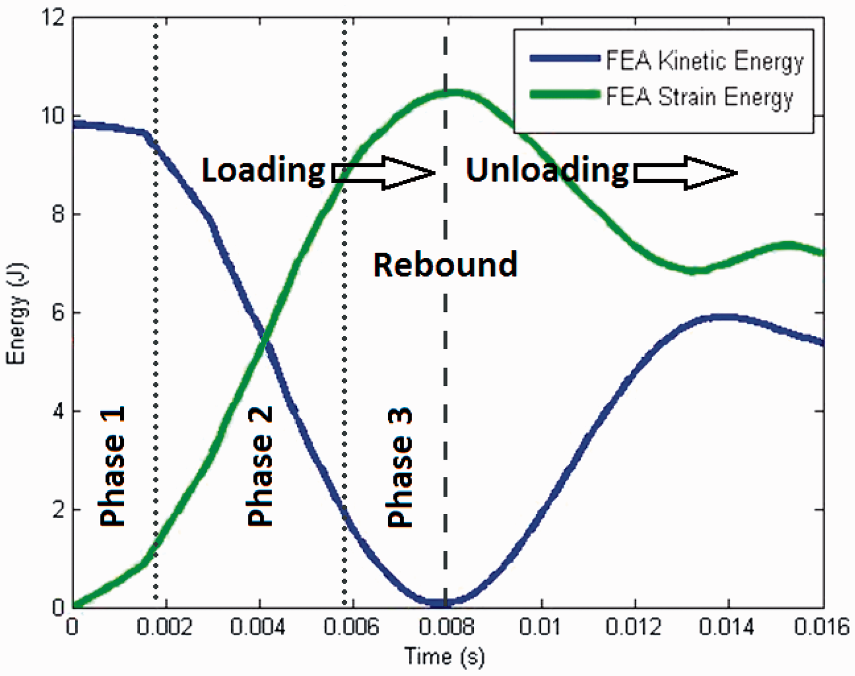
Summary of results
This paper presents an experimental review of the fundamental energy absorption properties of a (double-side flocked) FEAM configuration, FX202-2D, and its hole perforated version (see Table 1). Ball drop test results and determined FL% properties for FX202-2D and FX202-2DP can be considered representative of a standard FEAM structure. However, in must be remembered that the FX202-2D configuration is just one of many possible FEAM material designs. Overall, FEAM’s energy absorption properties must be well characterized before they can be successfully used for IEA (sport and military) apparel applications. This was the major goal of this paper. For example, FL% results indicate that the most efficient IEA structures involve the use of FEAM layering together two or more FEAM elements. This, of course, does not rule out the utility of single FEAM element structures for particular padding applications where reduced thickness is required. However, it is noted that all FEAM single and multiple-layer configurations must be encased, enveloped or otherwise wrapped in a fabric layer to ensure that the proper IEA functioning of the encased flocked fibers. Additionally, when dealing with multi-layer FEAM panel assemblies, it is crucial that divider or separator fabrics be placed between the flocked surfaces of contiguous FEAM layers. The flock fibers of face-to-face flocked surface layers must be prevented from inter-meshing or interpenetrating each other. Divider fabric or film layers have been clearly shown to provide these FEAM structures with higher FL% properties. Divider fabrics allow for the needed (reversible) compression spring-action required to optimize a FEAM structure’s IEA properties. In this inaugural study, some important FEAM design criteria have been uncovered. From the standpoint of developing IEA helmet and apparel pads, the following conclusions can be made.
Presently available ‘bare’ stand-alone, single element, double-sided flocked FEAM layer structures have minimum effectiveness in absorbing impact energy. However, individual FEAM layers that are covered with or enveloped in fabric or membrane are more effective in FL% absorption than bare (open flock) FEAM surfaces. Cover fabrics/membranes serve to distribute the impact force over a greater number of flock fibers and fiber ends during compressional impact. Future research should be directed to improve the FL% properties of single (double-side flocked) layer FEAM configurations. Multi-layer FEAM structures can be designed to be efficient breathable impact force absorbing structures. However, FL% efficient FEAM layers can only be created when divider fabrics/membranes are placed between adjacent, multiple FEAM layer panels. Divider fabrics can be thin, lightweight plain weave or air permeable fabrics or thin, small hole perforated and or breathe-through polymer films. FEAM panels having holes punctured through their areal cross-section (e.g. 6.4 mm (1/4″) diameter, 12.7 mm (1/2″) apart staggered hole with divider fabric) have FL% properties that are slightly lower than non-hole, planar FEAM panels. However, hole containing FEAM panels are found to have the desirable property of a higher FL% per areal weight compared to the no-hole panels; this is an important design consideration if an IEA pad material having the highest IEA properties at the lightest weight is desired. Non-barbed needle punching of FEAM elements/layers should always be performed on FEAM materials when developing them for use in helmet and apparel padding applications. Needle punching punctures the central or base support ply of the FEAM element thereby making the FEAM assembly fully 3D breathable. Needle punching also renders the overall FEAM panel slightly more flexible. Possible mechanisms of energy absorption mechanism in multi-layered FEAM panels have been proposed. The major sites for IEA are believed to be (a) the visco-elastic (spring) bending/buckling action of the upright flock fibers, (b) the inter-fiber frictional (rubbing) effects of the deforming fibers and (c) frictional ‘fretting’ of the flock fiber ends against the divider and wrap fabric (membrane) surfaces. A better understanding of these IEA modes will be needed to optimize the IEA properties of FEAM materials. Although layered FEAM elements by themselves do not match the FL% performance of most foam materials, when FEAM layers are combined with foam or spacer fabric layers, the FL% of the resulting panels are greatly enhanced. In fact, a possible ‘synergistic effect’ was found in these material combination studies. This ‘synergistic effect’ was most pronounced when FEAM was combined with certain spacer fabric structures. The initial rapid rise in stress (the so-called ‘hump effect’) that occurs under the low strain rate compressive deformation of vinyl nitrile foam is found to be greatly reduced if not eliminated by sandwiching the foam between FEAM layers. It is believed that this ‘hump effect’ can be problematic when using vinyl nitrile foam in sport helmet pads. Eliminating this ‘hump effect’ could lessen the ‘sharpness’ of an impact ‘hit’ allowing for a more gradual force impulse event to the head of the helmet wearer. This more gradual impact force control mechanism may very well lead to lessening the severity of sport-related head injuries.
Concluding remarks
This paper deals with the impact force loss behavior of flocked surfaces being struck by a high-speed spherical projectile normal to the perpendicular direction (ends) of short/stiff fibers. Although flocking is a well-established technology, until this publication, these unique textile structures have not yet been explored for IEA applications. Therefore, new knowledge has been added to the field that should lead to new exploratory research on the use of flocked fabrics for sport, military and civil-servant IEA apparel and pad applications. However, what was not clearly pointed out was the added comfort issue attributable to the use of FEAM layers in IEA strictures and the combination of FEAM layers with other more traditional IEA pad materials. For example, when FEAM layers are placed on both sides of a foam core, the assembly is inherently rendered 2D breathable. This FEAM induced breathability and wearer comfort property should provide an added benefit when choosing to use FEAM layers to any sport, military or civil servant protective apparel or helmet pad assembly.
All our herein reported data indicate that the ‘center’ of IEA action in these FEAM elements is the flock fiber springing, bending and buckling mode action that is operating during compressional deformation. Importantly, this reported study used only one of many possible FEAM configurations (2 mm long, 20 denier nylon, double-side flocked onto a thin nonwoven fabric) that are possible. It is proposed that a parametric study be carried out on finding the optimum flock fiber type (PET or Nylon), fiber length, fiber denier, fiber cross-sectional shape and flock density that will result in maximizing FL%. The effect of the ‘base’ or support ply fabric on FL% properties should also be investigated. The feature that FEAM elements can be double-side flocked or single-side flocked should also be investigated. The observation that a possible synergistic effect occurs when FEAM layers are combined with foam or spacer fabric is an important result. There must be a special mechanical coupling event occurring when these layered structure are impacted. This effect should be studied further. All these research ideas should be pursued with the goal of obtaining more information on how layered flocked surfaces can be applied to new designs of IEA material products. To this end, results presented suggest that one should be able to create, design and engineer some very light weight, thin cross-section, high impact energy absorbing assembled panel and pad materials.
Flocked surface layer energy absorbing materials provide a new textile materials approach to manage or mitigate head injury causing impacts during the rigors of playing the various contact sports. (football, ice hockey etc.). Over the decades, football helmets have undergone incremental improvements as new and innovative materials came on the scene and were adopted to reduce impact force causing concussive injuries. Innovations like FEAM may provide an increased capacity to lower the dynamic stress characteristics associated with the accidental offset of concussive injuries.18,19 In the future, FEAM material will be impact tested using a range of masses, compliance, impact velocities and locations to reflect realistic conditions experienced during sport action play. For football and ice hockey applications, it is most important that the shear/rotational/torsional IEA properties of FEAM structures be studied. Impact testing modes should reflect more realistic conditions. A combination of drop tests that reflect falls as well as helmet-to-helmet linear impacts should be investigated. The resulting dynamic response of the head during such impacts should be documented using both linear and rotational acceleration time curves. These performance tests will provide the necessary analyses to establish the ability of FEAM materials to decrease the risk of concussive injuries in football, military and societal functional action settings.
Footnotes
Declaration of conflicting interests
The author(s) declared no potential conflicts of interest with respect to the research, authorship and/or publication of this article.
Funding
The authors received no financial support for the research, authorship and/or publication of this article.