
Abstract
In textile factories, the sliver can is used to deposit and transport sliver in the process of carding, combing and drawing. Increasing the capacity of the sliver can will reduce the frequency of changing the sliver can; hence, the working efficiency can be improved. A belt drive mechanism with the driven pulley eccentrically installed was developed in this study. This mechanism was used as the driving mechanism of the coiler, which has the effect of increasing the capacity of the sliver can. In this study, several commonly used methods of increasing the capacity of the sliver can were introduced first. Then, the equation of motion of the eccentric belt drive mechanism was established, and the law of motion of the driven eccentric pulley was calculated. Finally, the relationship between the eccentricity (e) of the driven eccentric pulley and the capacity increment (δ) of a sliver can was analyzed by utilizing the evaluation indicators of density of per sliver lap. The result indicates that with the increase in the value of eccentricity (e), the capacity increment (δ) of a sliver can also increases.
Keywords
In textile factories, the sliver can is used to deposit and transport sliver in the process of carding, combing and drawing. Increasing the capacity of the sliver can will reduce the frequency of changing the sliver can; hence, the working efficiency can be improved. It is therefore necessary to study how to increase the sliver can’s capacity.1–8 Many methods of increasing the capacity of the sliver can have been investigated. Chen et al.9–11 established the relationship between the center hole diameter of the sliver with the diameter of the sliver can and the width of sliver, and then derived the value of the center hole diameter when the volume of the sliver is greatest. Zhou 12 discussed the sliver overlapping in the densest zone around the hole of the can coil package, and derived the equations of the maximum coil package to determine the optimal eccentricity between the coiler and sliver can center. However, the above two methods cannot increase the capacity of the sliver can. Huang 13 proposed a hold-down mechanism that can press the sliver tight and increase the number of sliver layers in the same can height, leading to the increase in the capacity of the sliver can. However, this kind of hold-down mechanism is complex and not easy to maintain. When the pressure head compresses the sliver column, the sliver will be damaged by the pressure head and thus decrease the quality of sliver. Gao et al.14–16 proposed an reciprocating turntable coiler (RTC) coiling system, a device for increasing the capacity of the sliver can. The principle of the RTC coiling system is that the sliver can rotates around its axis and at the same time reciprocates slightly. This improves the sliver storage density along the radial direction of the sliver can, which consequently increases the capacity of the sliver can. However, in order to meet the sliver can’s motion, a driving mechanism that makes the sliver can reciprocate must be added. This not only increases the production cost, but also reduces the reliability of the machine. The Rieter Company17,18 designed a new coiling system and compared it with the common coiling system; the features of this new device are that the sliver can is rectangular and the motion of the sliver can is the combination of reciprocating linear and clearance swing. This device can also increase the capacity of the sliver can. The new coiling system is simple and compact, although it does not have the capability to prevent impurity accumulation in the inclined tube.
Different from above studies, a new kind of coiler driving method is proposed in this study. It is based on an eccentric belt drive mechanism rather than any complicated mechanism. This new mechanism has the advantages of low cost, simple structure and convenient maintenance. This application not only can increase the capacity of the sliver can, but also has the capability of preventing impurity accumulation of the inclined tube.
The kinematic analysis of the eccentric belt drive mechanism
Firstly, we denote that point O is the rotational center of the driven pulley, and point O2 is the geometric center of the driven pulley. The distance between point O and point O2 is e (i.e. OO2 = e). Point O1 is defined as the rotational and geometric center of the driving pulley. At the initial position of this mechanism, points O, O1 and O2 are on the same line, and point O2 is on the left-hand side of point O, as shown in Figure 1.
Geometric center of the driven pulley O2 locates above the x-axis.
The geometric center O2 of the driven pulley is above the x-axis
Suppose φ is the angle between line OO2 and the negative direction of the x-axis. Clockwise is defined as the positive direction. The tangent point between the belt and the driving pulley is denoted as point A. The tangent point between the belt and the driven pulley is point B. Line AC is parallel to line O1O2 and intersects with line O2B at point C, as shown in Figure 1.
In this study, the elastic sliding of the belt drive mechanism was ignored. The radius of the driving pulley and the driven pulley were denoted as r1 and r2, respectively. We also denoted the distance of line OO1 as a, the distance of line O1O2 as b, the distance of line OB as r, the linear velocity of the driving pulley and the driven pulley as V and V2, respectively, and the angular velocity of the driven pulley as
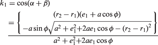
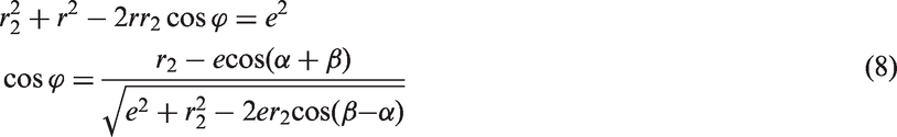
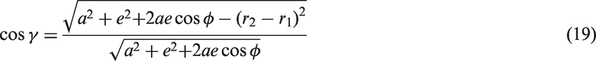
From ΔOO1O2 in Figure 1, the cosine law gives


In ΔABC

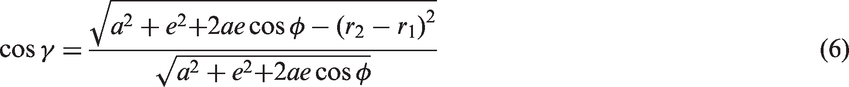
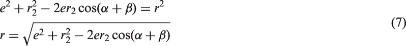
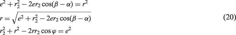
In ΔOO2B


The geometric center O2 of the driven pulley is below the x-axis
From ΔOO1O2 in Figure 2, the cosine law gives
Geometric center of the driven pulley O2 locates below the x-axis.


In ΔABC

In ΔOO2B

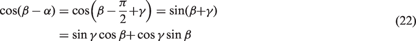
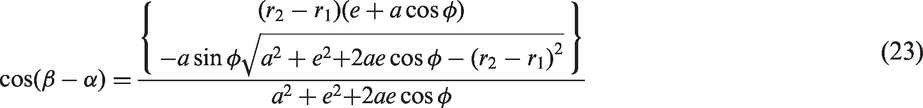


In summary, because

so


According to equation (27), given the value of the relevant parameters, the curve describing the relationship between Relationship between 
Application of the eccentric belt drive mechanism on the coiler
Chen and Liu 19 proved that the density of sliver along the diameter direction of the sliver can is not uniform, and the highest winding density is located in the circular ring near the center of the sliver can, which is called the region of the hard core. The utilization ratio of the sliver can mainly depends on the number of sliver layers near the center of the sliver can.
A belt drive mechanism with the driven pulley eccentrically installed was used as the drive for the coiler in the present study. It ensures that the coiler rotates quickly when the coiler outlet approaches the center of the sliver can, and rotates slowly as the coiler outlet approaches the sliver can wall. The following analysis proves that this kind of drive mechanism can increase the capacity of the sliver can, while the sliver density of the hard core zone decreases.
The density of per sliver lap at the diameter direction of the sliver can
The slivers form a cycloid shape in the sliver can because of the coordination motion of the coiler and the sliver can.20–24 However, the rotational speed of the sliver can of the coiler is very low compared with the rotational speed of the coiler. To simplify the calculation, we ignored the rotational speed of the sliver can and the cycloid shape was approximately taken as a circle.
As shown in Figure 4(a), we denoted the center of the sliver can as the center of a circle, the radius of the outlet of the inclined tube as r, the radius of a series of concentric circles as R, the inner and outside radius of the ring as R1 and R2, respectively, the width of the sliver as d and the eccentricity between the coiler and the can as e1.
Intersection of the circle of radius R and the sliver ring: (a) 
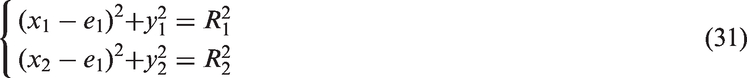
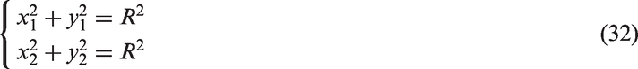
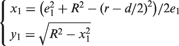
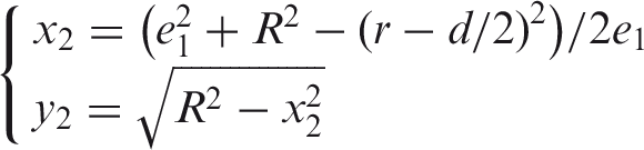
The two points at which a circle with radius of R intersects with the approximate circle are P1 (x1, y1) and P2 (x2, y2), respectively, and


A rectangular coordinate system was established, as shown in Figure 4(a). Regarding the geometric center Q of the sliver can as the origin of coordinates, the sliver’s inner side and outside trajectory equations are
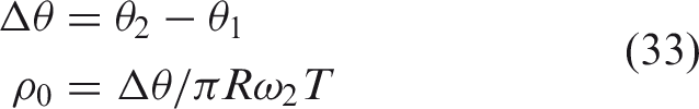
The intersection position between the circle with radius R and the sliver ring changes along with the change of R; therefore, three cases are listed bellow to calculate the DPSL When When When We can achieve the arbitrary values of Case 1
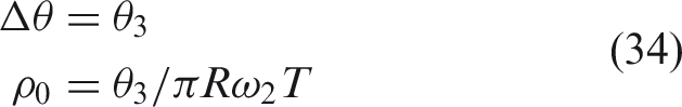
Case 2
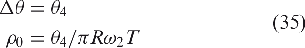
Case 3
DPSL with the two coiler drive mechanism
The coiler is driven by a concentric driven pulley
Take the RBS-D30 drawing frame produced by the Rieter Company as an example, where r = 110 mm, e = 60 mm, D = 350 mm, d = 10 mm, T = 2/9 s and Density per sliver lap (DPSL) with concentric installation of the driven pulley.
In Figure 5, point H represents the maximum point of the curve, which indicates the highest winding density located at this point. The radius of the corresponding point H is equal to the sum of the radius of the blowhole and the width of the sliver. However, after point H, with the increase of the sliver can’s radius, the value of DPSL drops sharply and reaches the minimum point L; the lowest winding density locates near point L. When R is approaching the wall of the sliver can, the value of DPSL gradually increases. We can establish, therefore, that the density of the sliver along the diameter direction of the sliver can is not uniform, which causes the problem of low utilization ratio of the sliver can. The result we achieved is consistent with Chen and Liu’s 19 conclusion.
The coiler is driven by an eccentric driven pulley
According to Figure 3(b), set the initial position of the coiler reasonably to ensure that when the sliver outlet of the coiler approaches the center of the sliver can, the rotational speed of the coiler is high, and when the sliver outlet of the coiler approaches the sliver can wall, the rotational speed of the coiler is slow.
26
In this way, the utilization ratio of the sliver can is improved. Similarly, the DPSL at the sliver’s diameter direction plotted with MATLAB® (Math Works Inc., USA) is as shown in Figure 6.
Density per sliver lap (DPSL) with eccentric installation of the driven pulley.
In Figure 6, because the coiler rotates with the fastest speed when the coiler outlet approaches the center of the sliver can, the sliver deposited at the center of the sliver can decreases, as does the value of DPSL of the hard core zone. Hence, the capacity of the sliver can will increase.
Discussion
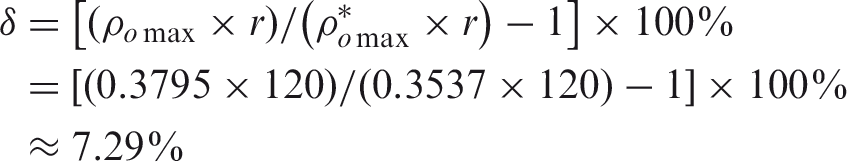
We combine the above two curves into one coordinate system, as shown in Figure 7. From Figure 7(b), we achieved the maximum DPSL decrease from 0.3795 (constant speed) to 0.3537 (variable speed). Because the DPSL of the hard core zone decreases, the sliver can could hold more layers of sliver. We established, from Figure 7(c), that the maximum DPSLs of the two cases are 0.2283 (variable speed) and 0.2202 (constant speed). The maximum DPSL with concentric installation of the driven pulley is larger than that with eccentric installation of the driven pulley; however, the utilization ratio of the sliver can mainly depends on the DPSL near the center of the sliver can. This means the capacity of the sliver can will increase. The capacity increment of the sliver can is
Comparing the DPSL of two cases: (a) overall comparison drawing; (b) local enlarged drawing of area B1; (c) local enlarged drawing of area B2.
The above results were calculated by taking the eccentricity (e) of the driven pulley as 6 mm (i.e. e = 6 mm). With the different values of eccentricity (e), the values of capacity increment (δ) are also different. Taking eccentricity (e) as 4, 5, 6, 7, 8, 9 and 10 mm, respectively, the capacity increments of the sliver can’s (δ) corresponding eccentricity (e) are 5.41%, 6.36%, 7.29%, 8.27%, 9.27%, 9.81% and 10.51%, respectively. According to the above calculated values of these points, the relationship between δ and e was plotted with MATLAB® (Math Works Inc., USA), as shown in Figure 8. Figure 8 shows that, with the increase of eccentricity (e), the capacity increment (δ) of the sliver can also increases. From Figure 8, we also found that the relationship between the eccentricity and the capacity increment is not linear.
The capacity increment of different eccentricities.
However, the value of eccentricity (e) should not be too large as it could aggravate the vibration of the coiler and worsen the machine’s work condition. In order to minimize the vibration of this mechanism at the working condition with a high speed, the optimal eccentricity (e) must be confirmed. To come up with the optimal eccentricity (e), some factors, such as accidental drafting of sliver, the capacity of the sliver can, the vibration of this mechanism and so on, need to be considered comprehensively. Therefore, much work needs to be done. In the next stage of our research, we will set up an experimental platform to carry out relevant experiments to confirm the optimal condition with mechanism running and optimal eccentricity (e), and to verify the results achieved in this study.
Conclusions
In this study, a new belt drive mechanism with the driven pulley eccentrically installed was proposed. It has the advantages of low cost, simple structure and convenient maintenance. The relationship between the angular velocity (
Driven by this mechanism, the coiler can also achieve a motion with periodically varying speed. Following the motion rule of the driven eccentric pulley, the initial position of the driven pulley should be appropriately adjusted to ensure that the coiler rotates quickly when the coiler outlet approaches the center of the sliver can, and rotates slowly as the coiler outlet approaches the sliver can wall. This mechanism can not only increase the capacity of the sliver can, but also has the capability of preventing impurity accumulation of the inclined tube.
Footnotes
Declaration of conflicting interests
The authors declared no potential conflicts of interest with respect to the research, authorship and/or publication of this article.
Funding
The authors disclosed receipt of the following financial support for the research, authorship, and/or publication of this article: This work was supported by the National Science and Technology Support Program of China (grant number 2011BAF08B03).