



Abstract
Twisting is an important process to form a continuous yarn from short fibers and to determine the structure and properties of the resultant yarn. This article reports on the effect of variation of false twist on process stability and resultant yarn quality in a modified ring spinning frame. Based on twist kinematics, three practical cases that cause twist variations in the spinning process are investigated, namely step function, rectangular function and periodic function changes in false twist. The simulation results are validated by experiments and a good agreement has been demonstrated. The resultant properties of yarn within 30% periodic change in false twist demonstrated insignificance compared with yarn without variation. With the developed model, essential system parameters are numerically examined and their quantitative relationships are studied. The practical implications are discussed.
Spinning is a fundamental method to impart strength and make continuous yarns by twisting short or staple fibers. 1 The yarns are then woven or knitted into fabrics for apparel and home-textile applications, where cotton, wool or man-made synthetic fibers are used. 2 With an output of 41,021,976 tons produced from all fibers and world cotton consumption of 23,633,845 tons in 2012, spun yarns show the dramatic swell of global textiles and apparel industry in the past decades. 3 In terms of the spinning technologies, ring spinning is the most dominant method since it can produce high-quality yarn and has a wide spinnability to majority fiber materials and yarn counts. 4
Based on the conventional ring spinning method, a modified technique has been proposed for producing a low-residue torque and soft handle singles yarn by introducing a friction-belt false-twister. 5 Due to the incorporating of the false-twister, twist distributions in the yarn spinning zone are altered. In the upstream of the false-twister, a high twist level is achieved by combined twist coming from the false-twister and twist propagation through the false-twister from the traveler, which modifies the geometry of spinning triangle and greatly influences the distribution of fiber tension forces and fiber arrangements in a yarn, resulting in modified yarn structure and properties; while in the downstream of the false-twister, a low twist yarn is obtained by adopting a low twist factor, which results in a low-residue torque and soft handle style. Structural analysis revealed that in the modified cotton ring yarns, most internal fibers have much lower inclination angles and some fiber segments have the inclination angle of alternating direction, thus yielding a reduced resultant contribution to the total yarn torque. In addition, the modified cotton yarns have a densely packed zone which is located somewhere half way from the center to the surface of the yarn; thus the yarn of low twist can still hold itself with a reasonable tenacity and exhibit good pilling performance. Comparative studies4,6-9 have demonstrated that the modified cotton yarns and fabrics have significant advantages in terms of soft handle, higher yarn strength at lower twist factor, lower residual torque and low knitted fabric spirality after washing and tumble-dry cycles.
Twisting is an important process to form a continuous yarn and to determine the structure and properties of the resultant yarn. 10 Uniform twists inserted into the yarn ensure even features and good yarn quality. Twist variation in the spinning process may results in poor spinnability as well as uneven features or imperfections of the resultant yarns, such as strength deterioration, diameter irregularity and wrapping fibers along yarn length. On the other hand, for a stable process or product, it should permit a certain tolerance for the system variation or error. In past decades, investigation of the twisting process has attracted interest from many researchers in the fields of ring spinning,11–14 rotor spinning,15,16 friction spinning,17,18 self-twist spinning,19–22 air-jet spinning,23,24 etc. In particular, Fraser et al. 25 studied the effect of yarn non-uniformity in the ring spinning process, and quantified that even a slub that in practice would be considered quite small can have a significant effect on the stability of the yarn balloon. Denton 26 investigated the effects of twisting-rate variations in the false twist-texturing process and demonstrated that an oscillating twisting rate can generate an amplitude of twist in the downstream zones greater than the original variation in the texturing zone. Thus, it is of great concern whether the system which combines the ring spinning and false-twisting methods is stable or not; however, little work on this novel topic could be found in the literature.
It is clearly important to develop a theoretical model to describe the effect of false twist variations on the yarn twist redistributions in the spinning process as well as evaluation of the yarn quality subject to external perturbations. Therefore, in this paper, equations are derived to evaluate the twist variations subject to external perturbations based on twist kinematics.26–28 The model is then verified by experimental observations, and yarn properties subject to the variation of false twist are examined. The main purpose of this study is to assess the stability and robustness of the modified technique, and to comprehend the effect of system parameters on dynamical twist redistributions.
The modified ring spinning system
As shown in Figure 1, a translationally moving belt was introduced into the conventional ring spinning frame and installed between the front rollers and yarn guide. In the modified spinning system, there are two twisters: one is the real-twister at point B; another is the false-twister which generates the torque by the frictional moment at point A. Correspondingly, the yarn path can be divided into three zones: zone OA between the front rollers and the false-twister (l1); zone AB between the false-twister and the traveler (l2); and zone BC between the traveler and the winding point (l3). The winding point is also called wind-on or lay point, where it is wound onto the bobbin carried on the spindle which is coaxial with the ring. During the spinning process, the yarn moves at a constant velocity v, but its twist level is altered in different zones.
A schematic diagram of a modified ring spinning system.
In order to describe the function played by the moving belt, three parameters are introduced. The first parameter is the false-twisting efficiency of the moving belt. At the contacting area of the yarn surface and the moving belt, the frictional moment forces the yarn to rotate along its axis. If there is no slippage or jumping of the yarn on the moving belt, then the yarn’s tangential velocity and the moving velocity of the belt at the contacting point should be the same. In this situation, the false-twisting efficiency of the moving belt is unity, but normally the false-twisting efficiency is a value close to but below the unity. The false-twisting efficiency of the moving belt is expressed as

The second effect is the twist trapping in the upward propagation of the real twist inserted by the traveler. Without the existence of the belt, the yarn twist generated by the traveler can be freely propagated into zone OA. Due to the introduction of the moving belt, a certain proportion of this twist is blocked because of the frictional moment generated at point A. To quantify this effect, the propagation coefficient of twist trapping is defined as

The last effect is the twist congestion, which occurs in the downward propagation of twist in zone OA. The downward-traveling yarn has a twist thus a tendency to untwist on the belt. It is subject to another frictional moment, as a result, the rotating trend of the yarn is reduced, which blocks the yarn twist propagating into zone AB. The result is that the yarn twist is increased in zone OA. The propagation coefficient of the twist congestion is defined as

Theoretical Modeling
Assumptions
The following assumptions are made to simplify the theoretical modeling:
Twist distribution in each zone is regarded as linear superposition of twists from the traveler and the false-twister; Yarn slippage rate on moving belt, coefficient of belt twist congestion and trapping are constant throughout; The effects of twist blockage caused by the yarn guide and the traveler are neglected; The effects of twist-contraction in each zone are neglected; The twist is evenly distributed in each zone; The yarn delivery speed is constant in each of the three zones.
Twist distributions in the steady-state
From the kinematic point of view, the twist in zone OA can be expressed as

In zone AB, the friction-belt inserts turns into the yarn at the same rate as in zone OA, but in the opposite sense, which offsets the positive twist passing from zone OA. Therefore, the twist in zone AB in the steady-state is

In zone BC, no turns will be generated in this section and the twist in zone BC remains the same as that in zone AB

Twist redistributions in the transient-state
In some occurrences, yarn twist in three zones are altered due to the temporary or transient change of false twist such as variation of the belt moving speed, variation of the wrap angle of the belt and the yarn, and variation of yarn diameter. For easy derivation and experimental implementation, the change of belt moving speed is adopted as an example. In terms of the mode of variations, three functions are commonly used, namely step function, rectangular function, and periodic function. In this study, the periodic variation of the false twist is of particular interest because it meets the most practical applications, while the other two modes are also derived in the Appendix. In the transient-state, twist redistributions vary with time due to the altered false twist by changing the belt moving speed, while the real twist remains unchanged. As mentioned above, the twist redistribution in each zone is the linear superposition of real twist and false twist. Therefore, the total twist in each zone is the sum of the unchanged real twist and altered false twist.
The impact on the development of twist redistribution by false twist variations during nominally steady-state running is of much great practical interest. Hence, equations are developed that describe the way in which twists in the three zones of a modified ring spinning machine alter by a sinusoidal change in belt twisting rate. In this example, the belt twisting rate is given by the expression
False twist in zone OA
The turns gained by the moving belt in a time increment dt are

False twist in zone AB
The turns passing through the belt from zone OA are

False twist in zone BC
The turns passing through the traveler from zone AB are

Therefore, yarn total twists in each zone can be expressed by

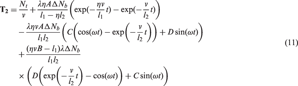
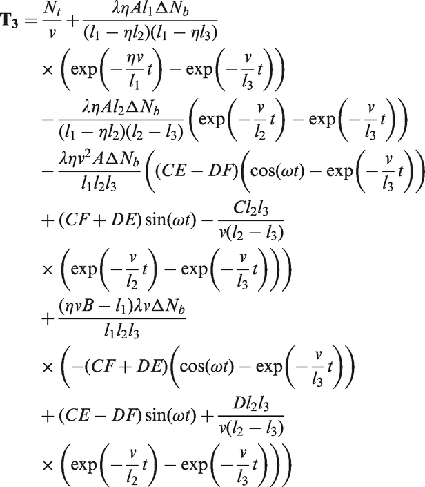
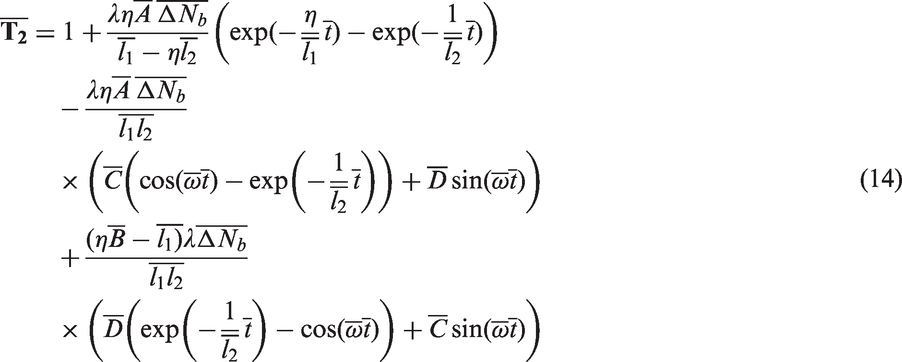
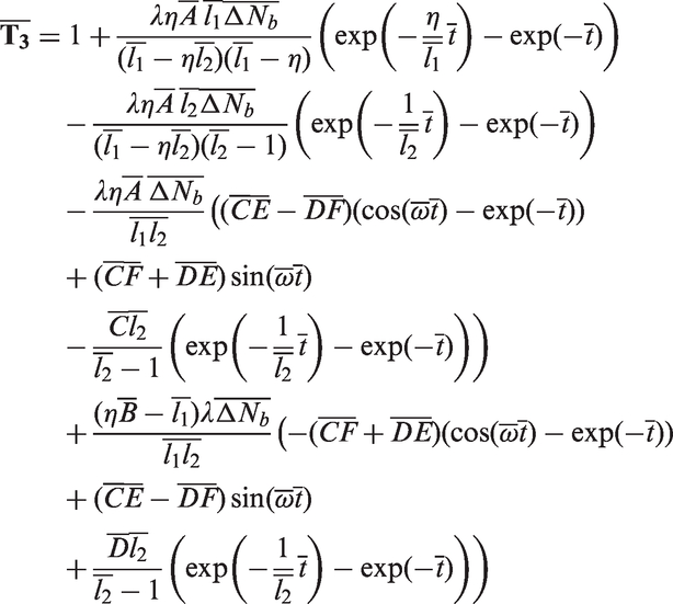
Transforming Equations (10–12) into the dimensionless form, one obtains


Experimental verification
Experimental setup
The experiments were conducted on a ring spinning frame (Zinser 351) by installing a Polyurethane belt with diameter of 3 mm between the front rollers and the yarn guide. The belt was driven by a 0.75 kw AC motor (NERI MOTORI) and the belt speed was controlled by a 220 V single-phase inverter (Shanghai JINQV Automation Ltd., Co.; Model:VFD-V-2S0007B). The online control of the instant belt moving speed was accomplished by the embedded PLC module. In order to monitor the instant belt speed, a Hall speed sensor (SHANG HAI CE ZHEN AUTOMATION INSTRUMENT Co., LTD; Model:Y62) was adopted to measure the gear with 50 teeth attached to a belt pulley. For this study, yarn twists in both high-twist zone and final state were measured and compared with theoretical predictions. In order to measure the instant twist in the high-twist zone, a black and unstained combed roving (count 332 g/km, measured CV of 4.32%, and fiber specifications: fiber length 1.475 inch, fiber strength 32.5 g/tex, uniformity ratio 54.53%, elongation 6.53% and micronaire value 4.35) were fed without gap into the back rollers of the ring spinning machine to produce yarn with linear density of 18.45 g/km (32Ne) and diameter of 0.164 mm for measurement. High-speed photography was applied for continual and automatic image acquisition, storage and analysis of yarn instant twist, including a high-speed camera (Phantom MIRO 4, CMOS sensor, 800 × 600 pixels, over 1200 fps at full resolution, 22 µm pixel size, 12-bit depth) which was connected to a personal computer installed with camera control software and Nikon micro lens (AF Micro-Nikkor 60 mm f/2.8D). 29 The belt speed and the yarn twist in OA zone were collected synchronously for model verification. The final yarn twist was measured by untwist-retwist method (ASTM D1422-99) for qualitative analysis. In addition, the yarn properties such as tenacity, evenness, wet snarlings and hairiness were tested and compared with control yarns.
Experimental design
System parameters

According to our online twist measurement based on the high-speed photography, the twist variation for the conventional yarn in the spinning zone is 15–20% due to roving unevenness, error of the twist measurement, uneven distributions of yarn twist, etc. Therefore, in order to measure the yarn twist in OA zone, variation of the false twist should be chosen at a high level, which could suppress the noise caused by the aforementioned factors. In this study, we set speed ratio
Calibration
As shown in Figure 2, high-speed photography technique was applied to capture images of yarn twist, and the system is composed of a high-speed camera, a light source and tripod frames. The tripod frame of the high-speed camera was used to locate the direction of camera lens perpendicular to the yarn profile, which ensures the precision of the measurement. The light was used for providing sufficient illumination during the shooting process.
A high-speed photography system.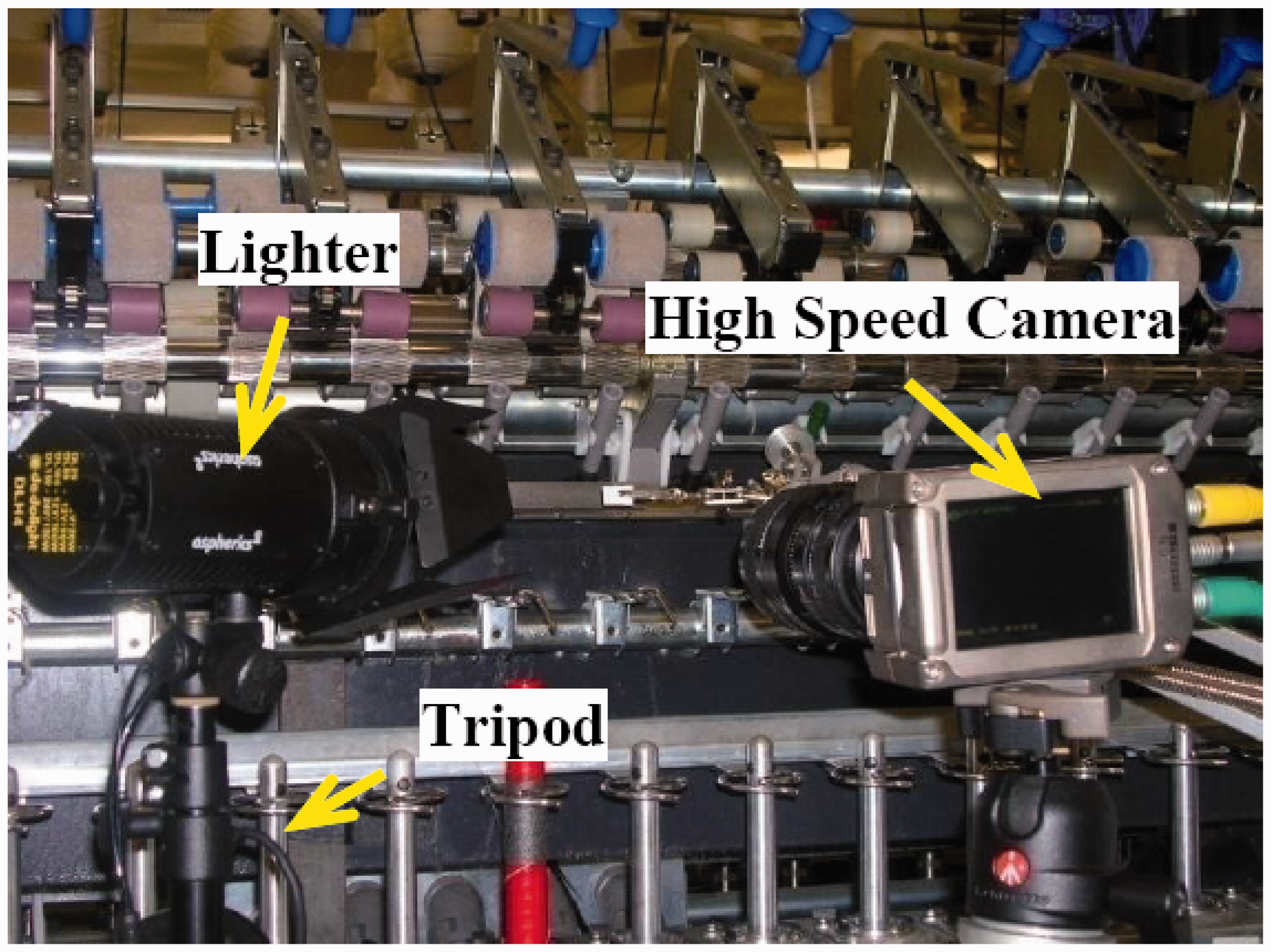
In order to obtain the twist from images, a black-white yarn was adopted. One black and unstained rovings with the similar count were fed into the back rollers simultaneously. As a result of twisting, the bundle of straight and parallel fibers was laid along the helix curve on the yarn surface, and yarn twist could be directly read by the interval of black and white fiber bundles. A scale paper of 1 mm × 1 mm size was put beneath the yarn to calculate the real length of one twist turn, as shown in Figure 3. The yarn twist can be derived by T = 1/h, where T represents the number of twist turns per unit length, h is the length of one turn of twist. Sixty images were used for the computation of yarn twist at each boundary. For each image, three readings were extracted, generating 180 raw data.
Determination of yarn twist from image.
Before measurement of the twist, the high-speed camera system was calibrated. Six twist levels were used for calibration and images of the twist were captured under a resolution of 512 × 512 pixels with a sampling frequency of 1000 frames per second. The measured values were compared with the results by using standard testing method ASTM D1423-02. As shown in Figure 4, twist measured by the high-speed photography method is approximately linear against the benchmark results by the standard method, which implies that the high-speed photography method can provide adequate accuracy and reliability for twist measurement. The relationship can be expressed by the linear regression equation as
Calibration of yarn twist.

The correlation coefficient is 0.999.
Similarly, the Hall speed sensor must be calibrated before online measurement of belt speed. The output signal corresponding to the rotating speed is analogy current ranging from 4–20 mA. After calculation, the relationship between output current and belt speed ratio was found. In the calibration process, six speed ratios were tested and the results are shown in Figure 5. The measuring value covers all the operational range in the experiment and the results can be expressed by the linear regression formula as
Calibration of the speed sensor.

The correlation coefficient is 0.999.
According to the aforementioned calibration results, it can be summarized that the proposed measurement system is suitable for measuring yarn twist and belt speed with excellent veracity and repeatability.
Yarn measurement
Yarn tests and standards

Results and discussion
Yarn twist in OA zone
As shown in Figure 6, three cases of sinusoidal variation of the false twist with different frequencies were implemented, and the corresponding twist redistributions in OA zone were examined and compared with theoretical calculations. It can be found that the predicted curves generally follow a similar trend to the experimental data, despite some deviations found with CV of about 10% to 15%, implying that simulated yarn twist in OA zone matches well with actual data.
Sinusoidal variation of the false twist and comparison of experimental data against predicted data in OA zone.
Measured yarn properties and final yarn twist
Measured properties of conventional yarns and yarns with and without belt speed variations

Four yarns with period 5 s and periodic variation of the belt speed of 10%, 20%, 30% and 40% were produced to study the effect of variation of false twist on yarn performances, as listed in Table 3. Within 30% periodic variation of false twist, the yarn properties were not significantly affected. When the variation increased to 40%, the mean tenacity and minimum tenacity of the sample were decreased by 0.39, and 0.65 cN/Tex, respectively, and the neps of SB-40% were also increased by 10.08%.
Simulation
The dimensionless model shows that lengths of divided zone path, false twist, belt properties, etc., influence the twist redistribution. In order to fully evaluate the twist variation, a series of numerical simulations are carried out in this section. Among the twist distribution in three zones, yarn twists in zone OA and BC are of particular interests since they have large influence on yarn structure and properties.
Twist redistributions in three zones
The parameters used for simulation below are Twist changes in three zones by sinusoidal variation of false twist.
Effect of system parameters on amplitudes of
and
Figure 8 shows the effect of oscillation frequency, false-twister position, and belt properties on the amplitudes of the twist in zone OA and BC. As the frequency increases, the twist oscillation becomes more and more damped. It can be seen from Figure 8(a, c) that at a higher The effect of 
Practically, the vibration frequency (in Hz) of friction-belt transverse motion is the rate in single digits, and the vibration frequencies of belt torsional and longitudinal motion are at least one order of magnitude higher than that of transverse vibration, and therefore the effect of friction-belt vibration on yarn twist variation in three zones is limited. On the other hand, the periodic variation of yarn diameter due to yarn unevenness is a promising factor that causes large twist variation. Take cotton spinning and wool spinning for example. The typical wavelengths of cotton-like fiber (33 mm) and wool-like fiber (66 mm) are 89 mm and 198 mm, respectively. The corresponding
Conclusions
This paper describes the effects of variations of false twist on process stability and resultant yarn quality in a modified ring spinning process. Although several basic simplifying assumptions have been necessary in order to make the analysis manageable, the findings have given a clear indication of the significant twist levels that can develop in the zones of the machine. Since twist in these zones can have a marked effect on the quality of the end product, these results are of some practical significance. It has been proved by the experiment that within 30% periodic variation in false twist, the yarn properties were not significantly affected. In other words, the current configuration and system parameters are stable and robust, as well as having a high tolerance for twist variations. From the simulation it has been demonstrated that belt oscillation has little effect on twist variation, and wool-like fiber causes large twist variation more easily in the spinning process than cotton-like fiber at the same condition. At the least, the results should give rise to a better comprehending of the mechanism of false-twister adopted in a ring spinning frame and provide method of calculating the practical levels of twist control required to reduce certain remarkable yarn faults.
Footnotes
Declaration of conflicting interests
The authors declared no potential conflicts of interest with respect to the research, authorship, and/or publication of this article.
Funding
The authors disclosed receipt of the following financial support for the research, authorship, and/or publication of this article: This research was funded in part through a research grant from the Research Grants Council of the Hong Kong Special Administrative Region, China (Project No: B-Q35S) and a postgraduate scholarship by the Hong Kong Polytechnic University.