



Abstract
This paper argues that the groove-wound licker-in racks’ spiral mounting leads teeth with an inclination angle to the rotating direction. Theoretical analysis of forces on the fibers is carried out when the inclination angle is 0 and θ: when the teeth enter the fiber layer, the inclination angle makes the pressure on fibers increases rapidly and leads to a stronger friction force on fibers. It also leads to increases in both contact area and the wrap angle of the fiber around the teeth. This article also uses ANSYS Explicit Dynamics to simulate the fiber assembly carded by a tooth, when the inclination angle is 0°, 1° and 2°. When the inclination angle of the model is 1°, its fiber deformation is 1.35 times that of 0°; its elastic strain and stress concentration coefficient are 1.40 times than that of 0°; when the inclination angle of the model is 2°, its fiber deformation is 1.72 times than that of 0°; its elastic strain and stress concentration coefficient are 2 times than that of 0°. As with the inclinations increasing, the fiber deformations increase in time grow from 0.0634 and 0.08477 to 0.10584. The simulation also shows that when the tooth works on the fibers, there is a sudden compressive stress on fibers and then this pressure transfers with time. From all of the above, the inclination angle on licker-in teeth results in larger strain and deformation on fibers, so that this inclination angle should be decreased as much as possible in practice.
Keywords
The main role of the licker-in is the initial carding and cleaning. The licker-in zone determines the degree of pre-opening and the later carding processes, such as the carding efficiency between the cylinder and flats, and has influence on the quality of carding sliver and fiber damage directly.1–3 The teeth on the licker-in puncture the fibers on the feed plate and divide the fiber layer. The friction forces on fibers are from both the teeth and the surrounding fibers, and these forces result in fibers being caught and carded by the teeth and delivered to the cylinder. These fibers are carded by the teeth in the region between the feed plate and licker-in and about 70–80% of the tufts are carded into individual fibers.
4
Therefore, the friction forces on the fibers are essential for the working of the licker-in. On the licker-in, the groove-wound clothing is mounted along cylindrical spiral lines (Figure 1). In the expanded diagram of the cylindrical spiral lines on the licker-in, the diameter of the licker-in is not so large that there is a significant spiral angle θ. The relationship between these parameters in Figure 1 is Inclination angle in the expanded diagram of the cylindrical spiral lines, where d is the licker-in diameter (mm), h is the pitch of the cylindrical spiral (mm) and θ is the inclination angle (°).
At the aspect of the single tooth, the inclination angle makes the teeth stand aslant on the licker-in. Therefore, there is an inclination angle between the tooth body and the moving direction of the licker-in (Figure 2). The angle is the same as the spiral angle mentioned above. This inclination angle causes the teeth to squeeze into the cotton layer obliquely, rather than moving perpendicularly to the fibrous layer.
Schematic diagram of the teeth carding fibers with an inclination angle θ.
Experiments on the relationship of the card sliver properties and the parameters of the licker-in, especially the speed, have been carried out by many researchers.6–8 There are theoretical studies on the carding effect, which are mainly based on the relationships of the single fiber configurations or hooks and the carding parameter.9,10 For the mechanical analysis, some studies worked on the mechanical analysis of multi-fiber carding study, and they simplified the card clothing as rough wall. 11 However, the tooth shape has a significant effect on the carding effect, and in recent years the new type of card clothing application has been proved to be of significant benefit. 12 Therefore, the carding effect of the teeth configuration on the fiber assemblies still needs more investigation. Kuo et al. 13 built a dynamic mathematical model on the cotton web of the roller carding machine, and its considered parameters included clothing tooth angle and the friction forces. However, in this research, the angles are related to the fiber transfer between rotating cylinders and rollers, instead of the force between teeth and fibers.
This paper discusses the effect of the teeth spiral inclination in terms of the interaction between teeth and fibers. The spiral inclination angle of the teeth is very small under the actual conditions, and the interaction between the teeth and the fiber assembly is dynamic and very complicated. Therefore, this study uses mechanical analysis in the theoretical discussion. Besides, the explicit dynamics solver in ANSYS Workbench has also been applied for validation.
Theoretical discussion
Model building
Firstly, the mechanical analysis method is used to model and analyze the force of the fiber assembly on the tooth with different inclination angles. Before modeling, the shape of the tooth is simplified. The real teeth and the simplified tooth geometry are shown in Figure 3. During the carding process, the fibers are gripped by the work face; thereby, we choose the cross-section of the middle of the tooth in Figure 3(b) and make analysis of it. In this cross-section, the length is a and the width is b. Figure 4(a) and (b) show teeth cross-sections with inclination angles of 0° and θ, respectively.
Simplified tooth. (a) Real teeth. (b) Simplified teeth. Teeth cross-sections with different inclination angles (a) Inclination angle is 0°. (b) Inclination angle is θ°.

Initial effect of teeth on the fiber assembly
The fibrous layer is pressurized to produce pressure on the working face of the tooth. In Figure 4, this pressure refers to a positive pressure on unit length on the edge of a, which is signed as q. In this figure, l1, l2 are the projection width of the cross-section when the inclination angles are 0°and θ°. Based on equations (1) and (2), it can be known that l1 is smaller than l2. Then friction forces on the working faces of these two models are f1 = μql1, f2 = μql2 (μ means the friction coefficient), respectively. Angle θ is about 2°, and the square of sinθ is too small to take into consideration when we compare f1 and f2. It is obvious that f1 < f2. That is to say, the presence of the inclination angle causes the length of the interaction between the tooth and the fibers to increase, which results in an increased friction force and enhanced griping effect by the tooth. Therefore, the tooth is able to catch fibers more intensively or more fibers at once, which not only reduces the carding quality and the removal efficiency, but also increases the tooth load of the subsequent carding apparatus, such as the cylinder


Also in Figure 4, D1, D2 are the center distances between the two lines of the groove on the licker-in. So, the D1 and D2 should be the same. d1, d2 are the distances of the channels between two adjacent lines of teeth. The inclination of the teeth also reduces the width of the channel between adjacent teeth, which means d1 > d2. Therefore, the larger the inclination angle is, the smaller the channel distance is. Taking a small length △y along the height of the tooth, when the inclination angle is 0°, the channel distance is
Effect of inclination on a single fiber
After the initial stage when the licker-in teeth insert themselves into the fiber layer on the feed plate, the teeth continue to impact on fibers. Their interaction with the fibers is shown in Figure 5, which shows the forces on a single fiber when the tooth is at different inclination angles. The fibers are in bending shape and hooked by the tooth. P1 and P2 are the tensions on two ends of fiber without considering the friction forces from the two sides (b in Figure 4) of the tooth separately. As the fibers move around the working face of teeth during carding, the tension of P1, P2 can satisfy the description of the relationship between the friction forces when the rope is around the cylindrical pile in the Euler Formula (equation (3)).
14
In the Euler Formula, P1 is the tension force of the point where the rope encounters the cylindrical pile, while P2 is the tension force of the point where the rope starts to leave the cylindrical pile
Force analysis of fiber movement around the tooth (a) Inclination angle is 0° (b) Inclination angle is θ.


During the movement of the needle, the fiber is held by one end and the other end is wrapped along the working face of the tooth, then the fiber bundle can be split. Selecting the teeth cross-sections in Figure 3 enables one to simplify the forces on fibers, as shown in Figure 5. In this figure, the friction forces on the fiber when it moves around the tooth are shown as Q1, Q2. The forces on the fiber are shown in Equations (4) and (5).
As we mentioned before, the tooth is inclined so that the contact length increases, which means l1 < l2; the density of the fiber assembly between adjacent teeth increases, which means N1 < N2, T1 < T2; the wrap angle of fiber to the tooth is larger as the tooth is slant to the fiber axis, because there is an additional wrap angle ψ for Q2, β < (ψ + β); therefore, Q1 < Q2.
Besides, due to the presence of inclination angle θ, the tooth works against the fiber bundle obliquely with one of its edges initially; when the inclination angle is 0°, the tooth works against the fiber bundle vertically with its working face. It is easy to see that edges bring more intensity of pressure and damage to fibers than the face. This view point can be supported by the research of Xu and Zhou, 15 which discussed and tested the fiber damage by the different edges of the tooth in the process of carding. In that research, it was pointed out that teeth edges have a cutting action on fibers. So, the inclination does undoubtedly exacerbate the fiber damage.
Explicit dynamic simulation
Based on the qualitative analysis above, the presence of the inclination leads to a larger friction force on fibers, thereby increasing the damage to the fiber. The mechanical analysis above can only be used for qualitative analysis. The inclination angle is very small under the actual conditions (about 2°), and the interaction between the licker-in and the fiber assembly is more complicated. So, explicit dynamic simulation is used in this article for intuitive data and the difference variance by the small angle change.
Characteristics of the licker-in working process
The linear velocity of the licker is about 100 times the speed of the cotton lap.
5
The process in which the tooth works on the fiber assembly can be approximated to the high-speed impact issue: in Figure 6, when the tooth on the licker-in continues to rotate, the distance of the tooth top is becomes closer and closer; therefore, it is firstly a process in which the tooth is being inserted into the tooth. Because the forces and deformation of the fibers undergoes the most significant changes in this region, the force analysis should be made in this simulation. In this study, the time used by a single tooth to go through the fiber assembly is about 0.1 ms. The inclination angles are set as 0°, 1° and 2°, respectively. These three situations are named model 1, model 2 and model 3, respectively.
Geometric model.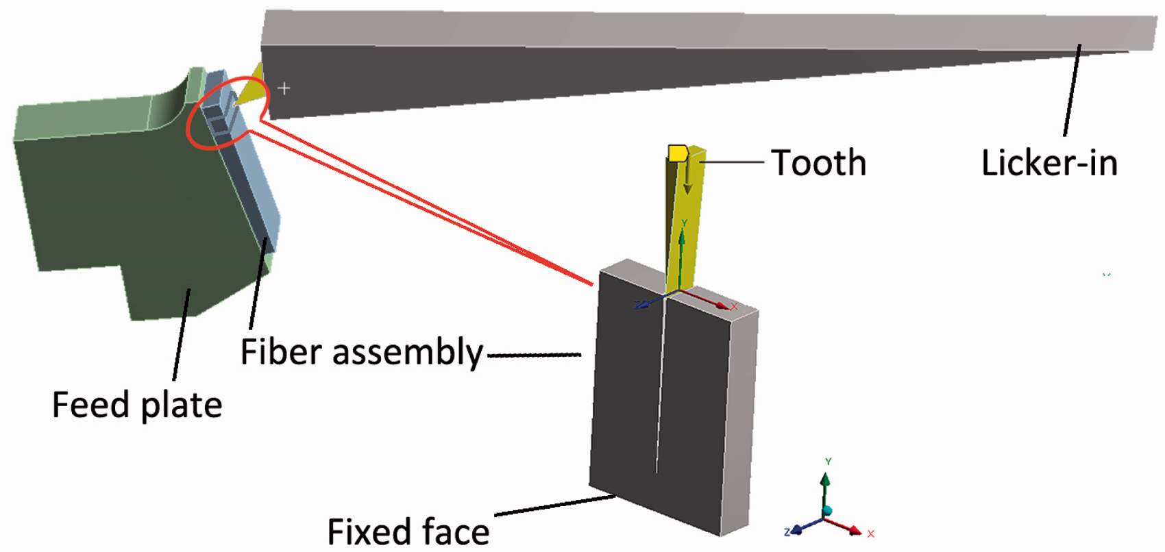
Model simplification
Geometric model
Before the simulation, the cross-sections of the tooth are simplified as isosceles triangles (Figure 6). A small fiber block is selected from the feed plate, with a size of 4 mm × 5.5 mm × 0.5 mm. A narrow slit is also made in the fiber block to represent the space between fibers and make it easier for the tooth to go inside in the simulation. The slit has a height of 4.5 mm and a width as small as 0.05 mm. The fiber assembly is simplified to one block of fiber as in this region, and the fibers are compressed and close to each other. In this research, what is of concern is the differences of force resulted by the inclination angles; therefore, the trajectory of the tooth can be simplified as a linear motion.
Material property
The material of the tooth is defined to be structural steel as a rigid body, while the fiber block is defined as a flexible body. The elastic recovery rate of the fiber layer is about 80% when it leaves the nose of the feed plate. 1
Meshing and setting
The relevance of the whole mesh is set as 100. The mesh for the tooth and the fiber block are applied with the sweep method, and the mesh of the slit area is finely divided, as shown in Figure 7. The number of nodes is 53,352.
Meshing.
Analysis of results
Stress and strain distribution
After carding by the tooth, the fiber block is divided into two sections around the tooth (Figure 8). Figures 9–11 show the contours for three indicators at these angles of 0°, 1° and 2°, separately. These three indicators are the material total deformation, principal elastic strain and maximum principal stress.
The fiber block shape change. Total deformation contour for models 1–3.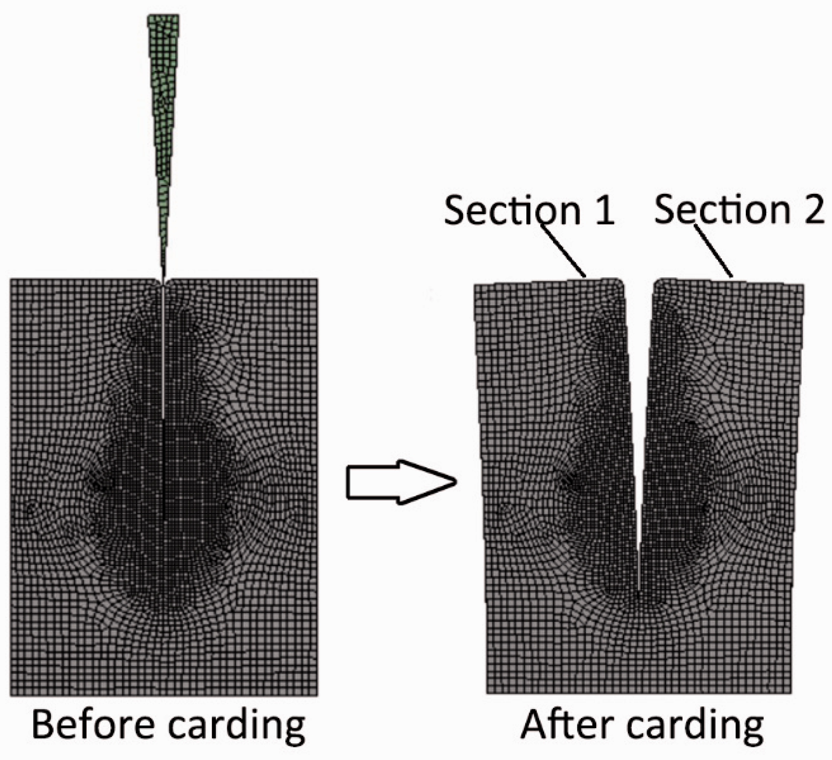

According to the comparison of the stress, strain and stress contours of the fiber block, it can be clearly seen that when the angle of the needle tooth is 0°, both sections 1 and 2 have the same distribution on stress and strain; when the inclination angle is 1° and 2°, the two sections of each fiber block have different distributions: one section (section 1) shares a similar stress and strain distribution with that of 0°, but the other (section 2) is total different. This is because the inclined tooth brings more pressure on one side but less pressure on the other, and this brings many different mechanical consequences.
To be specific, in terms of the total deformation contour on the fiber block (Figure 9), the larger the inclination angle is, the larger the deformation quantity is. Compared with the deformation of model 1(its deformation is about 0.186 mm), the maximum deformation of model 2 (0.252 mm) is 1.35 times than that of model 1, while the maximum deformation of model 3 (0.319 mm) is 1.72 times than that of model 1. For model 2, the deformation quantities of its left-hand fiber block sections (section 1) are in the range of 0.25 –0 mm, and the other section on the right-hand side (section 2) is in the range from 0.14 to 0 mm. Therefore, in model 2, the fiber block shows significant difference and unevenness in deformation. In model 3, this difference is even larger (from 0.32 to 0 mm for section 1, and from 0.071 to 0 mm for section 2). This phenomenon means that the inclination angle leads to uneven and larger deformation on the fiber block, which causes more fiber damage.
For the principal elastic strain contour (Figure 10), in model 1, both of the two sections of the fiber block share the same elastic compression strain. When the tooth is inserted into the fiber block, the fiber assembly is compressed. This is why the total deformation values are all smaller than 0 in this figure. The absolute value of elastic strain decreases from the narrowest place of the slit to the widest place of the slit. When the inclination angle is 1° in model 2, the distribution of compressive strain on section 1 of the fiber block is similar to that of model 1, and the maximum absolute value of its elastic deformation degree is about 1.4 times that of model 1; the compressive strain on section 2 is smaller than that of section 1, because the tooth is inclined away from this section. When the inclination angle is 2° in model 3, the maximum absolute value of its elastic deformation degree is 2 times that of model 1. The elastic strain of model 2 is larger than model 1 and smaller than model 3. This means that the elastic strain is also relative to the inclination angle and the inclination results in fibers being more compacted.
Principal elastic strain contour for models 1–3. Maximum principal stress contours for models 1–3.

For the maximum principal stress (Figure 11), it is seen that when the tooth tip is inserted into the gap of the fiber block, all the models show stress concentration at the narrowest place. The narrowest place is the place where fibers are entangled. The stress concentration coefficient a is calculated with equation (6). The higher the concentration coefficient A is, the more intense the stress value changes. When the inclination angle is 0° in model 1, the stress concentration factor a1 is about 5, and when the inclination angle is 1° and 2°, the stress concentration coefficients A2 and A3 are about 7 and 10, respectively. So, the inclination angle makes the stress concentration of the fiber block be more intensified, and the fiber damage at the stress concentration point is enhanced

Stress and strain varying over time
For comparison, the curves of the three indexes varying over time are plotted in Figures 12 and 13. These indexes are total deformation, maximum comprehensive strain and maximum comprehensive stress. It can be seen from the figures that each index of the fiber block shares basically a similar variation tendency in different inclination angles over time.
Total deformation–time curve. Stress–time curve (a) and strain–time curve (b).

In Figure 12, it can be reflected that the fiber block is deformed by the pressing of the tooth during the insertion of the tooth into the gap, and the overall deformation is linearly changed with the entry of the needle teeth. Therefore, the greater the inclination angle, the greater the change rate of the whole deformation. The slopes of the total deformation and time are calculated by the least squares method (Equation (7)). They are calculated as 0.0634, 0.08477 and 0.10584 for models 1–3, respectively. Therefore, the deformation changes intensely with a larger inclination angle. This is due to the fact that the tooth occupies more space when the licker-in rotates as the inclination increases. Thereby, the overall deformation of the fiber block increases significantly

In the compressive stress curve of Figures 13(a) and (b), their absolute values increase in the beginning then decrease and increase finally. This reflects that when the tooth is inserted into the gap of the fiber block, the fibers are forced by the compression stress on both sides of the tooth.
To be specific, the absolute values of the compressive stress and strain both reach the maximum at
From
Overall, in the cases of three inclination angles, the smaller the inclination angle of the tooth, the smaller the overall force and the overall deformation of the fiber block. The theoretical analysis of the cross-section we discussed above shows that the projection breadth of the tooth increases with inclination and leads to a higher pressure between fibers. So, the simulated results agree with those of the theoretical analysis. Therefore, in practice, the inclination angle should be maintained as small as possible to reduce the fiber damage and short fibers. Further experiments should be carried out to verify this assumption.
Conclusion
In this paper, the inclination angle of the licker-in card clothing used in the current production is theoretically analyzed. It is considered that the presence of an inclination angle leaves the fiber assembly with smaller space, so that the pressure and friction force on fibers increase dramatically and the fibers are easily damaged. Besides, based on the Euler Formula, the inclination angle also results in a larger wrap angle, which made the friction forces on the fiber increase. Finally, the fiber is first in contact with the edge of the inclination tooth, and this edge contact can cause fiber damage.
Explicit dynamics simulation is also used to establish the digital model of the fiber block being carded by the tooth with inclination angles of 0°, 1° and 2°. It is proved that for a fiber block carded by the tooth with inclination angles, its deformation and stress are in uneven distribution. As the inclination angle increases from 0° to 2°, the total deformation increased 1.7 times. Besides, the changes of elastic strain and the stress concentration are more significant: the absolute value of elastic strain increase 2 times, and the stress concentration coefficient grows from 5 to 10. All of the above phenomena lead to more fiber damage. Therefore, the simulation can validate the theoretical analysis.
When the time is taken into consideration, fiber deformations are in positive correlation with time, and the slopes increase from 0.0634 and 0.08477 to 0.10584. In addition, it also shows that when the tooth contacts with fibers, there is a sudden intense compressive stress initially and then its value decreases because of stress transfer.
The above results show that the inclination angle of 0° is the most favorable for the fiber quality. Subsequent studies will continue through the actual design and improvement of the licker-in card clothing, as well as the experiment to verify the theoretical results in this paper.
Footnotes
Declaration of conflicting interests
The authors declared no potential conflicts of interest with respect to the research, authorship and/or publication of this article.
Funding
The authors disclosed receipt of the following financial support for the research, authorship, and/or publication of this article: This work was supported by the Fundamental Research Funds for the Central Universities (Grant Number CUSF-DH-D-2018030) and National Science and Technology Major Project (Grant Number 2017YFB0309100).