



Abstract
This paper studied the fiber movement in vortex spinning based on the flexible fiber finite element model, according to the theoretical mechanical analysis of the vortex spun yarn forming process. The finite element simulation and analysis of the different trajectories of free-end fiber in vortex spinning under different process parameters were carried out. The influence of the fiber count, fiber bending stiffness and nozzle pressure on the fiber transfer and distribution was analyzed and verified by experiments of tracer fiber and yarn slicing. The numerical simulation and the experiments’ results show a consistent correlation of different process parameters and fiber movement, such as the fiber diameter increasing, the fiber bending stiffness increasing, the nozzle pressure decreasing, and the fiber tending to get a smaller twist angle and becoming more easily distributed in the center of the yarn. This paper provides a theoretical basis for the structure design of vortex spun yarn and the production practice of vortex spinning.
In 1995, the Murata Company in Japan first proposed vortex spinning technology, which set MVS (Murata Vortex Spinning) as the representative. The spinning principle of vortex spinning1–2 is that the trail end of the fiber rotates close to the surface of the hollow spindle under the action of a high-speed rotating flow, wrapping core fibers into yarn. In 1999, Rozelle 3 and Gray 4 described the spinning process and the yarn mechanism of vortex spinning system in detail. Among the new spinning technology, the vortex spinning is one of the fastest. Li 5 studied the effect of the nozzle hole pressure and the distance from the guide pin to the hollow spindle top on polyester yarn tensile performance by experiments. Pei et al.6–8 came up with the correlation of the hollow spindle cone angle and the yarn performance. Zou et al.9–10 recognized the relationship between the nozzle structural parameters, the velocity of the air flow at nozzle hole exit and the airflow characteristics by numerical calculation. Oxenham 11 used an untwisting way to verify the structure of vortex spun yarn. His studies have shown that the space distribution and morphological conformation of the fiber in the yarn is consistent with the movement law of the free-end fiber in the spinning process. Kyaw et al. 12 proposed the relationship between the proportion of core fiber, wrapped fiber and floating fiber in vortex spun yarn and the yarn performance, by comparing the structure of ring yarn, rotor spinning yarn and MVS yarn. Different process parameters such as fiber count, fiber bending stiffness and nozzle pressure will impact directly on the fiber trajectory under the vortex airflow of high velocity in the twisting chamber, then impact on the yarn structure and performance. However, there are fewer researchers studying the fiber trajectory during the vortex spun yarn forming process. Han et al.13–14 established the fiber finite element model based on the spatial elastic thin-rod unit, and deduced the static equilibrium equation of that, which presented an effective and feasible theoretical model and method for the study of fiber movement. In this paper, the trajectories of free-end fiber in vortex spinning under different fiber count, fiber bending stiffness and nozzle pressures are simulated based on the elastic thin-rod finite element model of flexible fiber. The nonlinear geometric large deformation of the free-end fiber is studied by the method of step-by-step loading and successive approximation. According to experiments of tracer fiber and yarn slicing, the influence of different fiber count, fiber bending stiffness and nozzle pressures on the fiber transfer and distribution is analyzed and verified. This paper will present the correlation of different process parameters and fiber movement, which is helpful to guide the structure design of vortex spun yarn and the production practice of vortex spinning.
Theoretical mechanical analysis of vortex spun yarn forming process
Data of airflow velocity extraction
During the vortex spinning process, the compressed air through the nozzle holes goes tangentially into the twisting chamber of the main nozzle, along the inner wall of the nozzle and flows along the chamber formed by the outer wall of the hollow spindle and the inner wall of the nozzle chamber. The vortex formed flows downwards spirally. The compressed air generates the negative pressure at the entrance of the hollow spindle. The fiber bundle is sucked into the hollow spindle along the spiral curved surface and the guide pin after drafting. The front part of the fiber is formed of the yarn core. The fiber becomes the fiber of free end after passing into the hollow spindle. Under the high-speed rotating airflow, the free end of fibers lay flat on the wall of the still hollow spindle, presenting an umbrella shape. The free end of fibers slide on the wall of the still hollow spindle and wrap the core fiber. Finally the yarn is formed.
In the twisting chamber, the velocity of vortex airflow could be resolved into three components along the axial, tangential and radial direction. The data extracted of the vortex airflow velocity in the twisting chamber by computational fluid dynamics technology are shown in Figure 1. The nozzle pressure in the simulating model was 0.55 MPa.
15
According to Boltzmann (Boltzmann model) and ExpDec1 (index simulation), the tangential velocity VTa, radial velocity VRa and axial velocity VAa in Figure 1 were derived according to equations (1), (2) and (3) using Origin 8.5 software. The tangential velocity VTa, radial velocity VRa and axial velocity VAa under different nozzle pressures could be derived by the same method.
Velocity of airflow in the position of fiber axis.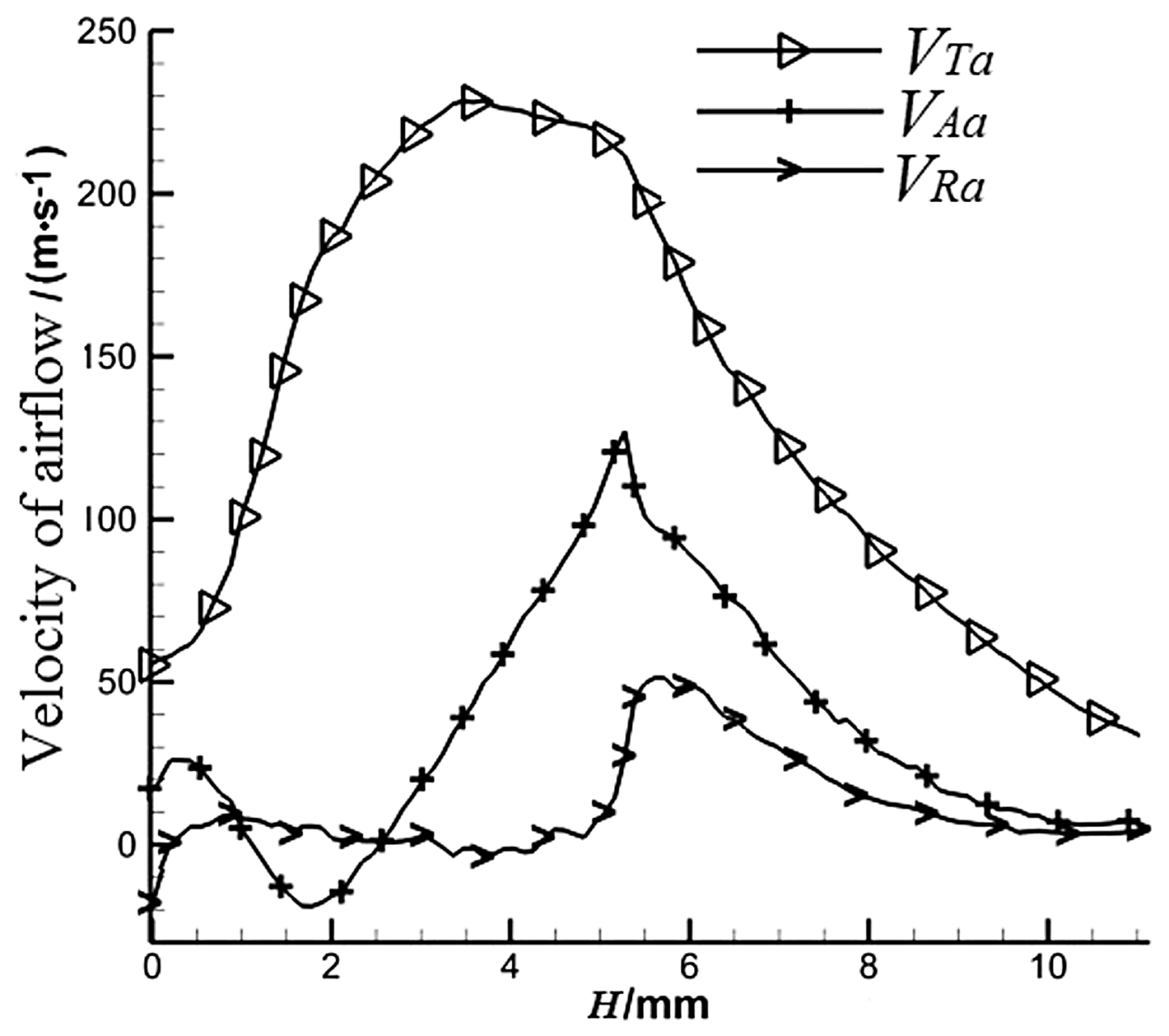



Theoretical mechanical analysis of airflow force
Based on the vortex spun yarn forming process, the high-speed rotating airflow in the twisting chamber has a series of complex forces on the fiber. In order to analyze the fiber transfer and distribution during the vortex spun yarn twist forming process concisely, this research assumes that the forces are acting in the yarn uniformly. The tangential velocity VTa, radial velocity VRa and axial velocity VAa generate the tangential, radial and axial forces FT, FR and FA, as shown in Figure 2. Based on the interaction of the fiber and airflow in the twisting chamber, the fiber infinitesimal segment is defined as a rigid round rod rotating around the hollow spindle.
15
Forces analysis of the free-end fiber.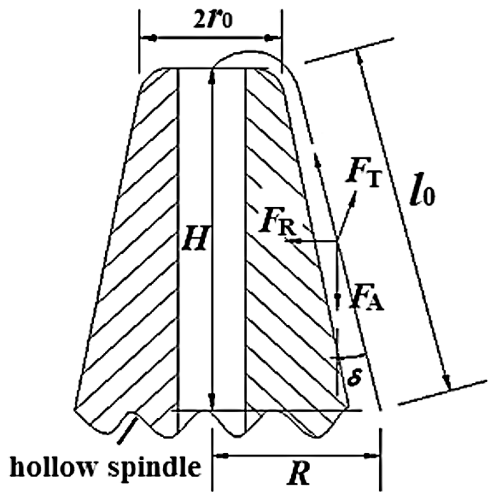
According to the formula of flow around the cylinder,16–17 the tangential force FT applied on the fiber along the lateral wall could be derived as



Because the airflow rotates downward around the wall of the hollow spindle, the force FA applied on the fibers along the hollow spindle axis is

The radial airflow allows fibers to be attached to the wall of the hollow spindle. According to the formula of flow around the cylinder, the radial force FR on fibers is

When the free-end fiber rotates on the surface of the hollow spindle, the centripetal force FL on fibers can be obtained



The free-end fibers lodge on the hollow spindle outer surface. During the fibers’ rotating process, the fibers are in contact with each other. Between the fibers, there occurs a relative movement and a friction resistance Ffm. The calculation formula of the friction Ffm is



Dynamic finite element model of flexible fiber
Establishment
The fiber is a kind of elongated body with large aspect ratio, elasticity and flexibility. The actual movement law of the free-end fiber in the high-speed twisting airflow field is very complicated, involving translation, rotation, bending, stretching and so on. Han et al.13–14 established the fiber finite element model, and deduced the static equilibrium equation of the spatial elastic thin-rod unit, which presented an effective and feasible theoretical method. In this research, the whole single fiber is equally divided into n + 1 independent elastic thin-rod units, and a node is set at the center of the midpoint cross-section of each elastic thin-rod unit.
Dynamics analysis
In order to achieve the feasibility and rationality of the calculation about the nonlinear large deformation problem of the free-end fiber, the fiber finite element model based on the spatial elastic thin-rod unit is established such as shown in Figure 3.13–14 Space diagram of fiber rigid microsegment.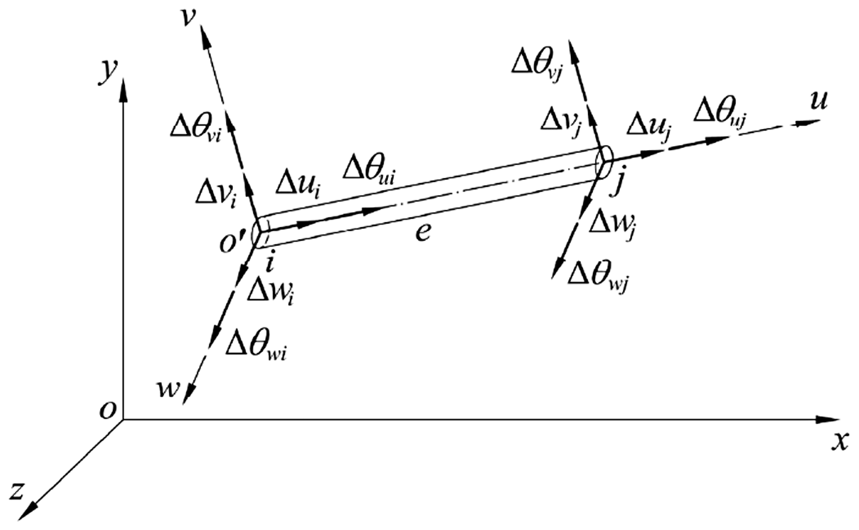
The freedom degree of the external force on the node is converted into the freedom degree of the fixed total coordinate system, and then expressing the kinetic motion differential equation

The freedom degree of the external force on the rod is converted into the freedom degree of the fixed total coordinate system, and then expressing the external force equation

The total finite element analysis is carried out by combining the infinitesimal rigid segment nodes and the elastic thin-rod elements together

Numerical simulation and analysis
Initial parameters
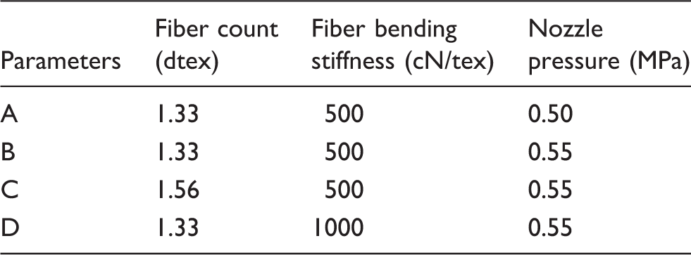
The process of fiber transfer in the vortex spun yarn formation could be simplified to the model shown in Figure 4. The initial parameters of the fiber model in ANSYS software is shown in Table 1.
20
The figure is a partial cross-section, in which the large cylinder is a fixed twisting chamber. The inner center cylinder CD is the central fiber strand, which is regarded as a fixed rigid body relative to the small cylinder AB. The internal eccentric small cylinder AB is the fiber, which is wrapping around the central fiber strand during its transfer process. The fiber is seen as a flexible rod, with its A-side fixed, and B-side free. The airflow in the twisting chamber rotates at a high speed around the x-axis and moves at a low speed along the x-axis. The fiber will wind on the central strand under high-speed airflow. The finite element method is used to simulate the transfer process of the fiber under the airflow during the vortex spun yarn formation. The initial position of the fiber AB is Z = 0.5 mm; the length of the fiber AB is 19 mm; the shear elastic modulus G of the fiber AB is 10.4 cN/tex; the initial velocity of the fiber AB is 0. The radius of the fiber strand CD is 0.3 mm; the length of the fiber strand CD is 19 mm. The radius of the twisting chamber is 3 mm; the length of the twisting chamber is 25 mm. The density of the air inside the twisting chamber is 1.25 kg/m3; the velocity of the airflow inside the twisting chamber is extracted and derived by computational fluid dynamics technology and converted into the forces acting on the fiber finite element model according to equations (1), (4), (5), (16) and (17).
Space diagram of vortex spun yarn forming process model. Initial parameters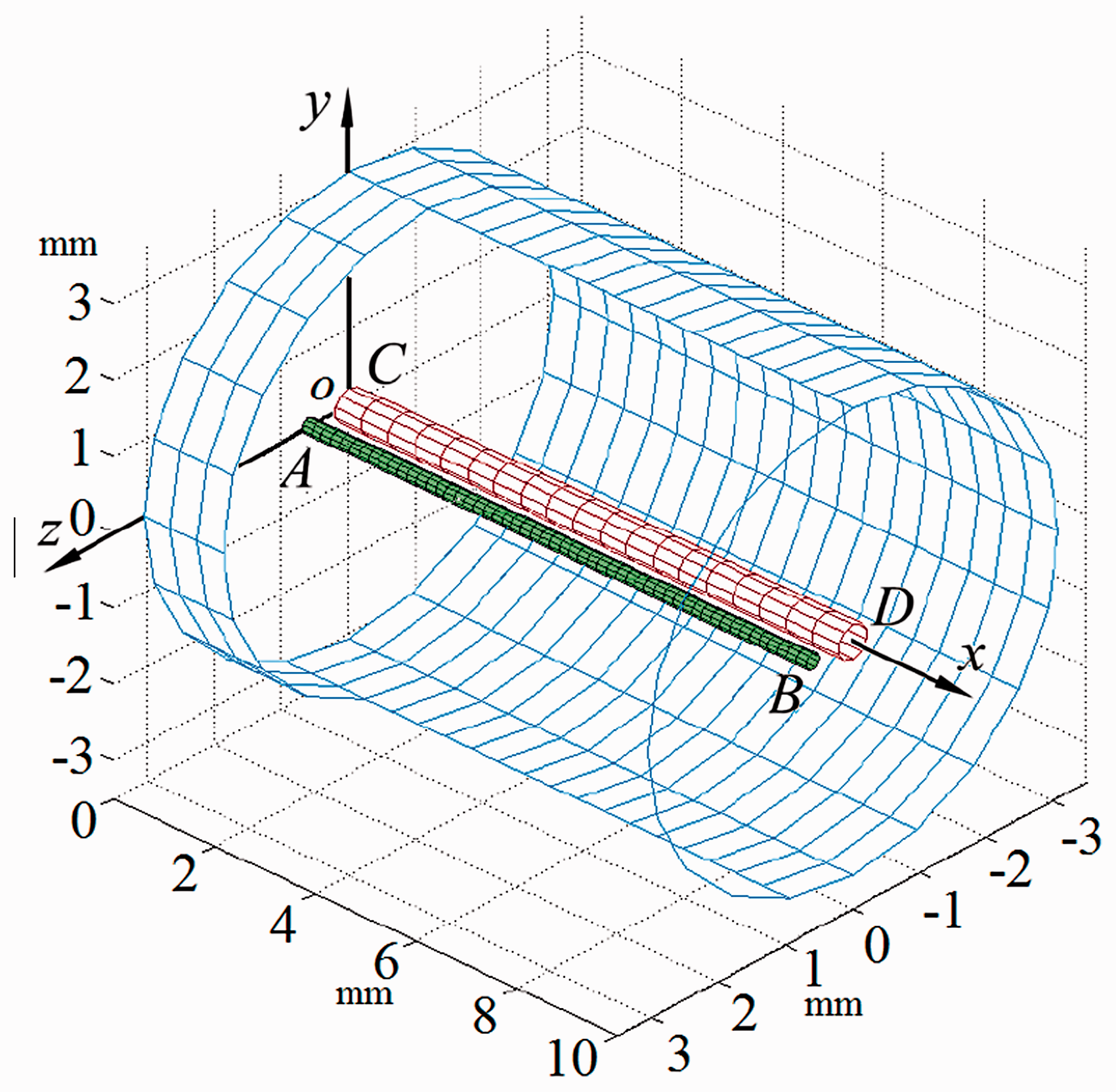
Boundary constraints
The working process of the numerical calculations is an adiabatic condition, and the fluid is high-speed unsteady ideal gas which is compressible. During the actual fiber wrapped process, we considered the fiber movement resistance from the stand, the other fibers and the airflow. The size and direction of the resistance will change with the fiber movement position changing, which could not be specifically determined in the model. We directly calculated the resistance effect to the airflow velocity reduction, so the airflow velocity in the simulation is the final result of the actual airflow velocity minus the resistance reduction value. To be on the safe side, we chose the minimum value within the normal range of resistance as −5%. The size of the fiber AB division unit is 0.5 mm the number of the fiber AB division units is 200, which is shown in Figure 5.
Fiber finite element model.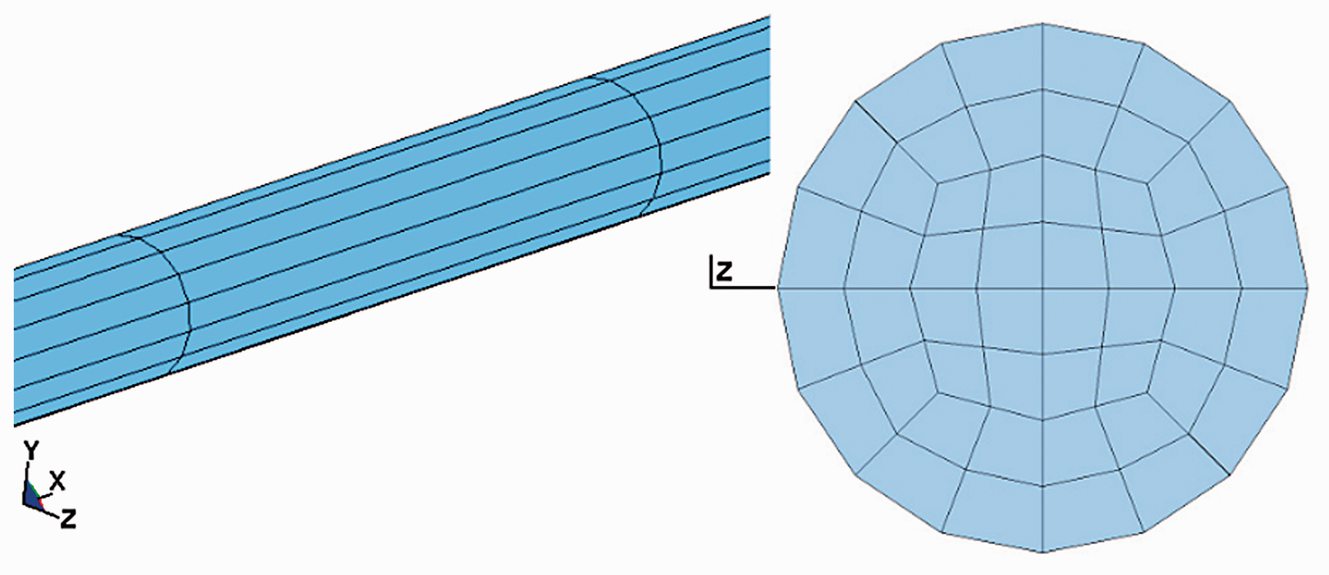
The A-side of the fiber AB is a fixed constraint. The contact constraint between the fiber, the strand and the twisting chamber inner wall is treated by the penalty function method in this paper. For each node, we first construct a repulsive force between the fiber, the strand and the twisting chamber inner wall, which increases rapidly when the distance between them is closer, and quickly decays to zero when the distance between them is more than a certain distance. The penalty function method prevents the fiber and the strand embedding in each other. The repulsive force can be seen as a positive pressure between the fiber, the strand and the twisting chamber inner wall, according to the following formula

Solving methods
In order to ensure that the position of the elastic thin-rod unit in the local coordinate system is close to the exact position of the elastic thin-rod unit after the large displacement, this paper adopts the load incremental step loading method. The load is divided into N loading steps from zero, which ensures that the load increment for each step is a small amount. For the first load step at which the load is zero, the position of the entire non-loaded state of the elastic rod unit is taken as the initial position. The second load step at the initial position is taken after establishing a local coordinate system. The displacement of each elastic rod unit under the load is solved by the element stiffness equation established under the small displacement condition, and the new position of the whole fiber after the first deformation will be obtained. For any N loading step calculation, the position of the elastic rod unit in step N–1 is taken as the initial position. As long as the load increment for each loading step is a sufficiently small amount, the displacement of each elastic rod unit obtained relative to the local coordinates must also be a small amount, thus ensuring that the element stiffness equation is accurate. In this paper, the simulation of the fiber motion under the airflow during the air-assisted twisting process is subjected to the laws of conservation of mass, conservation of momentum and conservation of energy. When
Simulation results and analysis
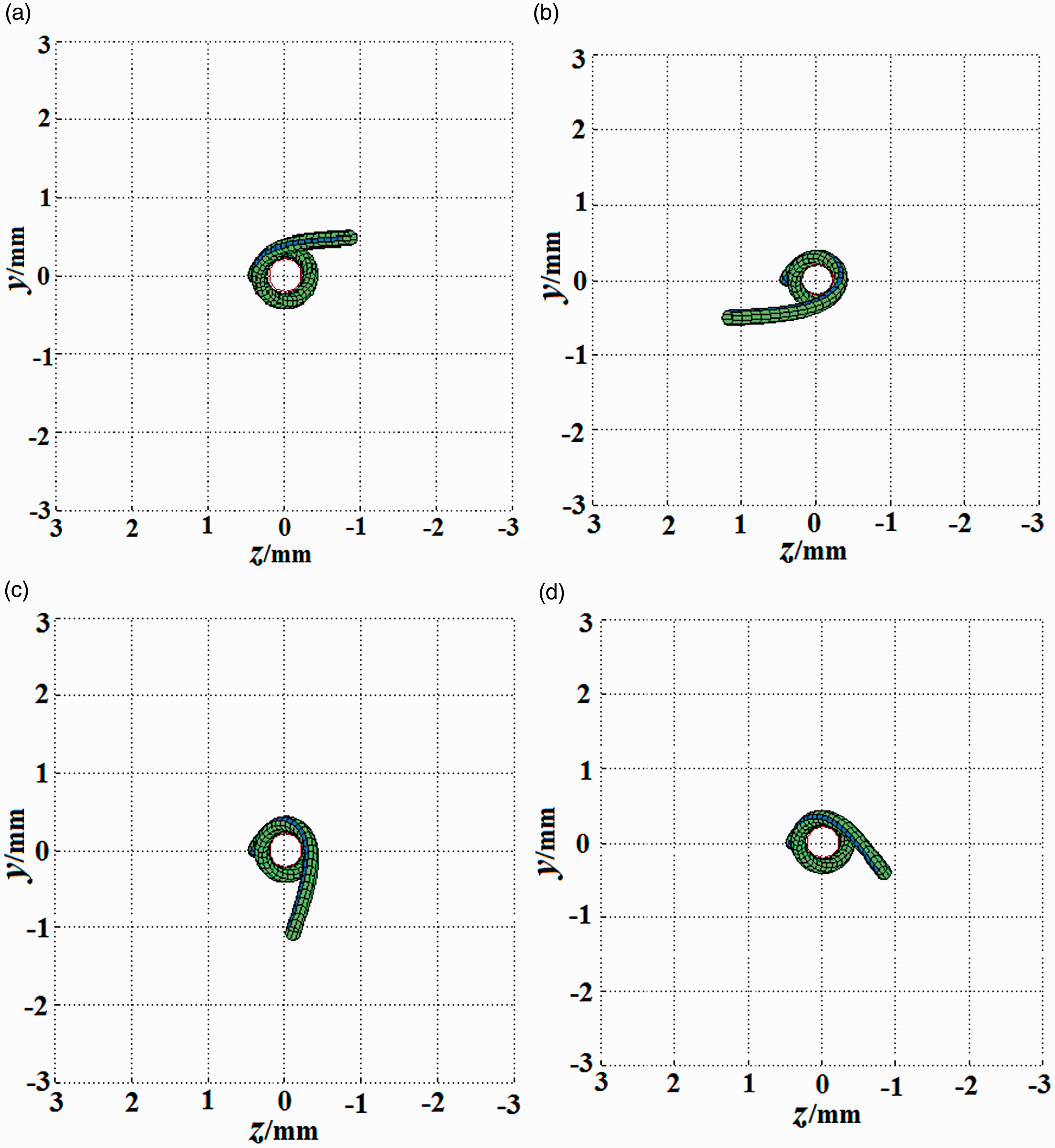
When t = 3 ms, the simulated fiber-wrapped side views of A, B, C and D during the vortex spun yarn forming process are shown in Figure 6, and the simulated top views of A, B, C and D during the vortex spun yarn forming process are shown in Figure 7. When the nozzle pressure increases, the velocity of the airflow in the twisting chamber will increase and the force generated by the airflow will increase. When the count and bending stiffness increase, it is more difficult for the flexible fiber to bend. During the vortex spun yarn forming process, the twist angle of the free-end fiber wrapped on the strand is the angle between the yarn axis and the fiber axis; as the bending deformation of the free-end fiber increases, the twist angle of the free-end fiber will increase. Comparing the simulation results of A and B, when the nozzle pressure increases, the twist angle of the free-end fiber increases. This is because when the flexible fiber has the same count and bending stiffness, the force on the free-end fiber is larger and the bending deformation of the free-end fiber is larger. Comparing the simulation results of B and C, when the fiber count increases, the twist angle of the free-end fiber decreases. This is because when the flexible fiber has the same bending stiffness and is under the same force, the free-end fiber is more difficult to bend with the larger count. Comparing the simulation results of B and D, when the fiber bending stiffness increases, the twist angle of the free-end fiber decreases. This is because when the flexible fiber has the same count and is under the same force, the free-end fiber is more difficult to bend with the larger bending stiffness.
Side view of fiber-wrapped form. (a) Fiber-wrapped side view of A at t = 3 ms. (b) Fiber-wrapped side view of B at t = 3 ms. (c) Fiber-wrapped side view of C at t = 3 ms. (d) Fiber-wrapped side view of D at t = 3 ms. Top view of fiber-wrapped form. (a) Top view of A at t = 3 ms. (b) Top view of B at t = 3 ms. (c) Top view of C at t = 3 ms. (d) Top view of D at t = 3 ms.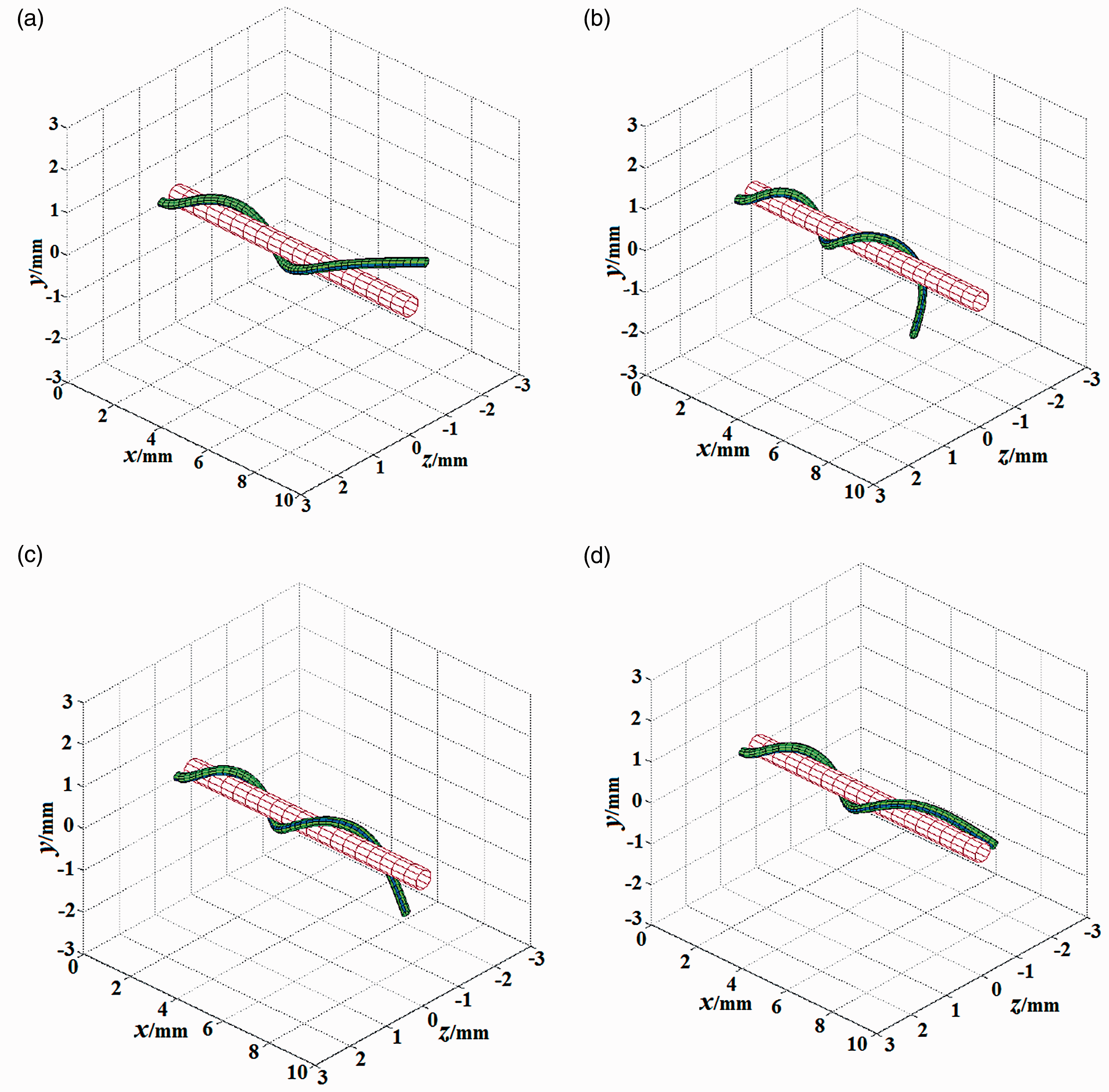
Experimental verification
Because of the narrow, closed and invisible twisting chamber, the actual movement of the fiber cannot be observed by the imaging device. The movement law of the free-end fiber is consistent with the space distribution and morphological conformation of the flexible fiber in the yarn. Therefore, the research on the motion characteristics of the free-end fiber in the twisting chamber could be transformed into the research on the space distribution and morphological conformation of the flexible fiber in the yarn structure.
Experimental parameters
Spinning process parameters

Yarn appearance structure
The specimen was tested using a Digital Microscope KH-7700, according to GB/T398-2008.
23
Select a certain length of the sample yarn and fix its two ends on the observing glass, keeping the original shape without being changed by the external forces. Place the sample yarn under the hi-scope microscope. The magnification of the yarns is 160 times. The main appearance morphological characteristics of yarns a, b, and c are shown in Figure 8. The twist angle θ is the angle between the yarn axis and the fiber axis on the yarn surface.
Yarn appearance structure. (a) Appearance structure of a yarn. (b) Appearance structure of b yarn. (c) Appearance structure of c yarn.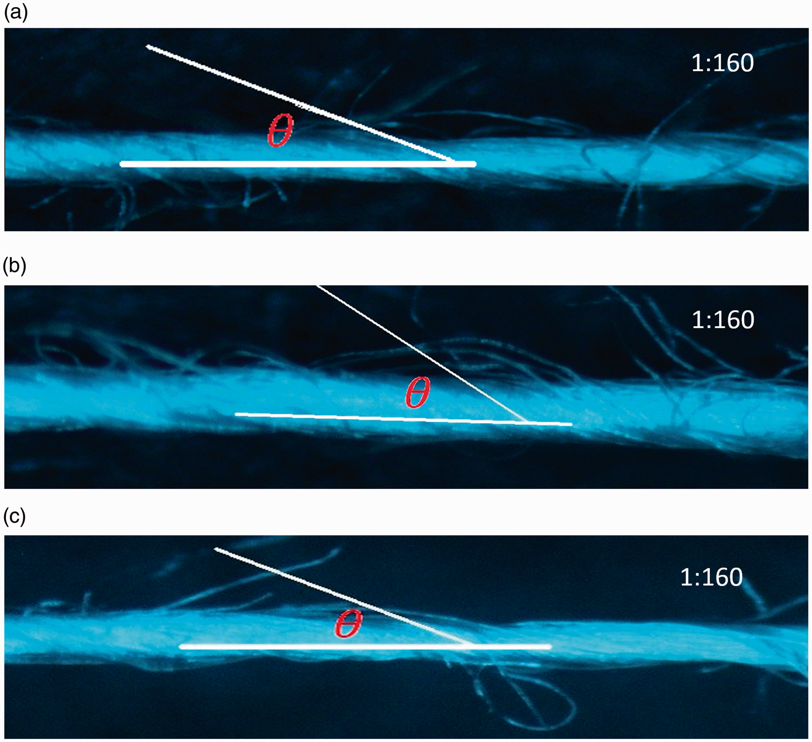
Comparing the yarn appearance structure of a and b, the twist angle θ of b yarn is larger than that of a yarn, which is better for the yarn tensile properties. The yarns a and b use the same raw material of viscose fiber n which has the same count and bending stiffness. The yarn b under the nozzle pressure of 0.55 MPa received a larger airflow force on the free-end fiber, which generates a larger fiber bending deformation. Comparing the yarn appearance structure of b and c, the twist angle θ of b yarn is larger than that of c yarn. The yarn b uses the raw material of viscose fiber n which has the same bending stiffness, but larger count than the viscose fiber k. Under the same nozzle pressure of 0.55 MPa which generates the same airflow force on the free-end fiber, the yarn b will get a larger fiber bending deformation.
Yarn cross-section structure
The specimen was tested using a Digital Microscope KH-7700, according to GB/T5324-2009.
24
Hardy’s thin cross-sections were used to analyze the cross-section characteristic parameters of yarn d. Take a bundle of wool fibers and straighten them by hand. Wrap a piece of yarn d in the wool and place it in the groove of the Hardy’s slicer. Use a sharp single-sided blade to cut the fibers exposed on the front and back of the Hardy’s slicer. Turn the screw back in place. Rotate the precision screw half or one grid so that the fiber bundle slightly protrudes from the surface of the metal plate and is then exposed. The fibers are coated with a thin layer of collodion. After the collodion is dry, it is sliced at an angle of about 10° along the metal plate surface with a sharp single-sided blade. Place the sample under the hi-scope microscope. The magnification is 800 times. The main cross-section appearance morphological characteristics of the yarn d are shown in Figure 9. According to the microscope image of the cross-section of the yarn, the yarn center is selected and the circular outline of the yarn is drawn. Then, the radius of the yarn circular outline is divided into five equal parts and four concentric circles are drawn. In order to make the test result more accurate, each yarn sample is cut into 20 slices.
Cross-section structure of d yarn.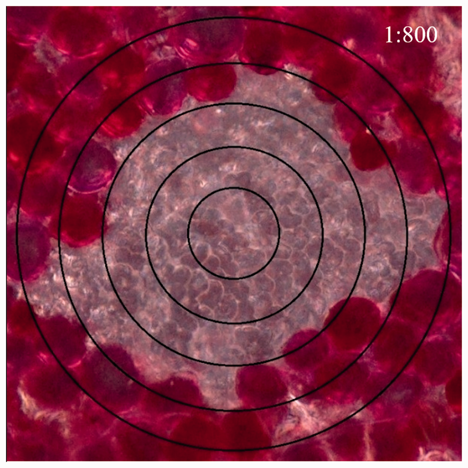
The number of fiber components in each concentric circle is counted, and the average value is taken as the frequency distribution of the fibers in each layer. When counting the number of fiber components in each layer of the concentric circle, take the one-half of the fiber cross-section as the boundary. If the fiber cross-section is greater than one-half, it is counted as 1. If the fiber cross-section is smaller than one-half, it is counted as 0. If each adjacent concentric circle contains one-half of the fiber cross-section, then the number of fibers per layer is plus 1. Comparing the Hamilton Transfer Index of viscose fiber n and cotton fiber in the cross-section structure of d yarn, the cotton fiber cross-section is waist round in Figure 9. The numberof fibre components for viscose fiber n in cross-section is evaluated as 55. The number for cotton fiber in cross-section is evaluated as 63. The cross-section of viscose fiber n is different from the cotton fiber, so the packing density of fibers in yarn cross-section is the ratio of fibers cross-sectional area to yarn cross-sectional area. The packing density of viscose fiber n in cross-section is 46%. The packing density of cotton fiber in cross-section is 54%. The Hamilton index of viscose fiber n in cross-section is 1.8%. The Hamilton index of cotton fiber in cross-section is −1.1%. The cotton fibers were distributed in the center of d yarn more and viscose fibers n were distributed around the cotton fibers. The number of cotton fibers is a little larger than the number of viscose fibers n. The cotton fiber has the same count with the viscose fiber n and the cotton fiber has a larger bending stiffness than the viscose fiber n. During the vortex spun yarn forming process, under the same nozzle pressure of 0.55 MPa which generates the same airflow force on the free-end fiber, the viscose fiber n will receive a larger fiber bending deformation and twist angle. Then the viscose fiber n tends to be distributed in the surface of d yarn and pulled out of d yarn. The cotton fiber tends to distribute in the center of d yarn.
Conclusions
This paper studied the fiber movement in vortex spinning based on the flexible fiber finite element model, according to the theoretical mechanical analysis of the vortex spun yarn forming process. The finite element simulation and analysis of the different trajectories of free-end fiber in vortex spinning under different process parameters were carried out. The influence of the fiber count, fiber bending stiffness and nozzle pressure on the fiber transfer and distribution was analyzed and verified by experiments of tracer fiber and yarn slicing. The numerical simulation and the experiments’ results show a consistent correlation of different process parameters and fiber movement, such as the fiber count increasing, the fiber bending stiffness increasing, or the nozzle pressure decreasing, and the fiber tending to get a smaller twist angle and becoming more easily distributed in the center of the yarn. So, this paper provides a theoretical basis for the study of free-end fiber trajectory in vortex spinning under different process parameters. It provides a guide to the structure design of vortex spun yarn and the production practice of vortex spinning.
Footnotes
Declaration of conflicting interests
The authors declared no potential conflicts of interest with respect to the research, authorship, and/or publication of this article.
Funding
The authors disclosed receipt of the following financial support for the research, authorship, and/or publication of this article: This work was supported by the National Key R&D Program of China (2017YFB0309200), Fundamental Research Funds for the Central Universities (JUSRP11801), Top-notch Academic Programs Project of Jiangsu Higher Education Institutions (PPZY2015B147) and Priority Academic Program Development of Jiangsu Higher Education Institutions (37[2014] issued by General Office of the People’s Government of Jiangsu Provence).