




Abstract
Although extensive focus has been placed on the ballistic performance of projectiles with certain macroscale geometries and dimensions, the microscale geometries are not as rigorously standardized. The localized stress concentrations arising from microscale geometries introduce multiaxial and locally concentrated stress states within the constituent material of the soft-armor target, which can result in premature failure that is not predicted with existing models. In this study, the microscale edge/corner geometries of right circular cylinder (RCC) projectiles are varied, and their respective ballistic performance was determined via experiments to examine the effects of the localized stress concentrations. Target panels were examined post-mortem and the effects of these localized stress concentrations on the failure modes were quantified. Experiments results indicate that stress concentrations drastically reduce the ballistic performance of the soft armor targets, and the fabric targets appear to fail without significant strain energy absorption.
The significance and importance of soft body armors for personnel protection has increased multiple-fold over the decades since their first conception. The impact- and energy-absorption mechanisms during the ballistic penetration of soft-armor systems have long been a subject of extensive studies. The exact underlying physics behind the impact and failure phenomena are still not fully understood, and still largely depend on empirical data from extensive ballistic tests. In typical analyses of soft-armor ballistic performance, several types of projectiles are used, namely spheres, right circular cylinders (RCCs), and fragment-simulating projectiles (FSPs). RCCs have proven to be a popular choice for projectile geometry because of their relative ease of machining, testing, analysis, and modeling. For these reasons, existing literature investigating the ballistic performance of soft-armor targets under RCC impact are too numerous to count.
In order to standardize the method of obtaining a ballistic limit velocity, design guidelines such as the MIL-DTL-46593B detail exact dimensions and tolerances of FSPs required for testing soft-armor targets.
1
However, the microscale dimensions have not been as rigorously specified for other types of projectiles. Cunniff examined the effects of variations in RCC projectile physical properties and dimension tolerances,
2
but did not look further into the effects of edge sharpness on the ballistic performance. The importance of these microscale dimensions should not be understated, as one would typically expect a target material to fail more easily when impacted by a sharper edge geometry than a blunt edge geometry. In fact, Hertzian contact analysis of a cylindrical punch on a plane shows that an idealized sharp corner results in a contact stress that is theoretically infinite at the boundary of the impact face, as in Figure 1.
Pressure profile p(x) and indentation displacement profile u
z
(x) of an elastic half-space indenter by a planar punch of width 2b.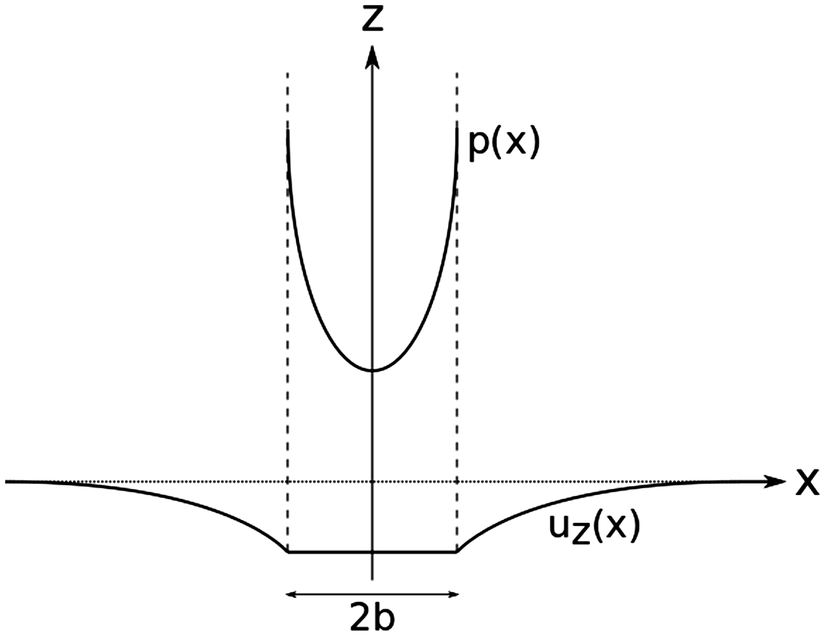
A similar Hertzian pressure analysis was performed by Attwood et al. for a cubical punch on an ultra-high molecular weight polyethylene composite beam to give an idea of the stress states beneath the contact zone.
3
For a flat 2D planar punch indenting an elastic half-space,

The localized stress concentrations due to microscale geometries have been previously shown to reduce the effectiveness of polymer fibers by introducing off-axis stresses that result in premature fiber failure. Mayo and Wetzel demonstrated that by indenting certain polymer fibers with a razor blade, the fiber consequently fails in a transverse shear-like cutting manner, which drastically reduces the effective failure strain as stresses are concentrated at the blade tip. 4 Hudspeth et al. took it a step further and showed that the failure modes transition from fibrillation under pure axial tension when using large, round indenters to a more shear-like cutting mode similar to the results of Mayo and Wetzel when using razor blades.5,6 Interestingly, the failure modes of a polymer fiber using an FSP indenter transitions from axial tensile failure at low subtended angles of the fiber to an off-axis cutting-mode failure that occurs near the edges of the FSP face. These exact same result and findings were further simulated by Sockalingam et al. to show the effects of multiaxial stress states numerically. 7
Hudspeth et al. later transversely impacted high-performance polymer yarns with the same round, FSP, and razor blade projectiles in order to demonstrate the same detrimental effects of localized stress concentrations. 8 In the same manner as the fibers under quasistatic indentation, the razor blade projectiles initiated stress states that reduced the overall ballistic performance of the yarn compared to a round indenter, which tends to initiate axial tensile failure in the yarns. These same stress concentrations are undoubtedly introduced in a similar manner during projectile impact on a soft-armor target, which may result in similar premature failure response.
In this study, the effects of localized stress concentrations that occur at the corners of projectiles are analyzed with respect to their influence on ballistic performance using both experimental and analytical methods, with a focus on RCC projectiles. Experimentally, high-rigidity projectiles with different corner radii of curvature were used to impact a Twaron® soft-armor fabric panel, and the ballistic performance was then determined to compare the effects of these localized stress concentrations. Post-mortem analysis was performed to examine the difference and progression of failure modes in the through-thickness direction when RCCs of different edge radii are used to impact these panels.
Experimental procedure
Gas gun setup
Projectiles were shot with a single-stage smooth-bore light-gas gun with an inner bore diameter of 9.80 mm and barrel length of 3.66 m. In order to improve accuracy and reduce trajectory instability due to drag on the RCC projectiles, the target was located approximately 0.4 m from the tip of the barrel. Alignment was performed to ensure perpendicularity of the target panel to the shot axis. A steel safety chamber was placed behind the target panel mount to retrieve any exiting projectiles using either terry cloth rags or 10% by weight porcine skin ballistic gelatin (ambient temperatures permitting).
Target panels were clamped on all four corners using L-brackets with inner neoprene rubber linings (50A durometer) of 25.4 mm (1 inch) width to grip the target panel firmly, leaving an exposed surface area of 0.254 × 0.254 m2 (10 × 10 inches). The L-brackets were secured using 12 flanged screws equally spaced on all corners, and then tightened using a torque wrench to a maximum torque of 2.8 N-m (25 in-lb). Velocity measurements were made using in-house laser diode instrumentation to measure velocities accurate to within 3.05 m/s (10 ft/s).
Target material
The base Twaron® balanced plain-weave fabric samples (840 denier yarns, 27 × 27 ends/picks per inch) were obtained from Barrday (Charlotte, North Carolina, USA) and manufactured in 2015, with an areal density of 0.215 kg/m2 (0.044 lb/ft2) per ply, 3.011 kg/m2 (0.617 lb/ft2) for 14 plies, and 4.732 kg/m2 (0.969 lb/ft2) for 22 plies. The number of plies was chosen in order to calibrate the ballistic test results with those provided by the manufacturer and with a previous study performed by the authors. 9 Fabric materials were cut to sample sizes of 0.305 × 0.305 m2 (12 × 12 inches), and subsequently edge-stitched three times together with a 25.4 mm (1 inch) margin from the edges for easier handling. The edge-stitching does not significantly alter the ballistic performance. Panels were kept in storage in an air-tight container with clay desiccant packets for at least 24 h prior to shooting to absorb any moisture that may be present due to transportation.
Projectile material and geometries
Steel RCCs were cut and faced out of 7 mm rod stock, with diameters and lengths measured to be within 7.00 ± 0.02 mm. In accordance with MIL-DTL-46593B,
1
the projectiles were verified to have hardnesses of at least Rc 31 ± 1 using a spot hardness tester. Edge geometries were varied to different radii of curvature. Sharpened corners were achieved by cutting and facing, while blunt corners were obtained by edge filleting after cutting and facing. To achieve somewhat intermediate radii of curvature, a batch of projectiles was tumbled with suitable ceramic media for 5 h. Projectile edge geometries were measured using scanning electron microscopy (Nova NanoSEM 200 (Thermo Fisher Scientific, USA)). Typical radii of curvature were approximately 120–150 µm for the blunt projectiles, 100–120 µm for the tumbled projectiles, and 35–75 µm for the sharpened projectiles, as shown in the micrograph in Figure 2 (Figure 2 shows diameters rather than radii of curvature due to the microscope software). It should be noted that exact radii of curvature are difficult to achieve at the microscale when machining macroscale dimensions, but the different processes nonetheless provide three relatively distinct regimes of edge radii, as per Table 1. As a comparison, 7 mm spheres were also tested; these represent the extreme case of projectile “bluntness.” The parameter η in Table 1 refers to the areal density ratio of the target to the projectile.
Micrographs of typical RCC projectiles prior to shooting with (a, b) sharp corners, (c) tumbled corners, and (d) blunted corners. Projectile and target materials with respective properties RCC, right circular cylinder.

Shooting procedure
A total of 12 shots per panel were performed to determine the ballistic limit using the bracketing method as detailed in NIJ-0101.06. 10 Shot locations were predetermined and marked using a template such that the shots were located 25.4 mm (1 inch) from the panel stitching, at least 50.8 mm (2 inches) apart from each other, and (as much as possible) that the principal yarns do not overlap. For uniformity in testing, pre-and post-test temperatures and humidity levels were also recorded to ensure that testing conditions did not vary significantly.
As the test chamber and targets are not exactly the same as those detailed in the NIJ-0101.06 standard, 10 the methodology was slightly modified. The first shot was fired at a desired velocity of 304.8 m/s (1000 ft/s); this velocity was referenced and estimated with respect to the manufacturer's datasheet for a 9 mm FMJ (full metal jacket) projectile impact. If the shot outcome was a partial penetration, a shot outcome of “0” was assigned to the shot number and the subsequent desired shot velocity was increased by 30.5 m/s (100 ft/s); if the shot outcome was a complete penetration, a shot outcome of “1” was assigned to the shot number and the subsequent desired shot velocity is decreased by 304.8 m/s (1000 ft/s). In the case of an unacceptable shot, for example inaccurate shot location or large deviation of actual striking velocity from desired shot velocity of more than 3.05 m/s (10 ft/s), the shot was repeated.
The process was repeated till the first shot outcome “reversal,” that is from partial to complete penetration or vice-versa. At this point, the change in desired velocity was lowered to 22.9 m/s (75 ft/s). Similarly, if the shot outcome was a partial penetration, a shot outcome of “0” was assigned to the shot number and the subsequent desired shot velocity was increased by 22.9 m/s (75 ft/s); if the shot outcome was a complete penetration, a shot outcome of “1” was assigned to the shot number and the subsequent desired shot velocity was decreased by 22.9 m/s (75 ft/s).
This process was repeated till the next shot outcome “reversal,” where the desired velocity step was further lowered to 15.2 m/s (50 ft/s). If the shot outcome was a partial penetration, a shot outcome of “0” was assigned to the shot number and the subsequent desired shot velocity was increased by 15.2 m/s (50 ft/s); if the shot outcome was a complete penetration, a shot outcome of “1” was assigned to the shot number and the subsequent desired shot velocity was decreased by 15.2 m/s (50 ft/s). The procedure was then repeated till a total of 12 acceptable shots were completed, up to a total of 16 possible shots per target panel if necessary in the case of unacceptable shots.
Results and discussion
Recorded pre- and post-testing temperatures and relative humidity levels were 17.0–26.0 ℃ and 34–49%, respectively. Tests were completed within 5 h of test commencement.
Ballistic limit results
Results of ballistic limit tests

RCC, right circular cylinder.
Maximum possible velocities of 462.0 m/s were achieved with the gun without sufficient complete penetration results, and the ballistic limit is assumed to be at or above this velocity.
The kinetic energy absorbed at the ballistic limit KEabs was observed to decrease with the corner radius Rc, which is expected. These results were fitted with a power-law fit to approximate the relationship (Figure 3).
Plot of kinetic energy absorption at V50 ballistic limit for 22- and 14-ply Twaron® panels, along with power-law curve-fits.
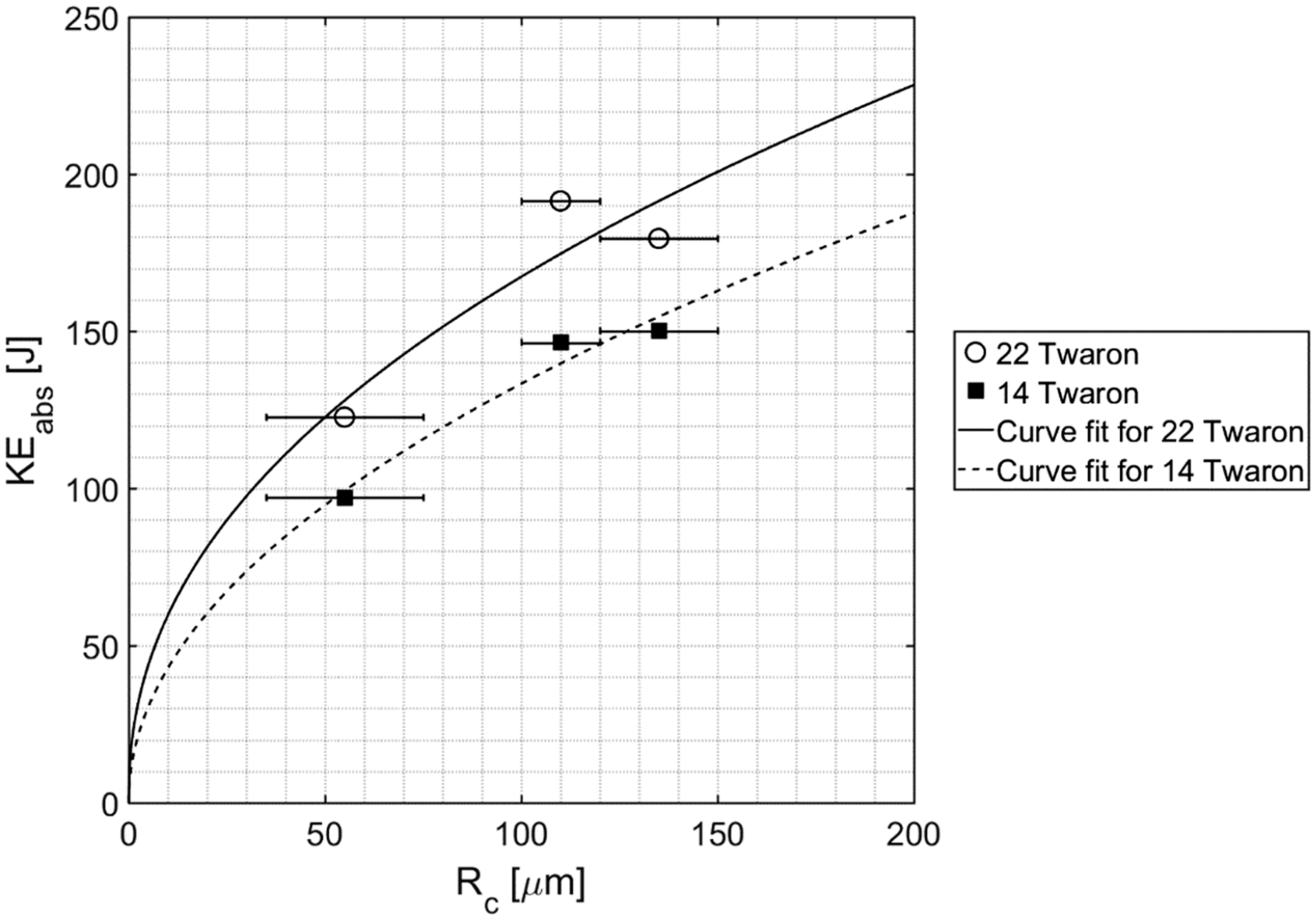
The fits in equation 3 did not include the V50 kinetic energy absorbed for the spherical projectile, since an actual V50 was not determined. The exponents of both are very close to a value of 0.5, so the data points were forced to a square root function fit for a simpler approximation without significant decrease in the corresponding R2 values.
Target post-mortem analysis
Post-mortem analysis was performed on the individual impacted fabric plies to investigate the effects of edge sharpness of the failure modes of these plies during impact. Visual inspection of the target plies was performed and the failure mode of each shot location through the plies was categorized into three main types of failure using the same methodology detailed in a previous work:
12
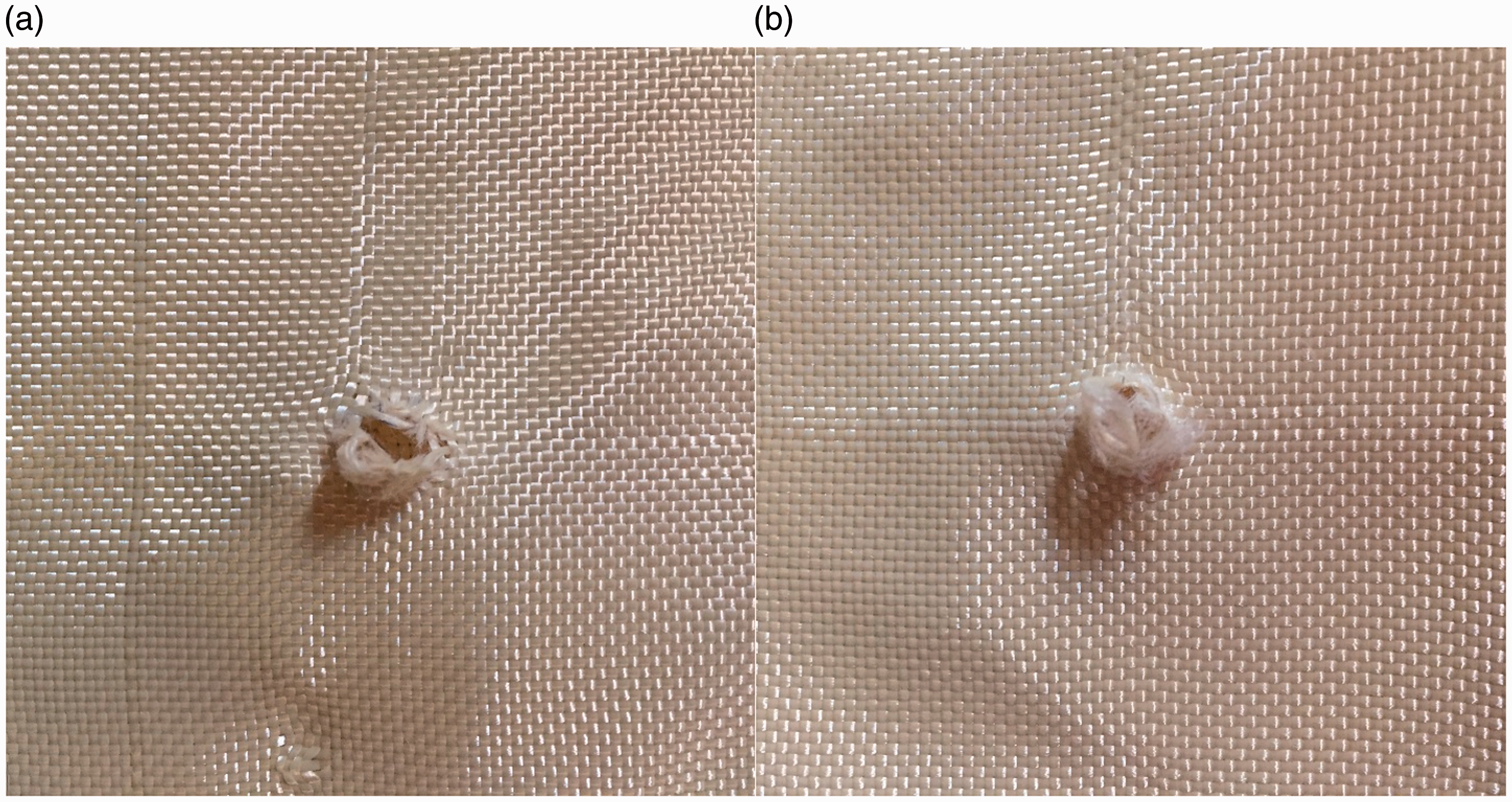
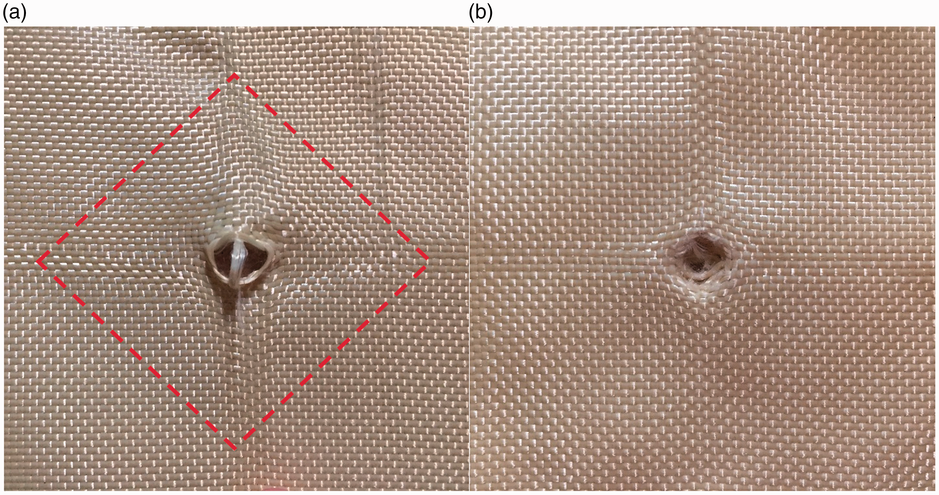
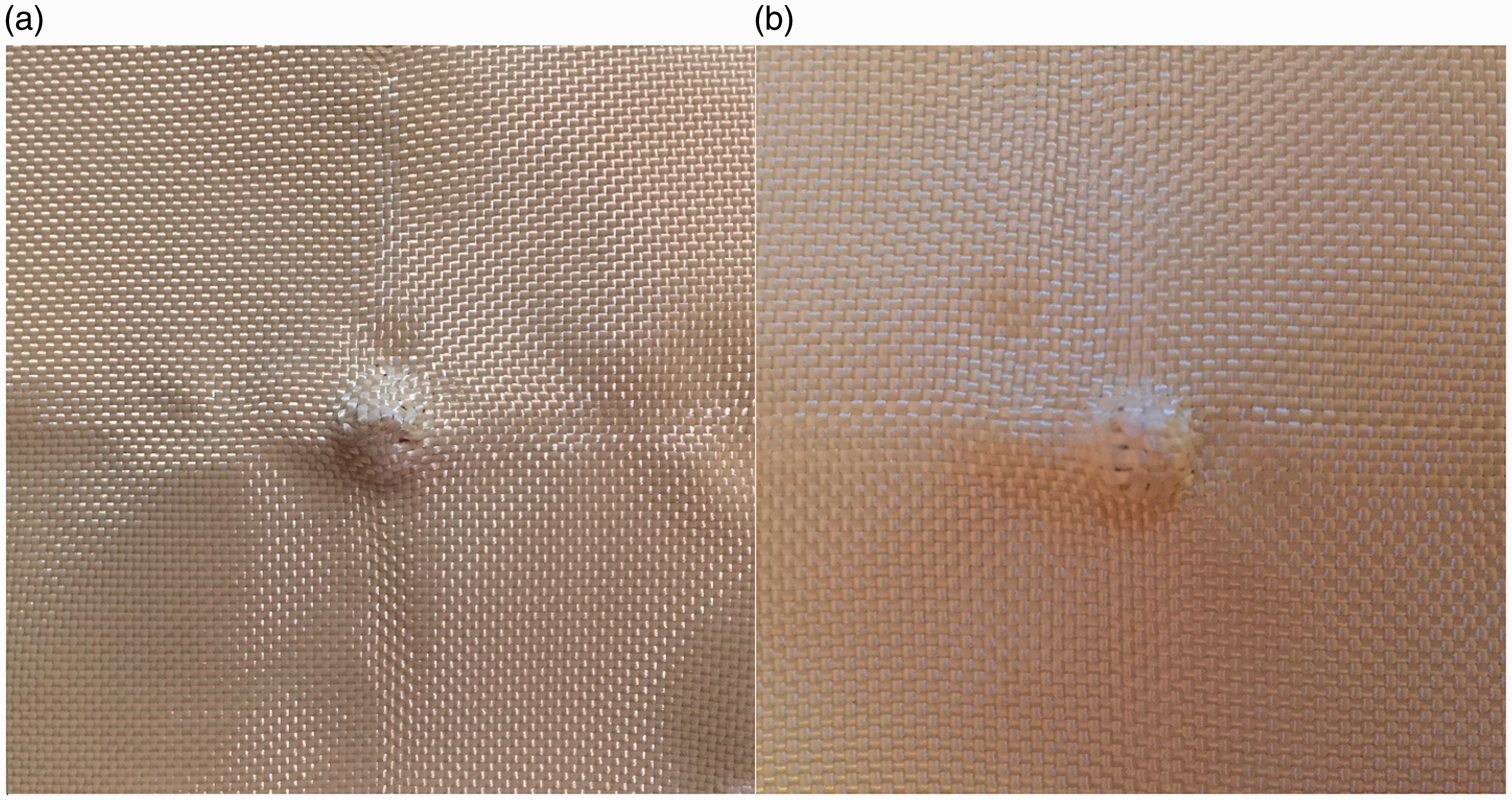
Rupture. In this mode, the edges of the shot hole appear to be punched out and fail in a very localized manner. The hole is often large and clean, with minimal transverse fabric movement around the shot location (Figure 4). Yarn rupture modes typically occur at the strike face of the target panel. Mixed mode. Once the projectile has ruptured the first few layers, the subsequent layers may either show ply damage via yarn pull-out (Figure 5(a)) or via nosing-through as the yarns slide around the projectile (Figure 5(b)). These defeat mechanisms are collectively termed “mixed mode” as the differences between them may be hard to distinguish, since these modes typically occur in the middle to end plies. In mixed mode failure, broken yarns may be observed, though not as frequently as in rupture mode. Principal yarn translation and the characteristic tetrahedral transverse wavefront of fabric plies are more prominent. Intact. At low velocities, the projectile does not fully penetrate the target panel, occasionally resulting in layers that show slight indentation and minimal yarn pull-out but exhibit no means of projectile perforation (Figure 6). Since the focus is on the defeat mechanisms and failure modes of the fabric plies, we consider this form of response to be “intact,” even though the fabric ply shows obvious signs of being impacted. Post-mortem images showing (a) front side of shot exhibiting localized yarn rupture, and (b) rear side of shot exhibiting severe yarn rupture and entanglement. Post-mortem images showing (a) rear side of shot exhibiting significant yarn pull-out with principal yarn translation, and (b) front side of shot exhibiting nosing-through of projectile. Red dashed parallelogram highlights evidence of transverse wavefront propagation. Post-mortem image showing indentation imprint by (a) an RCC, and (b) a sphere. Both exhibit yarn translation at the impact site but no signs of projectile perforation.
Since the visual inspection method is highly qualitative, the results and observations gleaned from the post-mortem data merely present a trend study for comparison. For each target panel, the total number of rupture/mixed mode/intact layers were first determined and then calculated as a percentage of the number of shots multiplied by the number of layers. These results are given in Table 3. Rupture modes observed at shot locations of the steel spheres exhibited severe damage at a small point of contact at the tip of the sphere, and while the yarns are indeed ruptured, they should not be considered the same form of rupture mode as induced by an RCC, since the yarns impacted by a sphere can rupture without significant aperture formation for the steel sphere to perforate. Nonetheless, the steel sphere results are included as a reference. The data from Table 3 are plotted in Figure 7 for a more visual comparison.
Stacked bar graph of different failure modes and percentage occurrence per target panel, along with KEabs kinetic energy absorption trend. Results of post-mortem analysis on target panels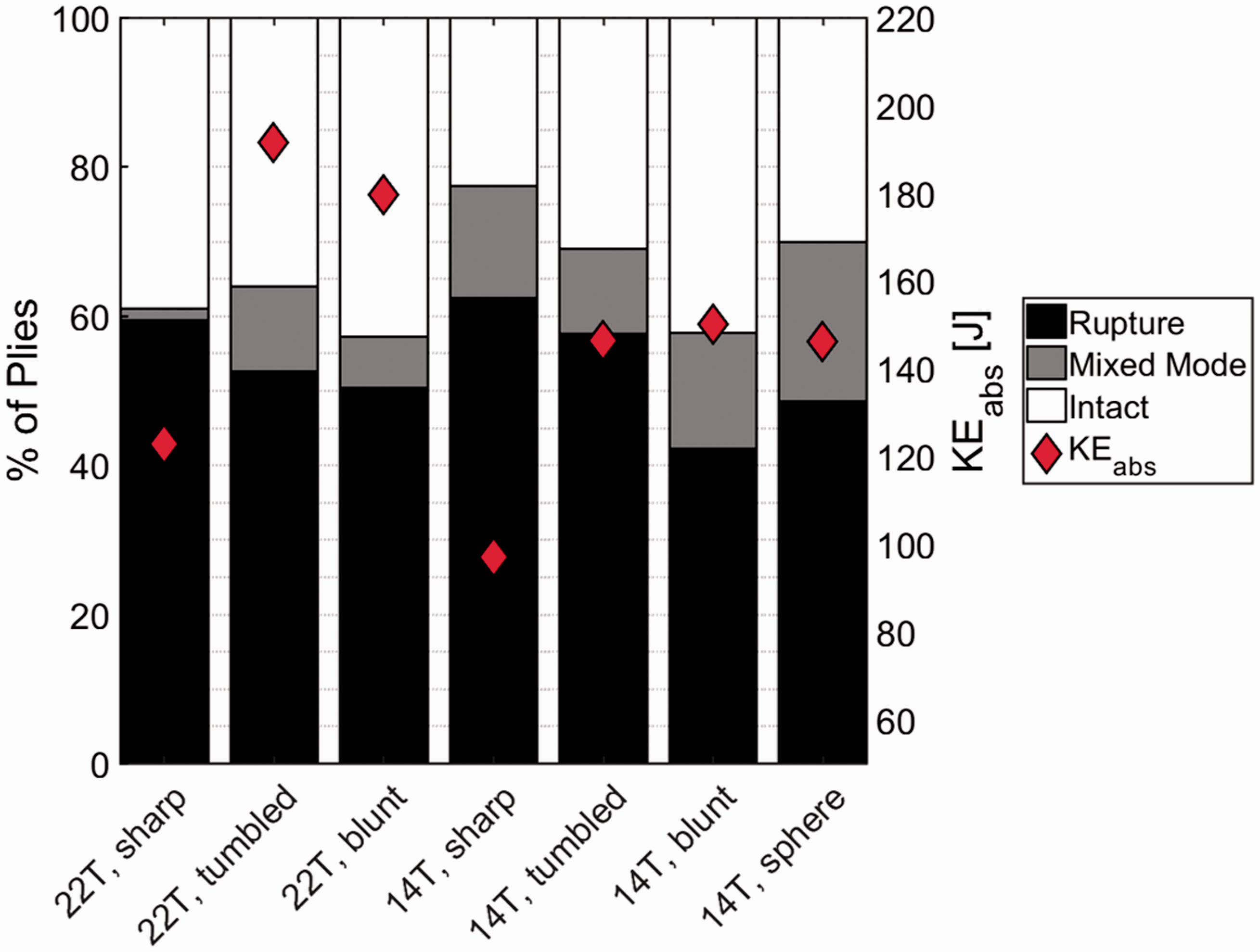
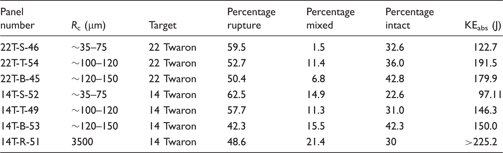
It should be noted that the velocities impacting the target panels for each shot are different as per the 12-shot method detailed previously. However, these percentage occurrences reflect the distribution of failure modes at or near the V50 ballistic limit. The sharp-edged projectiles tend to result in a higher percentage of rupture modes at the strike face and the lowest percentage of intact plies at the rear face of the target panel. On the other hand, blunt projectiles result in the lowest percentage of rupture modes and highest percentage of rear-face intact plies. A general trend may be noted in which a larger degree of rupturing results in lower energy absorption. This trend is also more distinct for the thinner 14-ply target panels compared to the 22-ply target panels, where the rupturing mechanism may not persist far enough in the through-thickness direction during perforation (at least when impacted at the ballistic limit velocity). These results further support the hypothesis that off-axis stress states within the constituent polymer fiber material tend to result in premature failure.
Projectile post-mortem analysis
Post-impact projectile diameters and lengths were also measured to quantify the amount of deformation or damage occurring to the projectiles during impact. Post-impact projectiles were caught with a catch chamber lined with cotton jersey cloth rags and soft rubber sheets to prevent deformation of the perforated projectiles upon impact with the chamber walls. On occasion, partially penetrated projectiles were trapped within the fabric target layers, and subsequent shots may impact these trapped projectiles, resulting in extreme deformation. These projectiles were not considered for post-mortem analysis. For all projectiles, the post-impact diameters and lengths were 7.01 ± 0.005 mm and 7.01 ± 0.016 mm respectively, indicating no statistically significant macroscale deformation. Larger deviations in post-impact lengths were most likely due to residue from impact at the strike face, which was not removed to preserve the condition of the projectiles as-retrieved. A closer inspection of these projectiles using scanning electron microscopy revealed that projectile damage tends to occur at the edges of the RCCs (Figure 8). The degree of deformation appears to be somewhat related to the impact velocity and the outcome of the shot (i.e., partial or complete penetration). However, completely penetrated projectiles were not examined as the method of projectile retrieval behind the target may have resulted in further deformation.
Microscale projectile mushrooming deformation can be observed at the RCC edges.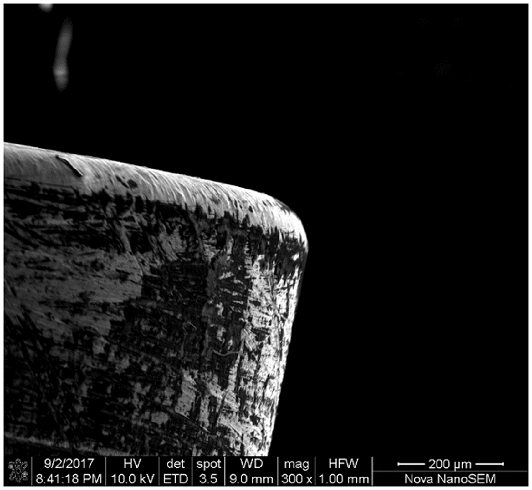
In Figure 9, partially penetrated projectiles for blunt- and sharp-edged RCCs were examined to see if the edge radius of curvature changed significantly. In Figure 9(a), the blunt-edged RCC exhibited moderate localized damage after penetrating 20 layers (17 rupture, 3 mixed-mode, 2 intact). In Figure 9(b), the sharp-edged RCC, on the other hand, showed some degree of projectile edge blunting after penetrating 18 layers (18 rupture, 0 mixed-mode, 4 intact). It may be possible that the larger stress concentrations result in a much more premature failure of the material directly in front of the projectile, resulting in less microscale damage. These results warrant further investigation into the microscale damage to the projectile as a means of improving ballistic performance.
Micrographs of (a) blunt RCC edge for 22T-B-45 projectile shot at velocity of 340 m/s, and (b) sharp RCC edge for 22T-S-46 projectile shot at velocity of 296.3 m/s. Both striking velocities were sub-ballistic limit and resulted in partially penetrated projectiles.
Conclusions
The microscale stress concentrations occurring at the edges of projectiles were examined for their effects on the ballistic performance on soft-armor targets. Steel RCCs of various edge radii of curvature and spherical projectiles were used to impact Twaron® panels to obtain the ballistic limit. Sharper edges were shown to initiate more off-axis stress states in the constituent fiber material, resulting in premature failure, as is expected of sharper geometry. Post-mortem analysis of the panels revealed that three main regimes of target material response were observed, namely via yarn rupture, mixed mode defeat via yarn pull-out or windowing, and exhibiting no projectile perforation. Sharper edge radii of the RCC projectiles were shown to result in more yarn rupture due to off-axis stress states. Results of this study indicate that multiaxial stress states and stress concentrations also result in reduced performance of the fabric armor target panels. In view of this, care should be taken in ensuring that physical dimensions and tolerances of RCC projectiles are rigorously defined as they are for FSP dimensions.
Footnotes
Acknowledgements
The authors would like to thank the U.S. Army, P.M. Soldier Protection and Individual Equipment, Technical Management Directorate for their support. The authors would also like to thank Stephanie Martinez-Morales for her help and contribution with the arduous task of fabric panel stitching, ballistic testing of the fabric panels, post-mortem analysis, and electron microscopy.
Declaration of conflicting interests
The authors declared no potential conflicts of interest with respect to the research, authorship, and/or publication of this article.
Funding
The authors received no financial support for the research, authorship, and/or publication of this article.