
Abstract
As wearable electronics become more prevalent in everyday life, there is a growing desire to integrate circuits and antennae into clothing. One way that this integration may occur is through use of electronic textiles (e-textiles). However, changes in environmental and wear conditions may affect the conductive data communication performance of the e-textile, such as surface resistivity and antenna radiation characteristics. In this study, the effects of pilling, wrinkling, abrasion, and laundering of e-textiles were examined for resistivity performance. E-textile resistivity performance from both direct current (DC) and radiofrequency (RF) perspectives were measured following AATCC and ASTM standards. For DC performance, results indicate that pilling causes severe damage to e-textile resistivity, while laundering and wrinkling did not substantially affect e-textile resistivity performance. For RF performance in this study, an e-textile microstrip patch antenna was designed and data were collected under similar environmental and wear conditions. RF performance change corresponds with DC performance change. The findings of this paper highlight limitations of the evaluated e-textile performance, and provide new perspectives regarding improvements to e-textile fabrication for sustaining performance through environmental and wear operations.
Wireless body area networks (WBANs) have been a trending topic in recent years because of their applications in military, sports, and wellness industries. WBANs (also known as “wearables”) refer to a technology that uses a combination of wearable sensors, wireless communication, and data analysis to provide consumers with detailed information about physiological conditions. For example, Apple watch and Fitbit wearables can continuously monitor the wearer’s heart rate, distance/steps per day, and sleep patterns via wrist-device application. It is estimated that the wearables market will grow into a US$34.2 billion industry and production will increase from $123 million to $411 million by the year 2020. One particular challenge when deploying a WBAN sensor is to design and implement a wearable antenna. In general, wearable antenna designs need to be low profile, lightweight, small volume, low production cost, and they need to exhibit minimum performance degradation in terms of input impedance matching, bandwidth, and efficiency. Electronic-textile (e-textile) antennae and circuits show great potential to implement WBANs due to low mass, physical flexibility, and ease of integration into the garment structure.1–4
Many different techniques and substrate materials have been used to develop communicative textiles. One common approach is the embroidery of metal-coated conductive threads on readily-available, ordinary textiles (e.g., medium weight 100% cotton twill denim fabric).5,6However, some of the metal-coated conductive threads are simply too fragile (leading to thread breakage) for use in standard embroidery machines. E-textiles can also be constructed by depositing a conductive metal layer on top of a fabric substrate via conductive ink printing or metal coating.7,8These “applied” e-textile approaches can provide excellent isotropic resistivity and a thin profile, but it is necessary to understand how changes in the environment or wear conditions affect e-textile performance for antenna application.
In the past decade a number of studies have focused on how e-textile antenna performance varies under environmental changes. Annelien et al. found that increasing the moisture content of a textile antenna could increase the permittivity and loss tangent of the material; 9 thus it could change the antenna resonance frequency and decrease antenna efficiency. Studies involving the antenna bending effect demonstrated that antenna bending could broaden the radiation pattern along the bending plane and change the impedance matching.10,11Wearable antenna performance was tested in a freezing environment and it was found that ice significantly changed antenna impedance matching. 12 Qiang and Richard studied shape distortion on textile antenna performance and found that distortion can substantially degrade antenna radiation performance and shift resonance frequency. 13 Tero et al. investigated antenna performance under different moisture and low temperature conditions. 14 Loss et al. studied the influence of structural parameters on dielectric behavior of materials for textile antennas. 15 Castano and Flatau identified fabric structure platform influences, such as permanent deformation under harsh condition stressors like folding or bending, abrasion resistance, and compressibility (i.e., durability tests), and declared that performance under durability wear conditions must be taken into account when selecting e-textiles as smart fabric sensors or smart fabric transducers. 16
Previous research lacks comprehensive e-textile durability knowledge, based on AATCC and ASTM standards. Most studies to date have focused on e-textile performance at radio frequencies, but direct current (DC) characteristics, such as surface resistivity, remain to be explored. In this study, e-textile durability performance was measured under multiple conditions from both DC and radiofrequency (RF) perspectives. Two fabrics with metal coating technology were tested to identify and measure durability treatment influence on surface resistivity. Durability treatments (experimental factors) included moisture, perspiration, laundering, abrasion, pilling, wrinkling, and tensile or bursting strength tests. A wearable e-textile patch antenna was designed and constructed and subjected to similar durability tests. Lastly, the e-textile antenna was incorporated into a shirt worn on the human chest and performance changes were measured.
The next section describes the resistivity measurement protocol employed in this study and outlines influence of environmental and wear conditions on e-textile resistivity performance. Then a similar study was performed on an e-textile microstrip antenna and results are described. The final section summarizes research work, identifies study limitations, and highlights future directions for research in the area of e-textiles and antenna applications.
Durability tests of surface resistivities of two e-textiles
E-textiles
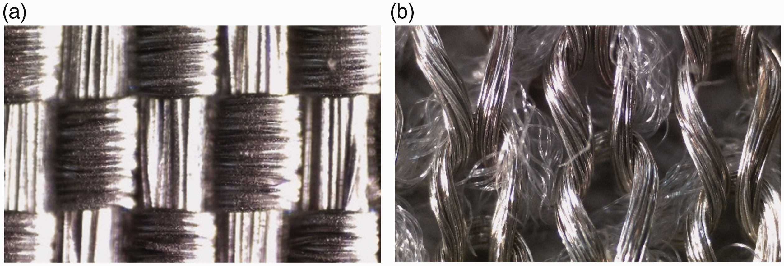
Two types of e-textiles were identified and selected for this study. One was a nickel–copper yarn-coated nylon ripstop (NC) (Figure 1(a)). The other e-textile was a jersey knit fabric with silver yarn-coated cotton/polyester (SJ) (Figure 1(b)). Both e-textiles were fabricated with coated yarns in the warp and filling/wales and course directions. Figure 2illustrates the structure of the two e-textiles via microscopic image. Images were photographed with a Fisher- brand intermediate digital compound microscope and motic imaging software. Note: all images use the above-mentioned equipment/software with a magnification level equal to 4. E-textiles used in this study are detailed along with methods and findings of the surface resistivity durability performance tests. Durability treatments included moisture, perspiration, laundering, abrasion, pilling, wrinkling, and tensile or bursting strength tests.
Photos of (a) NC fabric and (b) SJ fabric. Microscope images of (a) NC fabric and (b) SJ fabric.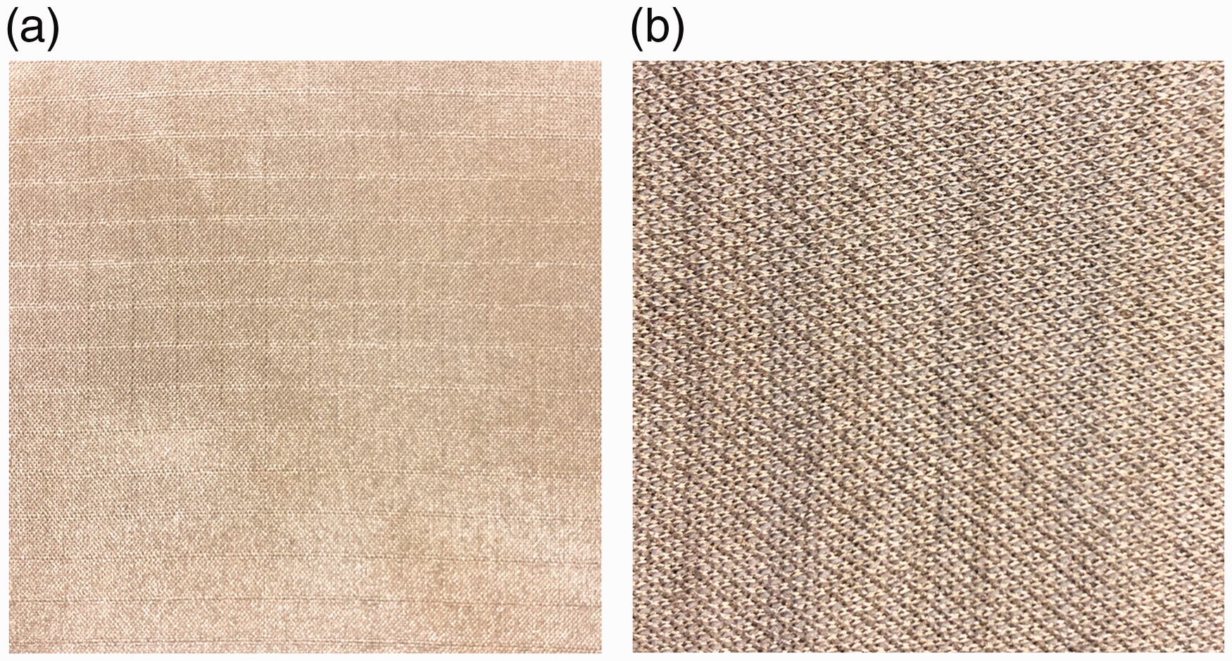
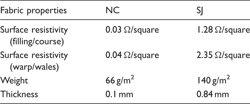
Material properties of NC and SJ fabrics
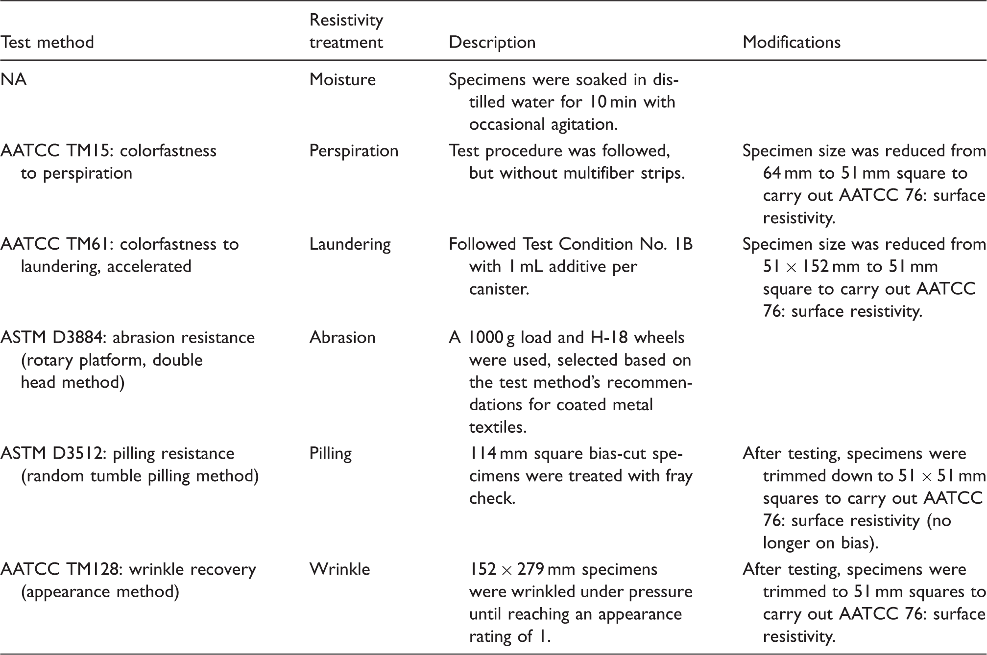
Durability test methods
Durability test results on e-textile surface resistivity
Based on the test methods outlined in Table 2, moisture, perspiration, laundering, taber abrasion, pilling, and wrinkle tests were performed on NC and SJ e-textiles to examine the effects of these durability tests on surface resistivity.
Moisture: water presence
Each specimen was saturated in a separate 500 mL beaker, filled with 250 mL distilled water, and occasionally agitated (stirred and tamped) with a glass stirring rod for 10 min. The specimen was removed from the water-filled beaker and placed flat on drying racks to air dry. Figure 3(a)and (b) illustrate the effect of moisture on the surface resistivity of the two fabrics. For the water-wet case, moisture does not change NC resistivity, but a decrease in resistivity value is observed in the SJ wales direction; for the water-dry case, the resistivities of both fabrics return to approximately their original values, with a slight increase in the wales direction.
The moisture effect on surface resistivity of (a) NC and (b) SJ.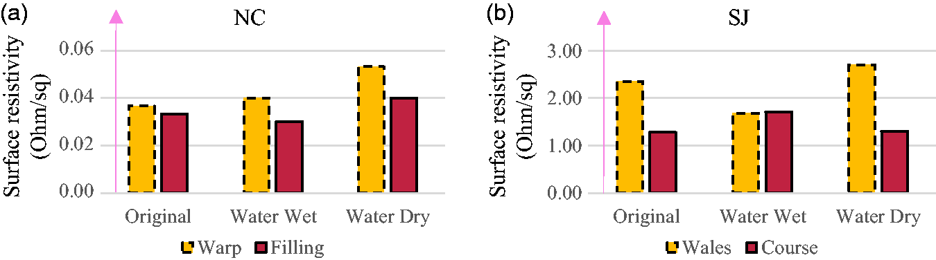
Perspiration
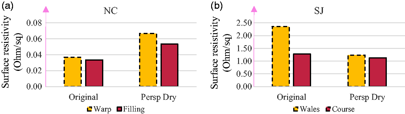
Effects of perspiration were tested using AATCC TM15. This test is originally designed to assess colorfastness to perspiration, but in this study the procedure was used to measure a change in surface resistivity when in the presence of perspiration. Effects of perspiration (residue) are visible via color change on both specimens, as illustrated in Figure 4. Figure 5outlines resistivity changes after the perspiration test. The resistivity of NC increased in both warp and filling directions, possibly due to the presence of the observed residue. The resistivity of SJ in both wales and course directions decreased, thus the perspiration solution appears to assist conduction in that yarn direction.
Photos of NC (a1) pre- and (a2) post-perspiration test and SJ (b1) pre- and (b2) post-perspiration test. The effect of perspiration on surface resistivity of (a) NC and (b) SJ.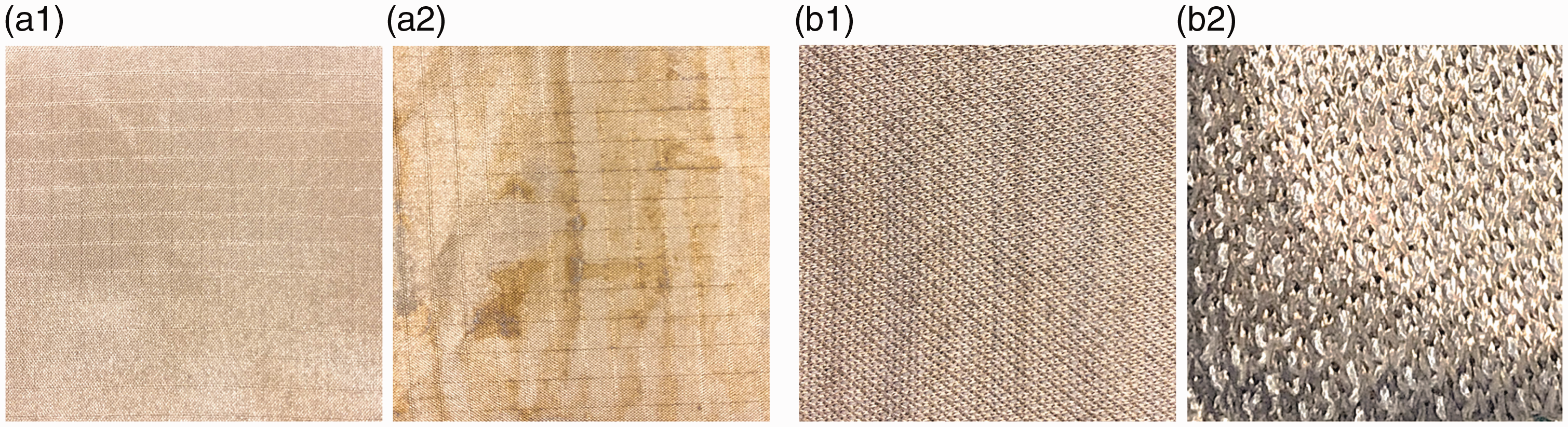
Laundering
Laundering procedure was based on AATCC TM61: Test Condition No. 1B, which simulates five home launderings in 20 min. This method is designed to test colorfastness to laundering, but the changes in surface resistivity were measured in this study. AATCC TM61 allows for testing of small specimens against a variety of home laundering products under standard and controlled conditions. Each laundering canister contained 10 rubber balls, one e-textile specimen, and a solution of 150 mL distilled water and 1 mL of additive. Additives were selected for testing to provide resistivity information on a scope of laundering products that may be used by an average consumer, along with recommended additives.
Additives included:
AATCC Standard reference high efficiency detergent (BLT); Seventh Generation Free & Clear plant-based detergent (BL); Texcare detergent (a factory recommended detergent for e-textiles) (BL); Downy Free & Clear fabric softener (BLB).
After laundering, specimens were trimmed to 51 mm square, rinsed with distilled water, and air-dried. Specimens were trimmed to accommodate textile edge fraying risk during the rotowash procedure.
Surface resistivity of NC slightly increased, particularly for standard detergent and softener (as shown in Figure 6(a)). This may have resulted from a loss of metal coating. Detergents and fabric softeners are known to leave residue on textiles, so it is possible that residual detergent and/or softener components masked effects of the e-textile metal coatings. The surface resistivity of SJ fabric in the wales direction decreased (Figure 6(b)), which may be due to observed shrinkage in that direction. Laundering did not affect the SJ resistivity in the course direction.
Laundry effect on surface resistivity of (a) NC and (b) SJ.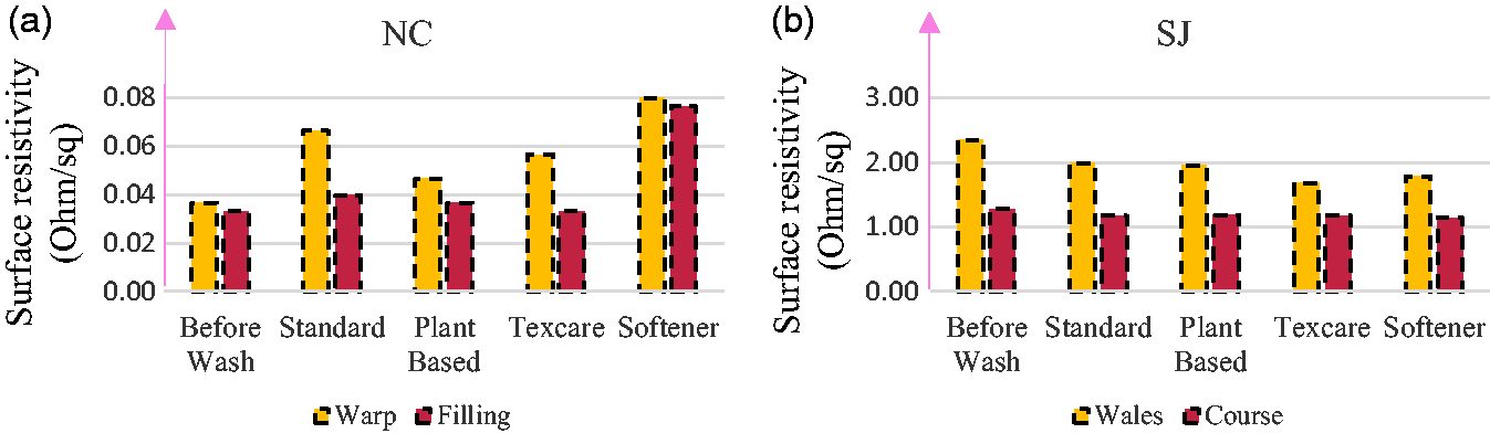
Taber abrasion
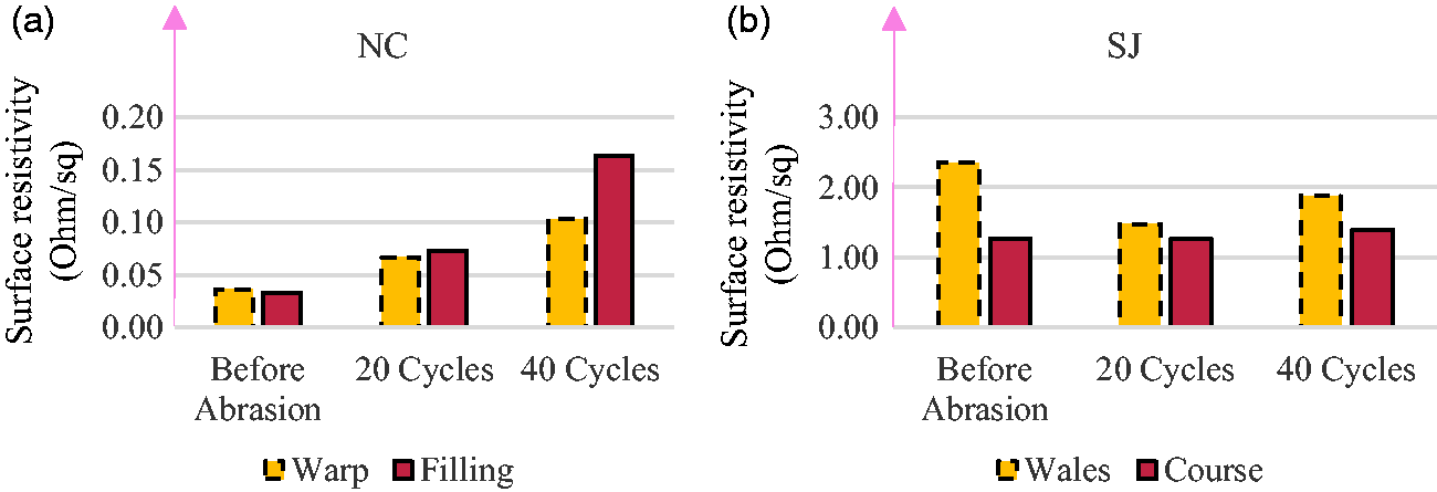
Abrasion tests were conducted following ASTM D3884. To explore resistivity changes after varying degrees of abrasion, specimens were subjected to 20 and 40 abrasive revolutions. As evident in Figure 7, 40 cycles caused considerably more damage to the fabric than 20 cycles. Figure 8illustrates resistivity changes after the abrasion test. The surface resistivity of NC increased as the number of abrasive revolutions increased. Conversely, SJ resistivity in the wales direction decreased after abrasion.
Photos of (a) NC and (b) SJ after abrasion test. Abrasion effect on surface resistivity of (a) NC and (b) SJ.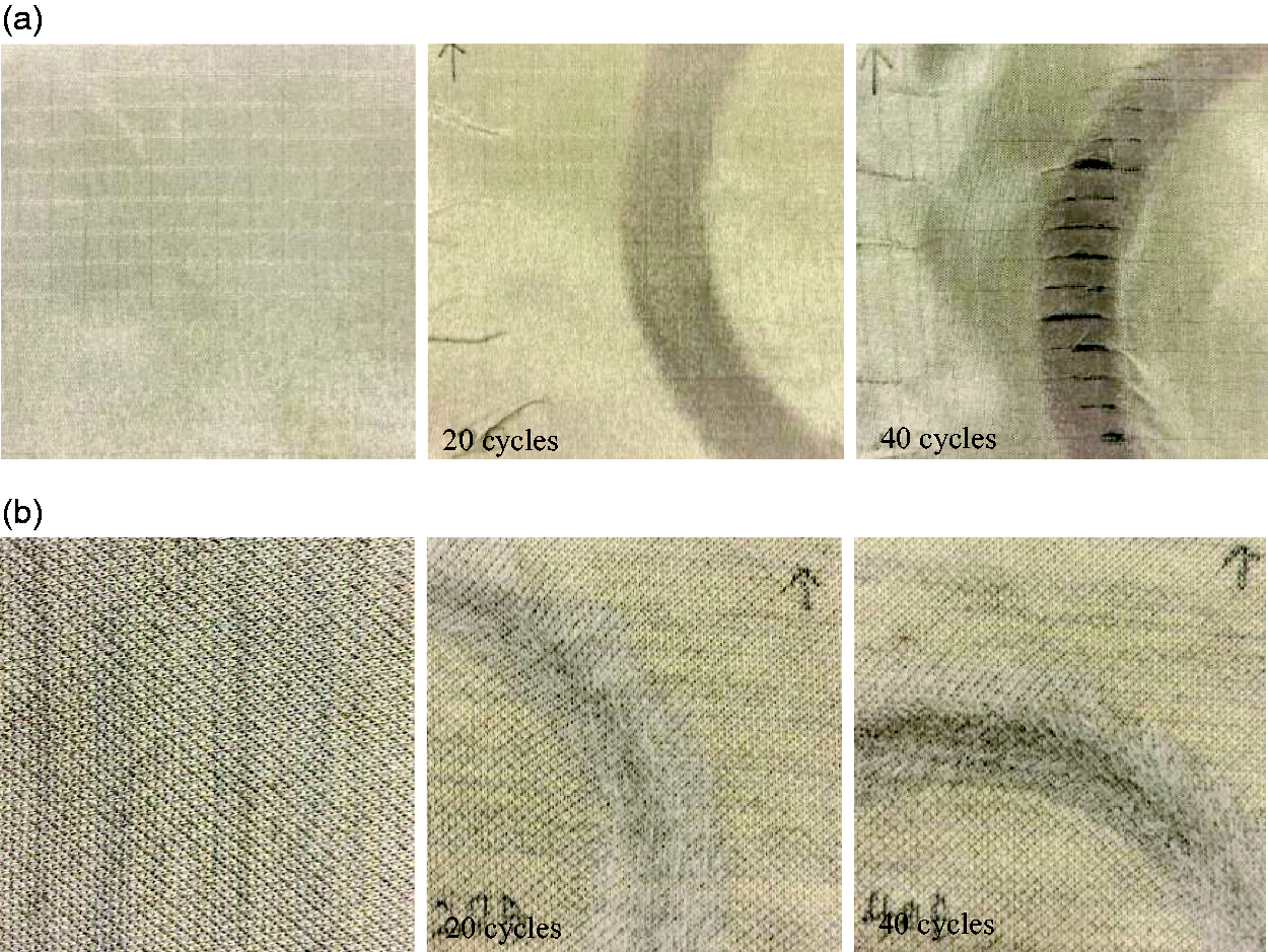
Pilling
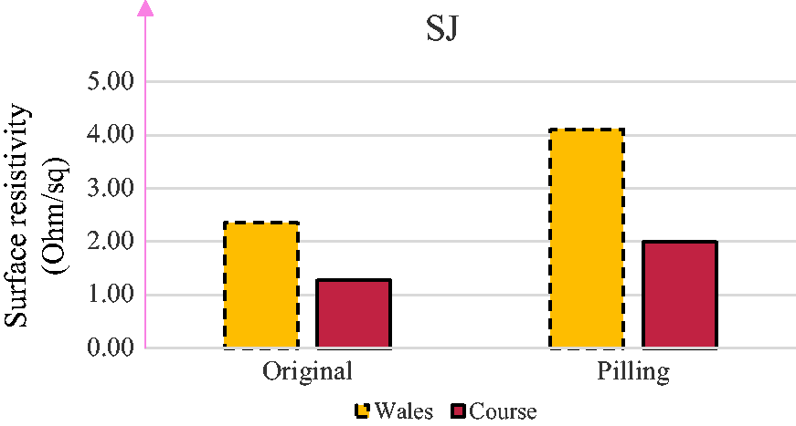
The surfaces of e-textile specimens were pilled in a random tumble pilling tester following ASTM D3512. After 30 min of tumbling, NC showed no visible pilling – receiving a rating of 5 on the photographic standards for random tumble pilling test. However, it did curl significantly (as shown in Figure 9(a2)), and became completely non-conductive. The SJ fabric did not curl, but pilled to a rating of 4 (as shown in Figure 9(b2). Note: the photo of the SJ after pilling test was magnified to clearly show the pilling (napping of fibers) on the textile surface. Its surface resistivities increased by 1.7 and 0.7 Ω/sq., respectively, in wales and course direction (Figure 10).
Photos of NC (a1) pre- and (a2) post-pilling test and SJ (b1) pre- and (b2) post-pilling test. The surface resistivity of SJ before and after pilling test.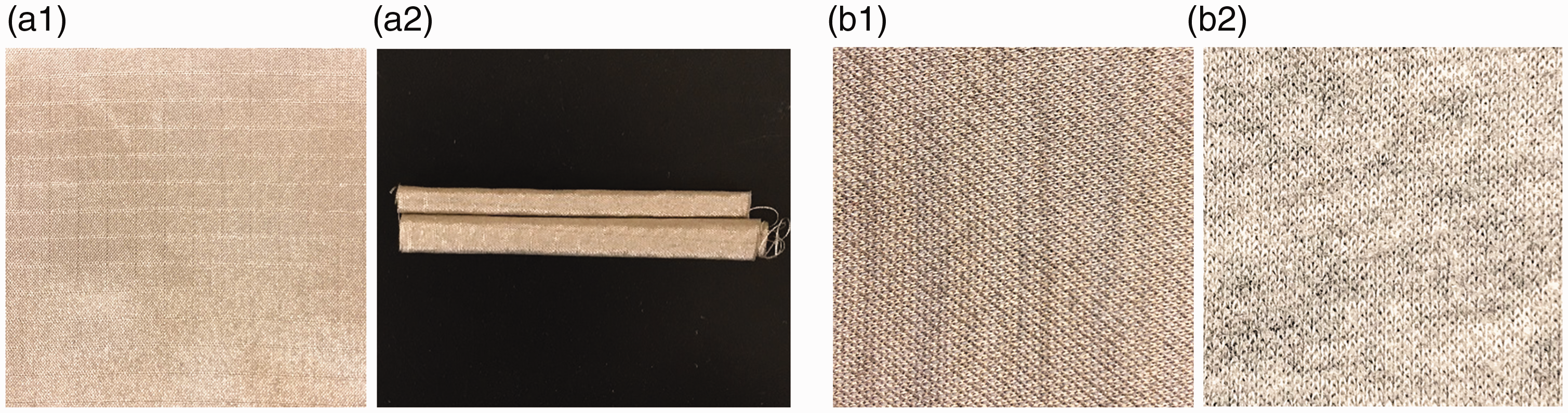
Wrinkle
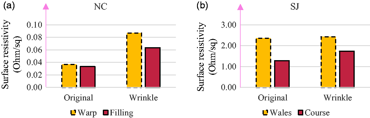
Wrinkles were induced in e-textile specimens as outlined in AATCC TM128. Specimens remained in the AATCC wrinkle tester under a 3500gload until reaching a rating of 1 (as shown Figure 11(a2)and 11(b2)), as indicated by the AATCC three-dimensional wrinkle recovery replicas. Results suggest that wrinkling slightly increases the surface resistivity of e-textiles. NC had an increase of 0.05 and 0.03 Ω/sq. in the warp and filling directions (Figure 12(a)) and SJ had an increase of 0.07 and 0.46 Ω/sq. in the wales and course directions (Figure 12(b)).
Photos of NC (a1) pre- and (a2) post-wrinkling test and SJ (b1) pre- and (b2) post-wrinkling test. The surface resistivity of (a) NC and (b) SJ before and after wrinkling test.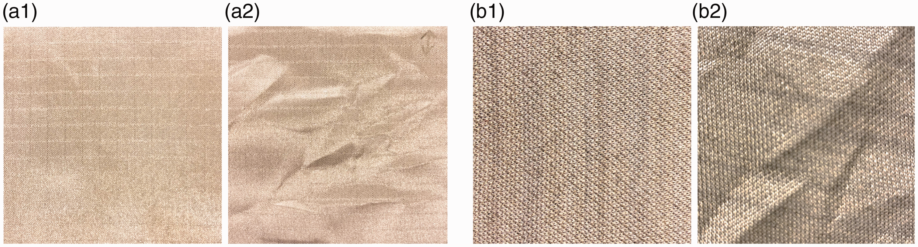
To summarize the effects of durability on e-textile surface resistivity, moisture and laundering did not drastically affect the resistivity of either e-textile. Perspiration residues and abrasion slightly increased the resistivity of NC, but decreased the resistivity of SJ in wale direction. Pilling resulted in severe damage to the resistivities of both fabrics, and wrinkling caused little effect.
Textile antenna design and durability tests
Textile antenna design
The surface resistivity study was conducted at DC frequency. As there is a gap in literature regarding the use of e-textiles for RF, the RF performance of e-textile durability needed to be investigated. A textile antenna was designed and its performance was examined to measure durability following the e-textile resistivity testing structure previously outlined. The textile antenna was designed from the NC fabric as the patch material, as its resistivity was much lower than SJ and more isotropic in different directions than the SJ e-textile. Medium weight denim fabric (100% cotton) was selected as the substrate to create the microstrip antenna. The denim substrate had a thickness of 0.56 mm and a permittivity of around 1.7.
Figure 13illustrates the three-layer patch antenna structure from top and side views, while Table 3outlines the optimized antenna dimensions. Both the top layer (patch) and bottom layer (ground plane) are the NC e-textile (represented in yellow), while the substrate layer (denim) is sandwiched in-between (represented in gray). To securely attach the e-textile patch to the substrate so that no air gap would be present, a very thin fusible bond material (stitch witchery) was applied between the NC fabric and the denim. Because the fusible web is very thin, its influence on antenna performance is negligible.
Textile microstrip antenna. Dimensions of the textile antenna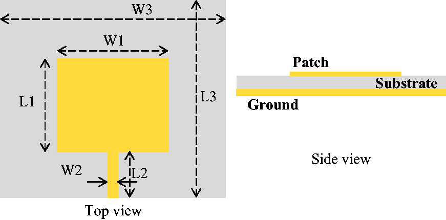
The antenna was designed to operate in the 2.45 GHz ISM (industrial, scientific, and medical) band. In order to compare the textile antenna performance with traditional antenna, two identical antennae were fabricated – one made from copper tape and the other from the NC e-textile. The microstrip antenna made of copper tape was used to verify the textile antenna performance in an open space environment. Both antennae were fabricated following the layered structure outlined above, utilizing the denim substrate. Figure 14illustrates the fabricated prototypes of e-textile antenna and copper antenna. The antenna performance was tested both in open space and on human chest by the network analyzer Agilent PNL N5230C.
Photos of fabricated (a) textile antenna and (b) copper antenna.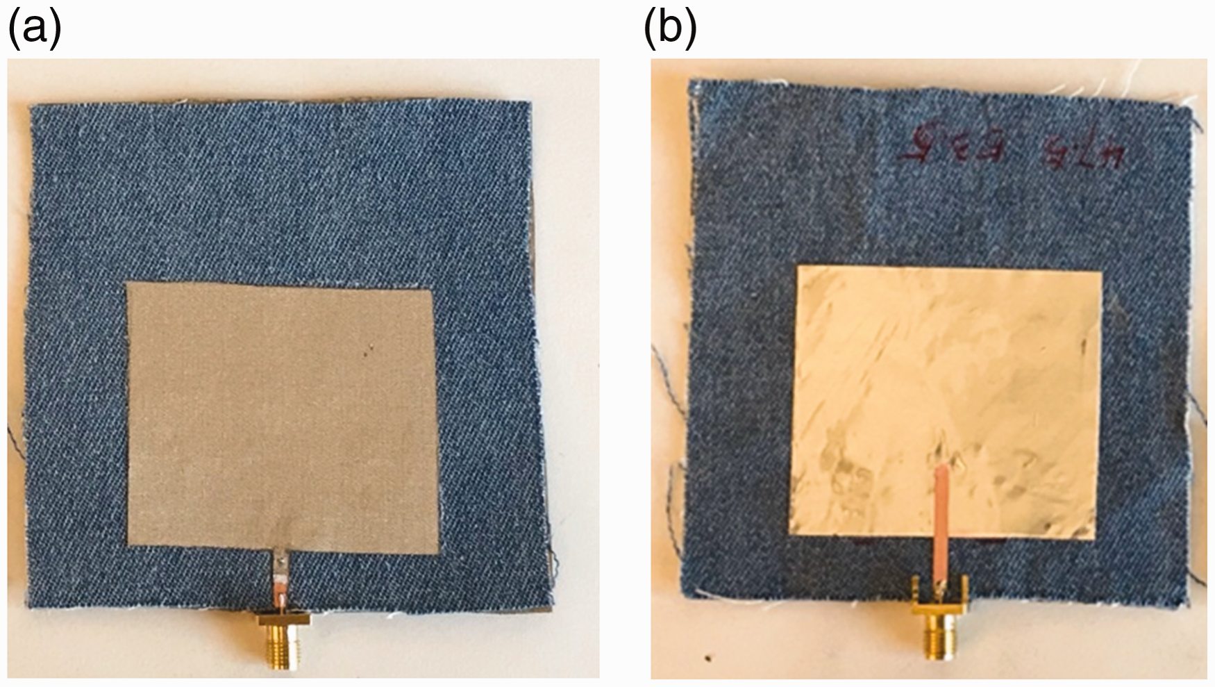
To measure antenna performance, two antenna parameters were explored for open space and human body application: reflection coefficient and realized gain. Reflection coefficient, also known as S11, represents how much electromagnetic energy is reflected back at the feeding port. Resonance frequency, which represents the antenna working frequency, can be observed on S11curve at the dip position. Realized gain represents the ability of an antenna to radiate power into the air and focus the power in one direction. In order to have a good communication link, a low reflection coefficient (S11 < −10 dB) and a high realized gain (gain > 0 dB) is desired. Figure 15(a)illustrates the antenna performance measurement setup in open space. The textile antenna was connected to a vector network analyzer (Agilent PNL N5230C) and acted as a transmitting antenna. A standard horn antenna acted as a receiving antenna and was placed 2 m away from the textile antenna. The vector network analyzer can measure the S11and realized gain of the textile antenna. For on body test, similar setup was used except that textile antenna was mounted on the chest, as shown in Figure 15(b).
Antenna measurement setup (a) in open space and (b) on human body.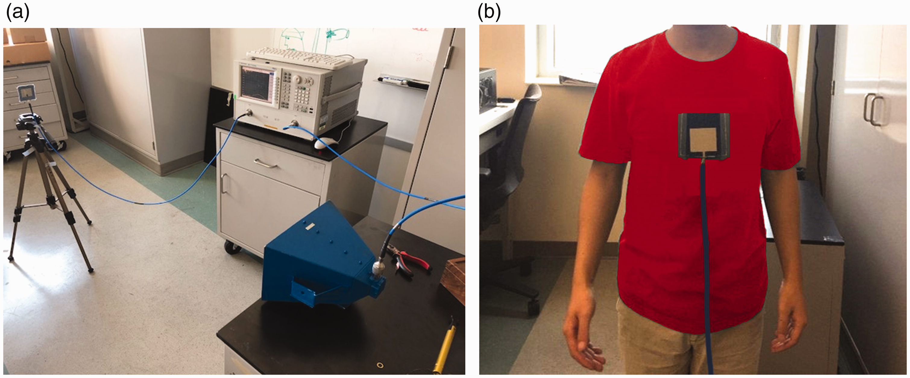
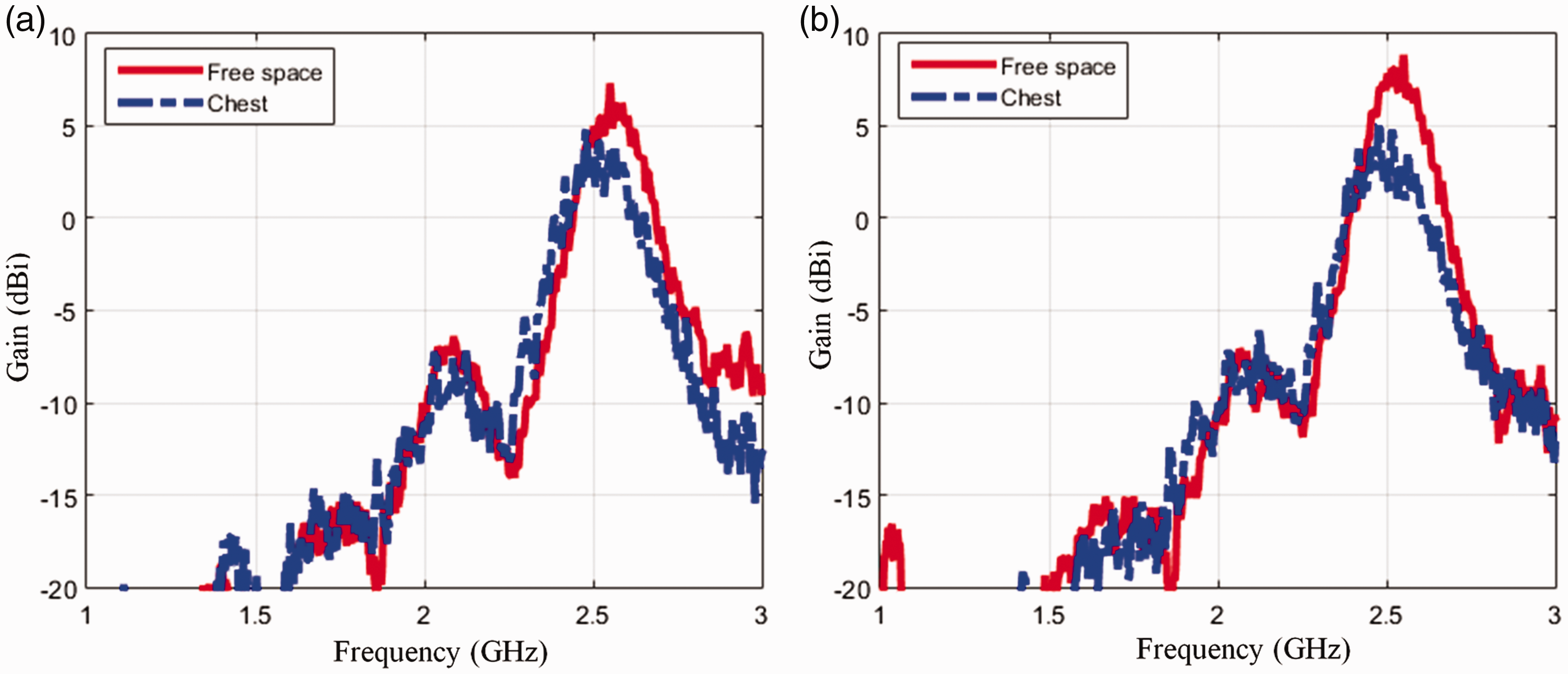
Figure 16shows the measured reflection coefficients S11of both antennae in open space and on human body. It was observed that both antennae resonated around 2.5 GHz in open space, however, the resonance frequency shifted when placed on the human body due to the high permittivity of body tissues. The e-textile antenna achieved a bandwidth of 3% with S11below −10 dB, which was similar with copper antenna performance. Figure 17plots the realized gain of both antennae. It was observed that e-textile antenna could achieve a gain of 5 dB on chest, about 2–3 dB lower than the antenna in open space. This is because body tissues absorbed some of the radiated power. Overall, the e-textile antenna achieved comparable performance with the copper antenna in terms of both reflection coefficient and realized gain. For the remainder of the manuscript, durability performance of the e-textile antenna is primary focus.
Measured reflection coefficient of (a) textile antenna and (b) copper antenna. Measured realized gain of (a) textile antenna and (b) copper antenna.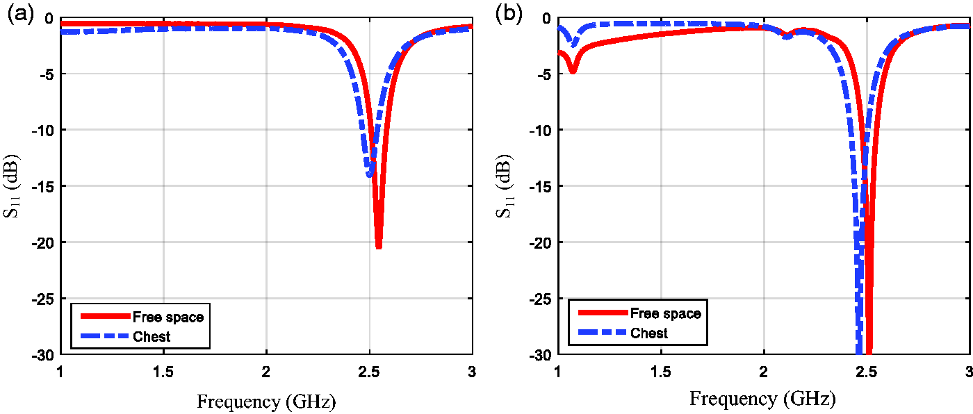
Durability test results on antenna performance
The same durability tests were performed on textile antennae including moisture, laundry, pilling, and wrinkling test. Perspiration effect was not evaluated for NC antenna performance because similar surface resistivity results were achieved in the moisture test. Due to the antenna size limitation, the abrasion test was not conducted. In addition to the aforementioned tests, a strain test on the NC antenna was conducted. This durability test was not performed in the DC surface resistivity portion of this study because the shape distortion caused by strain testing yielded inaccurate surface resistivity measurements.
Moisture
The purpose of this test was to measure the moisture effect on antenna performance. For the moisture test, the antenna was soaked in distilled water for 10 min and then removed to naturally air dry under room temperature (21℃). The antenna performance was measured twice after procedure. One moisture reading was taken approximately 6 h after the initial soak, represented by the dashed curve in Figure 18(noted as “after test – damp”). After the antenna completely dried a second measurement was taken (approximately 18 h of air drying), represented by the black curve (noted as “after test – dry”). It was found that moisture could shift the antenna resonance frequency to a lower value, due to the high permittivity of water. The presence of moisture also caused the antenna gain to drop by more than 10 dB. This is because water can absorb electromagnetic energy and cause degradation to the antenna radiation ability.
Moisture effect on e-textile antenna performance: (a) S11and (b) realized gain.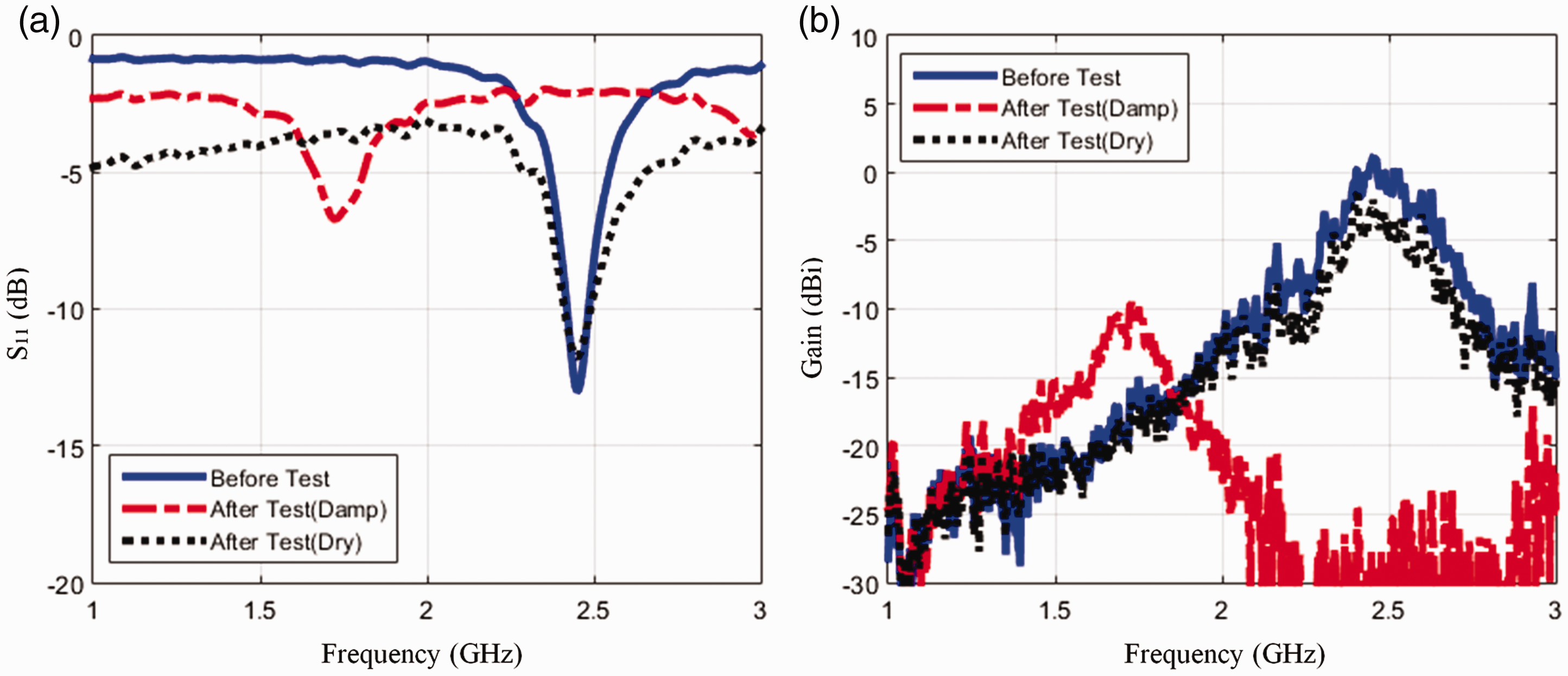
Laundering
This test measured the effect of laundering on antenna performance. AATCC method 61 was followed for this durability test. While four different detergents were tested in the DC surface resistivity portion (findings stated above), all indicated similar influences on e-textile performance and therefore, only standard detergent was used in the antenna performance test to laundering. Similar to the moisture test, antenna performance was measured twice after the accelerated laundering procedure. The initial measurement was taken under damp conditions (6 h of air drying) and the second measurement was performed after the antenna was completely dry (approximately 18 h). Figure 19shows the performance change to laundering. It was found that the antenna resonant frequency shifts from 2.5 GHz to 1.85 GHz and the gain drops by 7 dB when the antenna is damp. This is because water increases the permittivity and loss tangent of the denim substrate. After completely dried, the antenna showed similar performance measurements to the original antenna (pre-procedure).
Laundry effect on e-textile antenna performance: (a) S11and (b) realized gain.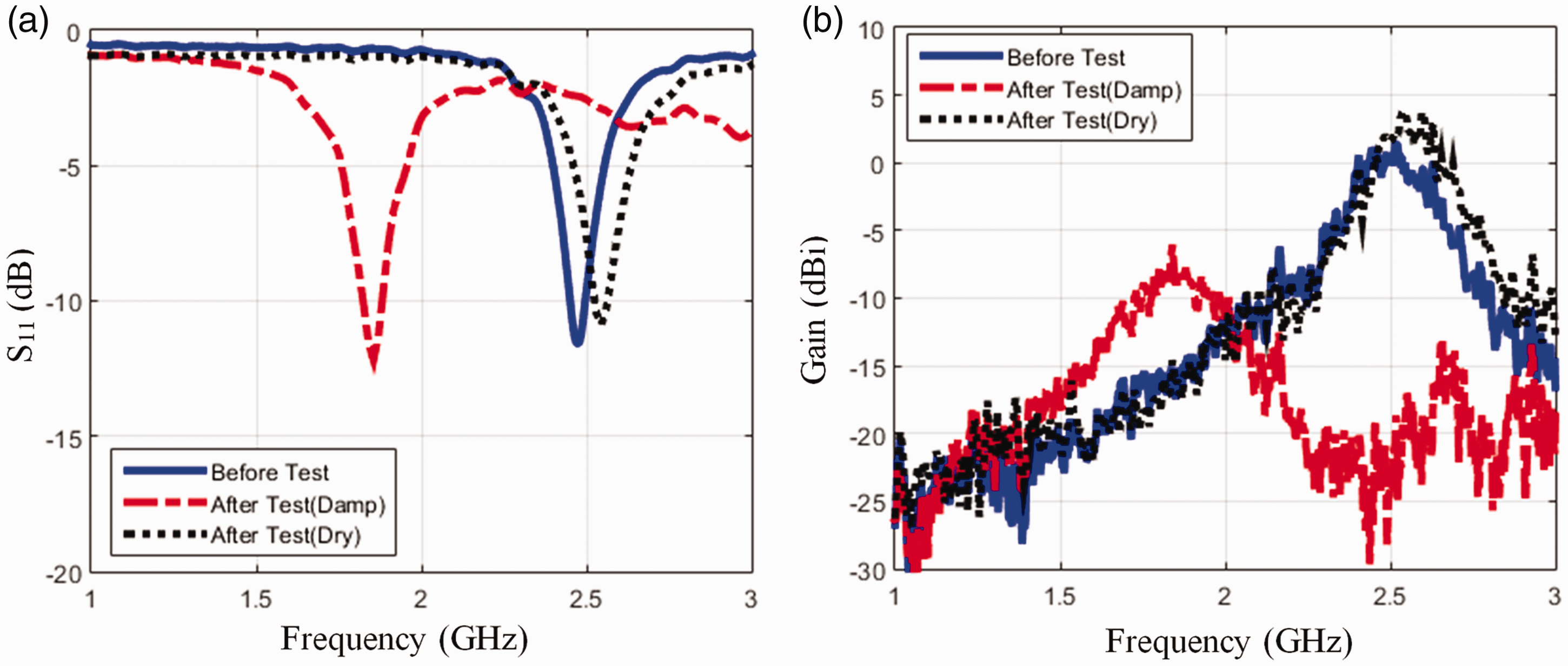
Pilling
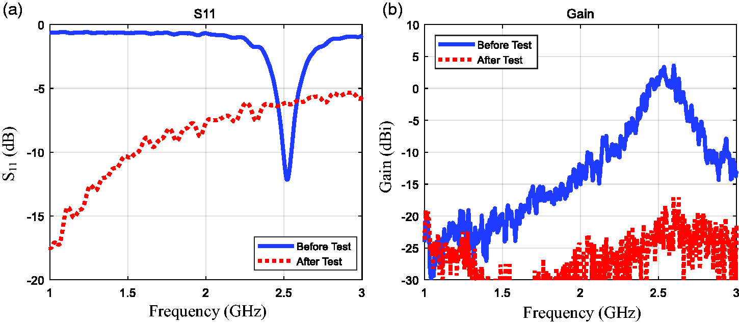
The purpose of this test was to measure the pilling effect on antenna performance. ASTM D3512 was followed for this test. Figure 20(a)and (b) illustrate the antenna appearance change before and after pilling procedure. Figure 21(a)shows antenna reflection coefficient (or S11), where solid and dotted-line curves represent antenna performance pre- and post-pilling test. The solid-line curve has a dip around 2.5 GHz, indicating that the antenna resonates at around 2.5 GHz. The resonance disappears after the pilling test. Figure 21(b)shows the antenna gain, which represents how well the antenna can focus its radiation beam in one direction. It was found that the gain drops almost 20 dB. Thus, it is suggested that pilling, experienced in normal wear, may cause severe damage to antenna performance. Findings agree with the DC resistivity study that NC fabric becomes non-conductive after pilling procedure.
Photos of textile antenna (a) pre- and (b) post-pilling test. Pilling effect on e-textile antenna performance: (a) S11and (b) realized gain.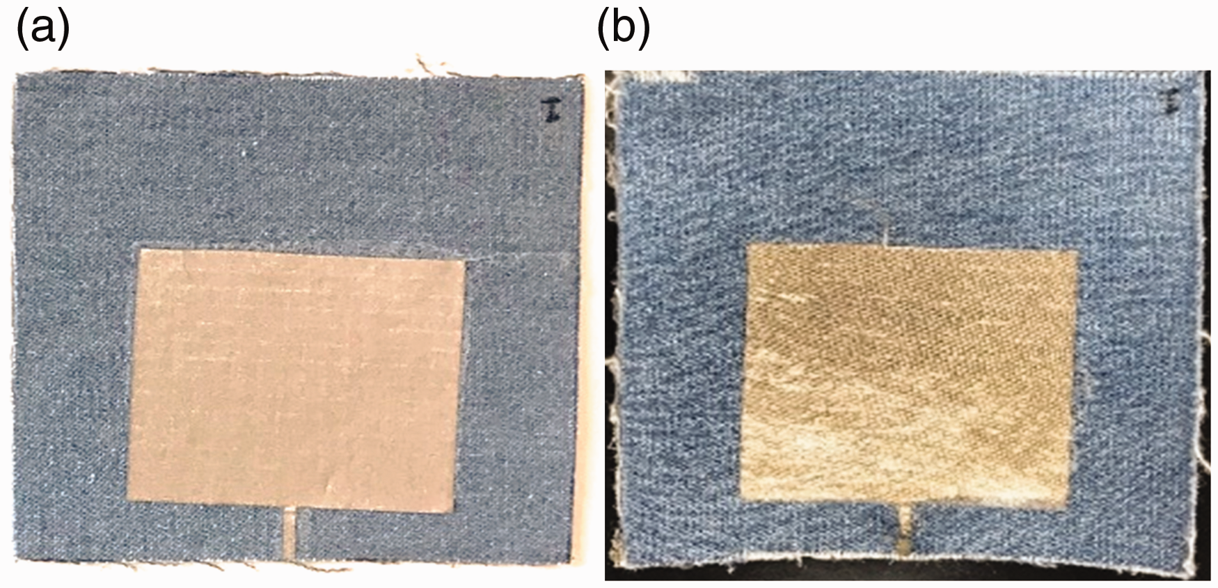
Wrinkle
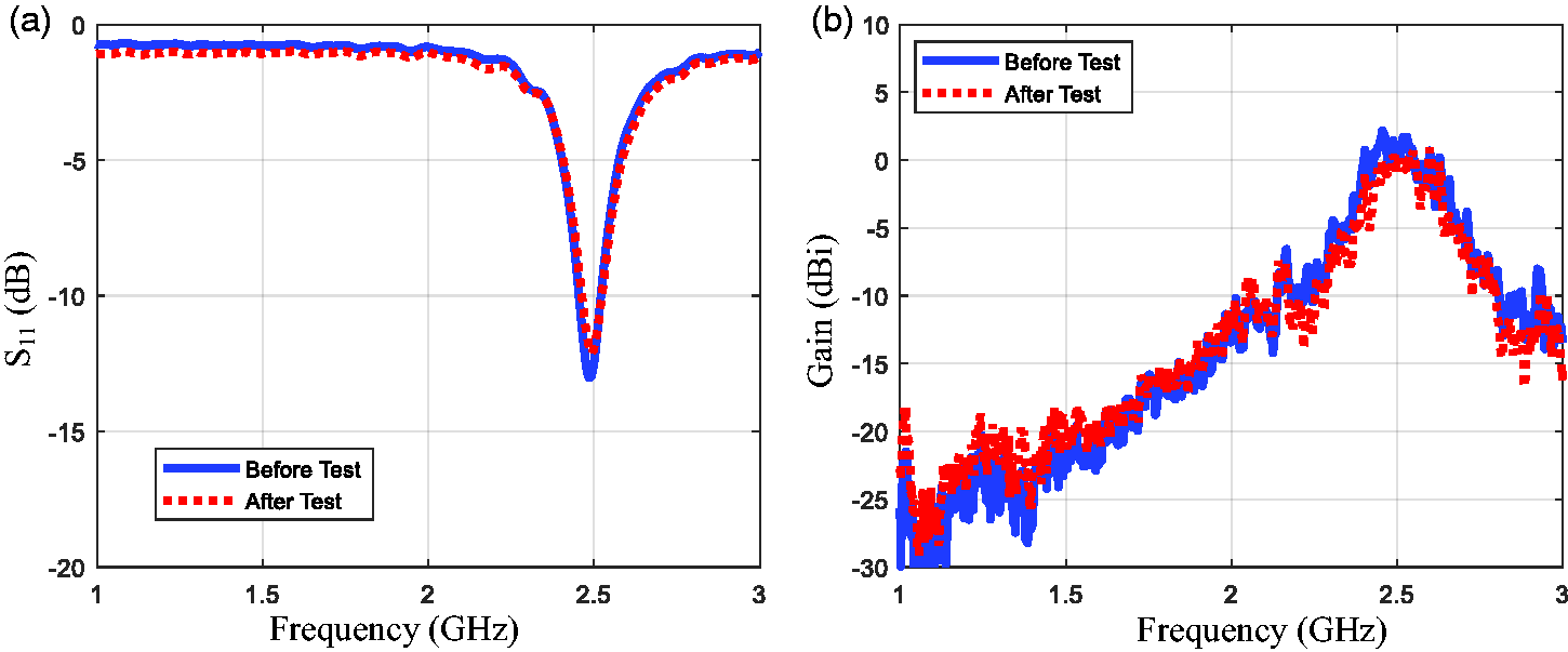
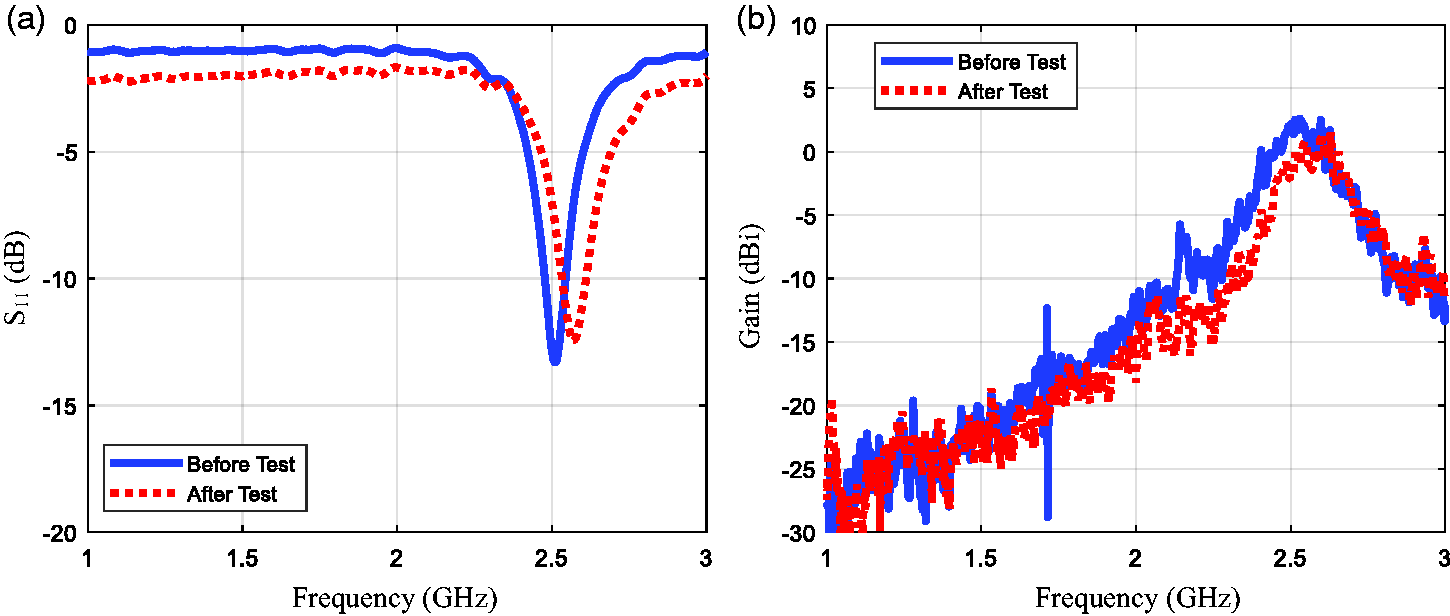
This test measured the wrinkle effect on antenna performance. The AATCC 128 was followed for this test. Figure 22(a)and (b) shows the antenna appearance before and after the wrinkling procedure, indicating apparent wrinkle lines (particularly on the patch). Some wrinkles can be clearly seen on Figure 22(b). Figure 23shows the antenna performance change pre- and post-wrinkling test. It is found that the wrinkling does not affect the antenna performance. Resonant frequency does not change and the antenna gain only drops by 2 dB.
Photos of e-textile antenna (a) pre- and (b) post-wrinkle test. Wrinkle effect on e-textile antenna performance: (a) S11and (b) realized gain.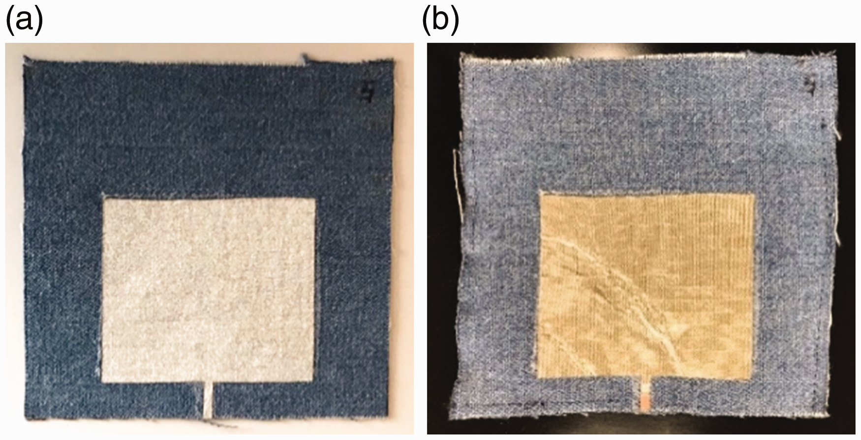
Strain
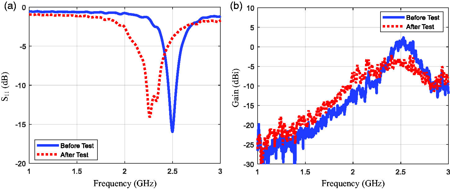
The purpose of this test was to measure strain effect on antenna performance. ASTM D5034 was followed in this straining procedure. The antennae were pulled in vertical and horizontal directions, respectively. Figure 24shows the antenna photos after strain procedure. It was observed that the patch size in the vertical and horizontal directions clearly increased by approximately 4 mm and 3 mm, respectively. Figure 25and 26illustrate the antenna performance change after the antenna specimen was pulled vertically and horizontally in separate tests. It was found that pulling the patch antenna vertically decreased the resonance frequency (as shown in Figure 25(a)), as the side length L increased, which directly determined the resonance frequency. The gain dropped by about 5 dB (as shown in Figure 25(b)), because the e-textile tear near the antenna input port blocked the electrical current. However, when antenna was pulled horizontally, its resonance frequency shifted higher (as shown in Figure 26(a)). This is because the side length Lshortened after being pulled horizontally. Gain did not show substantial change.
Photos of e-textile antennas after being pulled (a) vertically and (b) horizontally. Textile antenna (a) S11and (b) realized gain before and after being pulled vertically. Textile antenna (a) S11and (b) realized gain before and after being pulled horizontally.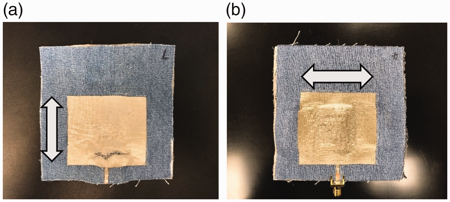
Conclusion
E-textile durability performance was investigated from both DC and RF perspectives. It was found that pilling and abrasion caused a substantial change to e-textile resistivity and antenna (NC) performance. Findings suggest that wearable devices which utilize conductive or substrate components of the e-textiles tested in this study, may lose communication if exposed to pilling or abrasive environments. Wrinkling can slightly increase the e-textile's surface resistivity and cause the antenna gain to drop only by 2 dB. Laundering and moisture can temporarily cause the antenna resonant frequency to shift lower and the gain to drop before antenna is dried, but its performance will return to normal after drying. Pulling the antenna can change its resonance frequency and slightly affect its gain.
Findings of this study provide insight for the integration of e-textile antennas into WBAN and wearables. It is necessary to optimize the placement location of antenna on clothing to avoid abrasion or pilling, as well as acknowledge resistivity performance and recovery when exposed to aqueous environments (moisture, perspiration, and laundering). Based upon outcomes of pilling performance tests, it would be desirable to develop an anti-pilling e-textile for antenna application. Findings of this study suggest life span estimations of smart clothing that utilizes the tested e-textiles due to potential abrasion or pilling damages that may occur during daily life. Durability tests conducted in this study provide baseline information on performance capabilities and limitations of e-textiles for potential applications in military, sports and/or wellness industries. While e-textile challenges remain for mass integration in wearables market, results of this study provide understanding and optimism for designing and implementing wearable antennas that are low profile, lightweight, and flexible.
Suggestions for future research based upon findings of this study includes the sampling of additional e-textile fabrics available on the market since only two were investigated and discussed in this work. Research is also planned to refine durability test protocols which can be extended to other types of e-textile fabrics (whether electronic component is integrated or applied). Additionally, future research involves the development of a new e-textile antenna measurement system that may replace the current bulky and expensive vector network analyzer measurement system.
Footnotes
Declaration of conflicting interests
The authors declared no potential conflicts of interest with respect to the research, authorship, and/or publication of this article.
Funding
The authors disclosed receipt of the following financial support for the research, authorship, and/or publication of this article: This work was supported by the Baylor University Research Committee (URC) Small Grant Program (Grant No. 30330440).