
Abstract
In this paper, a kind of T-shaped hook-connected structure, which consists of a T-shaped plate made of two-and-a-half-dimensional woven composites and a groove structure made of T300/BMP316 laminated composites, was designed as the simulator specimen of the connection structure between the vane and the case in an aero-engine. As the bending strength and tensile strength are important mechanical properties, bending tests and tensile tests, respectively, of the T-shaped hook-connected structure were conducted to study the mechanical properties and failure modes under bending and tensile loads on web. Experimental results showed that the initial damages both occur at the root-edge, and then the damages extend to the root-middle during the bending test or extend perpendicular to the root-edge to the margin of the flange during the tensile test. Then, a strength prediction method based on the progressive damage theory was developed to simulate the mechanical properties and damage processes of the T-shaped hook-connected structure under bending and tensile loads, respectively. Compared with experimental results, the maximum error is less than 10%, and the damage modes are similar.
Keywords
Due to their low density and excellent mechanical properties, composites have been widely used in industries such as aerospace, marine, motor sport, military and specialist construction. 1 With the development of heat-resistant resin, carbon fiber resin matrix composites can be used to replace some conventional metallic fabrications in aero-engine applications, which will yield a 20–30% weight saving and 25% reduction in cost. 2 It is reported that both the front fan case and fan blades of the GEnx commercial jet engine, which is one of the current most advanced aero-engines, are made of carbon fiber composites. In the past few decades, there have been many studies on the mechanics of laminate composites and three-dimensional (3D)/two-and-a-half-dimensional (2.5D) woven composites, which are the two typical types of composite structures used widely in engineering. Normally, laminate composites are applied as the engine case as the size of the case is large. Considering that the vanes or blades will be subject to out-of-plane loads during service, 3D or 2.5D woven composites will be feasible for the vane or the blade due to their favorable delamination resistance properties. Therefore, it is urgent and important to design a connected structure between the laminate composites case and the woven composite vane during the design process of aero-engines. According to traditional design experiences, a T-shaped hook-connected structure is one of the valuable connection structures due to its convenient dismounting and simple mechanism. 3
T-shaped structures are one of the common structures that are widely used in engineering. Recently, there have been many studies on their mechanical properties. Li et al. 4 investigated the residual stresses and the curing deformation of an integrated T-shaped composite structure using different curing strategies by a 3D incremental viscoelastic constitutive equation. Mouritz 5 investigated the pull-out mechanical properties of unpinned and z-pinned carbon fiber–epoxy T-shaped joints in a hot (75℃) and humid (85% relative humidity) environment. Hélénon et al. 6 studied the out-of-plane bending strengths and failures of T-shaped laminated composite structures with loads at angles of 0°, 45° and 90°, respectively. Ouyang et al.7,8 studied the bending fatigue behavior of the flange in a 3D five-directional braided T-shaped composite from finite element analyses and experimental characterizations. Most of these studies only focused on the mechanical properties of T-shaped structures. There are few studies on the mechanical properties of the T-shaped hook-connected structure. The bending strength and the tensile strength of the T-shaped hook-connected structure are its main mechanical properties, as it will suffer the bending and tensile loads on the web caused by airflow shock during service. Zhang et al. 3 studied the bending/tensile properties of T-shaped hook-connected structures made of 2.5D woven composites by simulations and tests. However, there is little information about the bending/tensile properties of T-shaped hook-connected structures between 2.5D woven composites and laminate composites.
In this paper, a kind of T-shaped hook-connected composite structure was designed as the simulator specimen of the connected structure between the vane and the case, firstly. Then, bending/tensile tests were conducted to study the bending/tensile mechanical properties and failure modes. Finally, a strength prediction method based on progressive damage theory was developed and used to simulate the mechanical behaviors and damage process under bending/tensile loads on web, respectively.
Experiments and results
Experimental equipment and procedures
A kind of T-shaped hook-connected composite structure was designed and used for the bending test and tensile test, respectively. Figure 1(a) shows the 3D model of this structure, which comprises a T-shaped plate and a groove plate. Figure 1(b) shows its exact geometric size; the T-shaped plate comprises a flange and a web, which are 75 and 100 mm in length, respectively. The groove plate is 200 mm in total length, and its groove is designed to be 100 mm in length to ensure the flange of the T-shaped plate can be embedded in the groove exactly. The groove plate is made of T300/BMP316 carbon/polyimide laminated composites in which the fiber volume fraction accounted for 48.62%, and its stacking sequence in different parts (three parts) is shown in Figure 1(c). The T-shaped plate is made of T300/WSR618 (E-51) 2.5D woven composites; its woven parameters are shown in Figure 1(d), in which the fiber volume fractions accounted for 42.94%.
The exact geometric size and the shape of the T-shaped hook-connected structure: (a) three-dimensional model of the T-shaped hook-connected structure; (b) geometric size; (c) groove plate made by laminated composites; (d) T-shaped plate made by two-and-a-half-dimensional woven composites.
The T-shaped plate of 2.5D woven composites was pressed and formed by the resin transfer molding (RTM) process, which can be divided into the following three steps:
weave the preform with carbon fiber and put it into the cavity; inject the resin into the closed cavity under pressure or vacuum, infiltrating the fiber and demolding after curing; secondary processing of the demolded specimen.
The groove plate of laminated composites was manufactured by the lamination process, which includes the following two steps:
dip the T300 carbon fiber cloth in BMP316 polyimide resin and dry it into prepreg; stack the 48 layers of prepreg as shown in Figure 1(c), put it into an autoclave and press mold at some temperature and pressure.
The bending tests of the T-shaped hook-connected structure were conducted on a ZYSS-100, a kind of electro-hydraulic servo biaxial testing machine, shown in Figure 2(a). The transverse push load was applied on the web of the T-shaped plate by a rotating shaft on the head of a push-rod, shown in Figure 2(c) during the bending test. The initial position applied by the push load was 20 mm away from the top end of the web. The flange was constrained by the groove plate, which was fastened by a bending-fixture, shown in Figure 2(d). In order to obtain the strain data during the bending tests, the data acquisition instrument was attached on the back of the T-shaped plate. After all preparations of equipment and instruments, the data acquisition instrument was turned on, the acquisition frequency was adjusted to 5 Hz and the pushing rate was controlled around 2.4 mm/min for the entire test.
Test equipment and the positions at which strain gauges were attached: (a) bending test site; (b) tensile test site; (c) push-rod; (d) bending-fixture; (e) tensile-fixture; (f) the positions of strain gauges (1)–(4).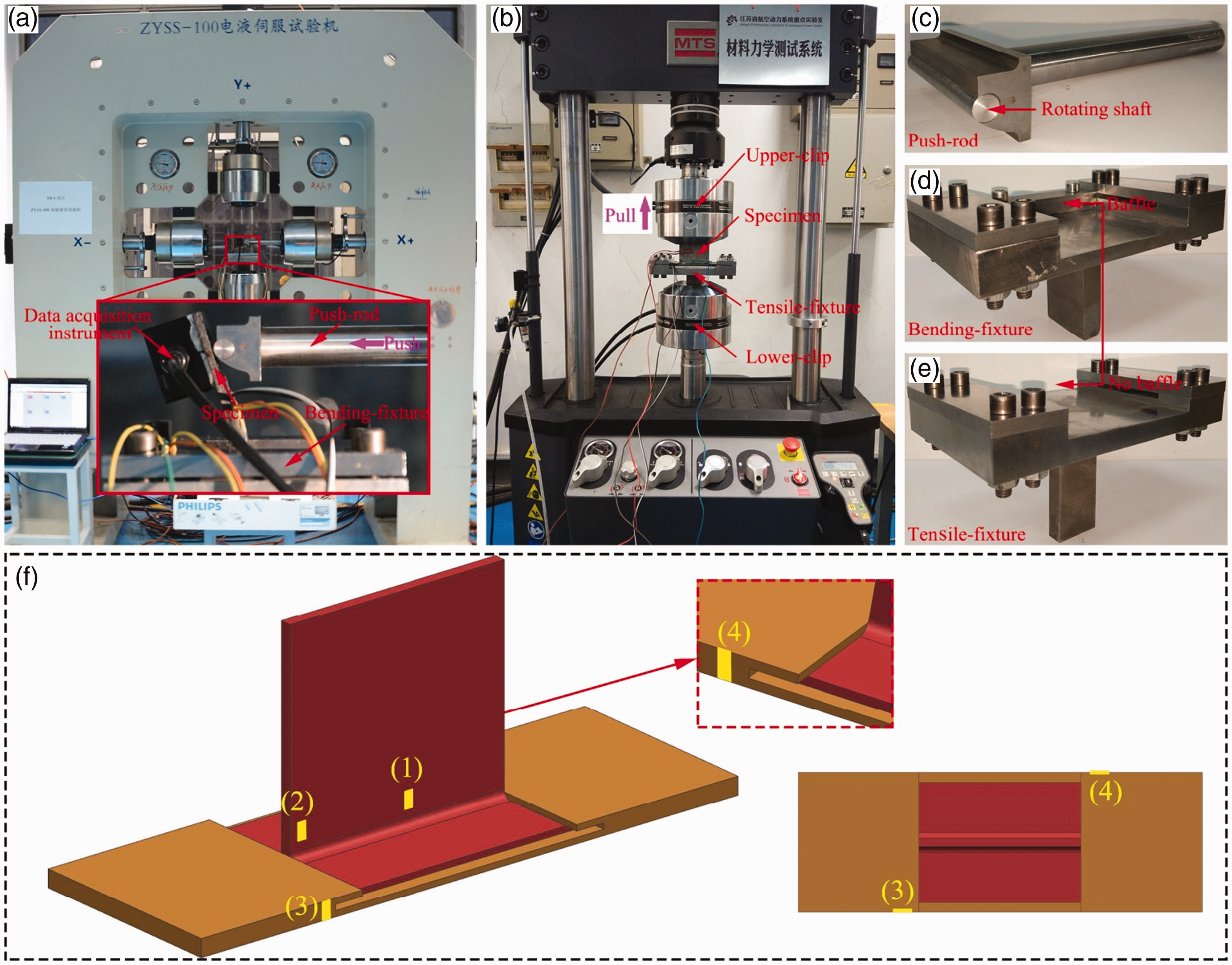
The tensile tests of the structure proposed in this paper were carried out by an MTS landmark material mechanics test machine, shown in Figure 2(b). During the tensile test, the top end of the web was clipped by an upper-clip and tensile loads were applied. The web of the T-shaped plate was pulled at a rate of 1 mm/min for the entirety of the test. Moreover, the groove plate was fixed by a tensile-fixture, which constrained by a lower-clip, shown in Figure 2(e).
Considering the determined complexity of the initial damage and the final destruction of the T-shaped hook-connected structure, several strain gauges were attached at various positions around which it will be easy to crack to judge the damage situation. When there no damage occurred, the values obtained by the strain gauges will vary normally with the increase of loads. Once a crack occurs in the region near the strain gauge, the strains obtained by this strain gauge will be changed obviously because of the release of the constraints in this region. Figure 2(f) shows the positions at which the strain gauges were attached. Strain gauges (1) and (2) were attached at the positions near the root-middle and root-edge of the web on the T-shaped plate, respectively; strain gauges (3) and (4) were attached at different sides near the groove-edges of the groove plate.
Experimental results
The results of the bending test are illustrated in Figures 3(a) and (b). At 288 s, the curve slope of strain gauge (2) changed from positive to negative and the load-time–displacement curve of the bending test appeared to have a small but steep drop, because of the release of the constraints in the region near strain gauge (2), which indicates that the initial damage occurred at the root-edges. Then, the curves of strain gauges (4) and (3) rose steeply in turn at 320 and 400 s, respectively, and the load-time–displacement curve of the bending test appeared to have a small but steep drop again at 320 s, because the delamination failures occurred at the groove-edges successively, meaning strain gauges (4) and (3) failed. At 620 s, the curve slope of strain gauge (1) also changed from positive to negative and the load-time–displacement curve of the bending test reached its highest point, indicating the crack had extended from the root-edge to the root-middle.
Bending and tensile test results: (a) strains of the bending test; (b) curve of load-time–displacement of the bending test; (c) strains of the tensile test; (d) curve of load-time–displacement of the tensile test.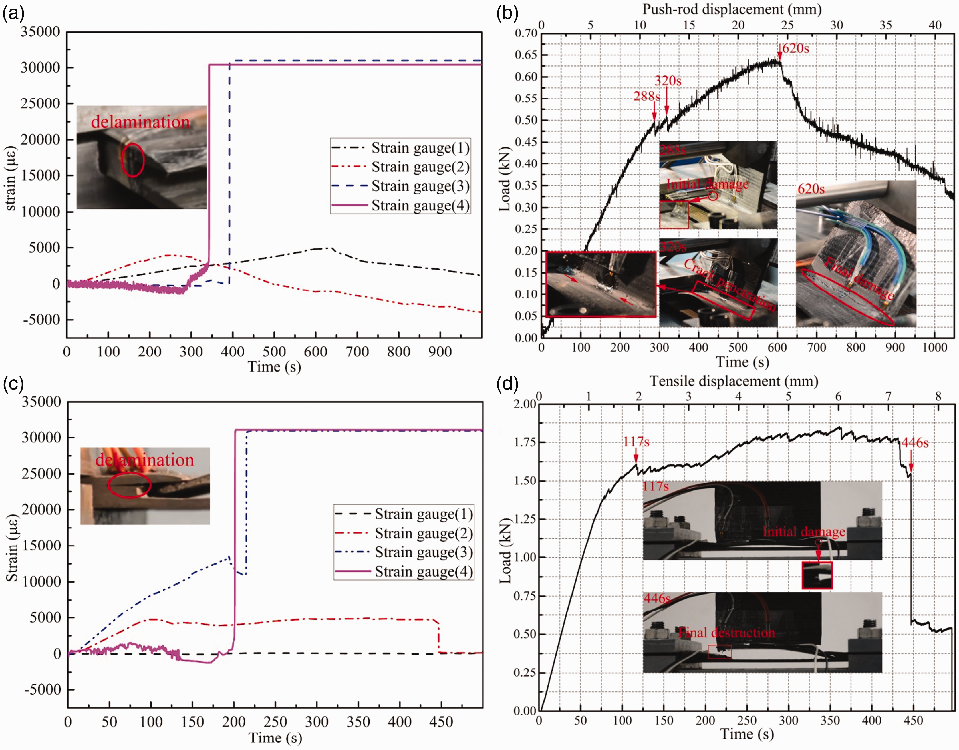
The results of the tensile test are presented in Figure 3(c) and (d). At 117 s, the curve slope of strain gauge (2) changed irregularly and the load-time–displacement curve of the tensile test dropped abruptly, which represents the occurrence of initial damage at the root-edge. Around 200 s, the curves of strain gauges (4) and (3) successively appeared to have steep increases, indicating the failures of these two strain gauges caused by the delamination failures near the groove-edges in the groove plate. At 446 s, the curve slope of strain gauge (2) changed dramatically and the load-time–displacement curve of the tensile test dropped vertically, which means that the edges perpendicular to the root-edge on both sides of the web were broken suddenly, namely the entire structure was destroyed and lost its bearing capacity. Moreover, the strain of strain gauge (1) during the tensile test was almost zero, showing there is no damage in this point.
As shown in Figures 3(b) and (d), the trend of the load-time–displacement curve increased slowly and decreased slowly in the bending test, but increased slowly and then experienced a period of stabilization and finally dropped steeply in the tensile test. This revealed that tensile damage progression obviously has a stalemate stage and transient breaking phase, but the bending process does not. The reason for this phenomenon is that the matrix cracking of the bending test, from the root-edge to the root-middle and then to the interior of the root, was slow and obvious because of the reinforcement of fibers. However, there was almost no crack propagation during the tensile test, which because the flange of T-shaped plate was bent by the tensile load after the damage initiation, until it broke suddenly.
Strength prediction method for the T-shaped hook-connected structure
Stress analysis based on progressive damage theory
In this paper, the representative volume element (RVE) of 2.5D woven composites was developed based on the assumptions that the cross-section of the warp is a rectangle and the cross-section of the weft is a biconvex lens. 9 During simulation of 2.5D woven composites, a finite element can represent a RVE, and the equivalent mechanical properties of the element can be calculated based on the RVE. The laminate composites were analyzed based on the classical laminate theory.
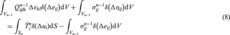
The progressive damage theory10,11 was used for strength prediction of the T-shaped hook-connected structure. When the external load P
i
(i = 1, 2, 3…) gradually increased to the nth step, the equilibrium equation of load can be expressed as


Then substituting Equation (4) into Equation (3), one obtains

Moreover, the increment of strain


Then, substituting Equations (6) and (7) into Equation (5) and omitting high-order items, one obtains
Through transforming Equation (8) by the variational method, a set of linear equations for the displacement increment can be obtained and then solved by the finite element method (FEM). As the load increases, damage will occur inside the structure and the stiffness matrix of the damaged area will degenerate, then the internal stress of the stress will be redistributed, so that it will be recalculated using Equation (8). The specific FEM procedure of the strength prediction is shown in Figure 4.
Finite element method (FEM) procedure of progressive damage theory.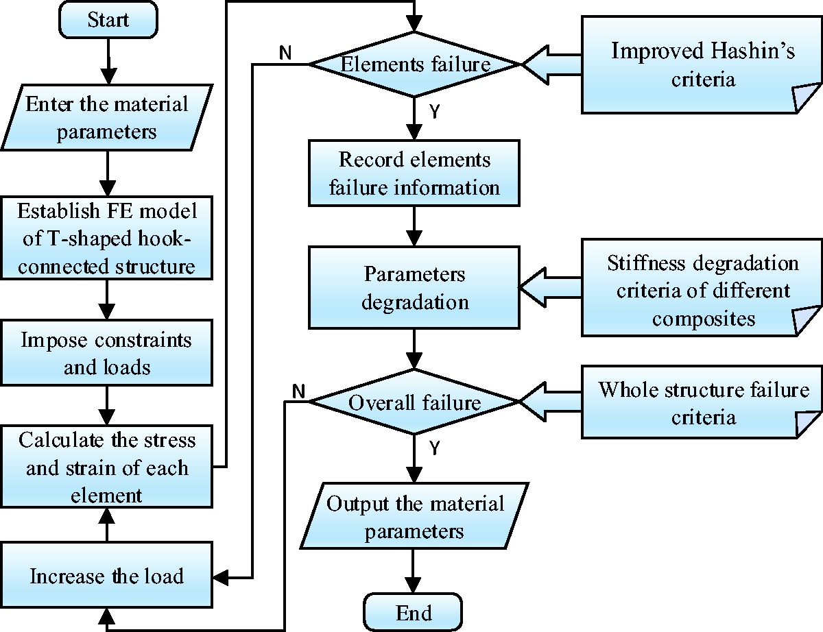
Some failure criteria used in this paper
Failure criteria of elements and the entire structure
Different damage modes and their failure criteria for different composites
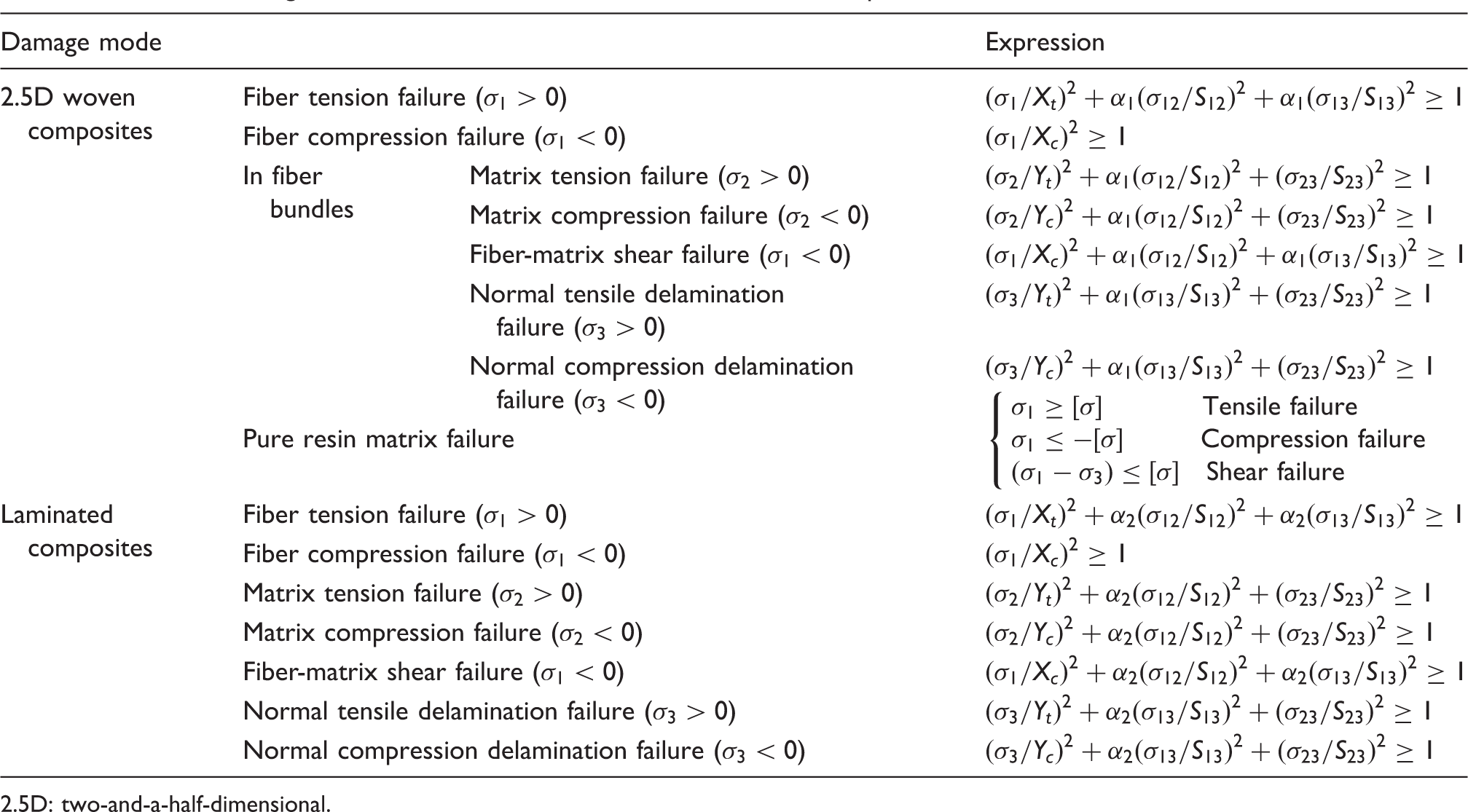
2.5D: two-and-a-half-dimensional.
Moreover, the entire structure can be considered as completely destroyed when the following conditions are met: (a) the fatal failure elements account for more than 70% of the total damage elements on the whole root during the bending process; (b) the fatal failure elements account for more than 70% of the total damage elements on the edge perpendicular to the root-edge during the tensile process.
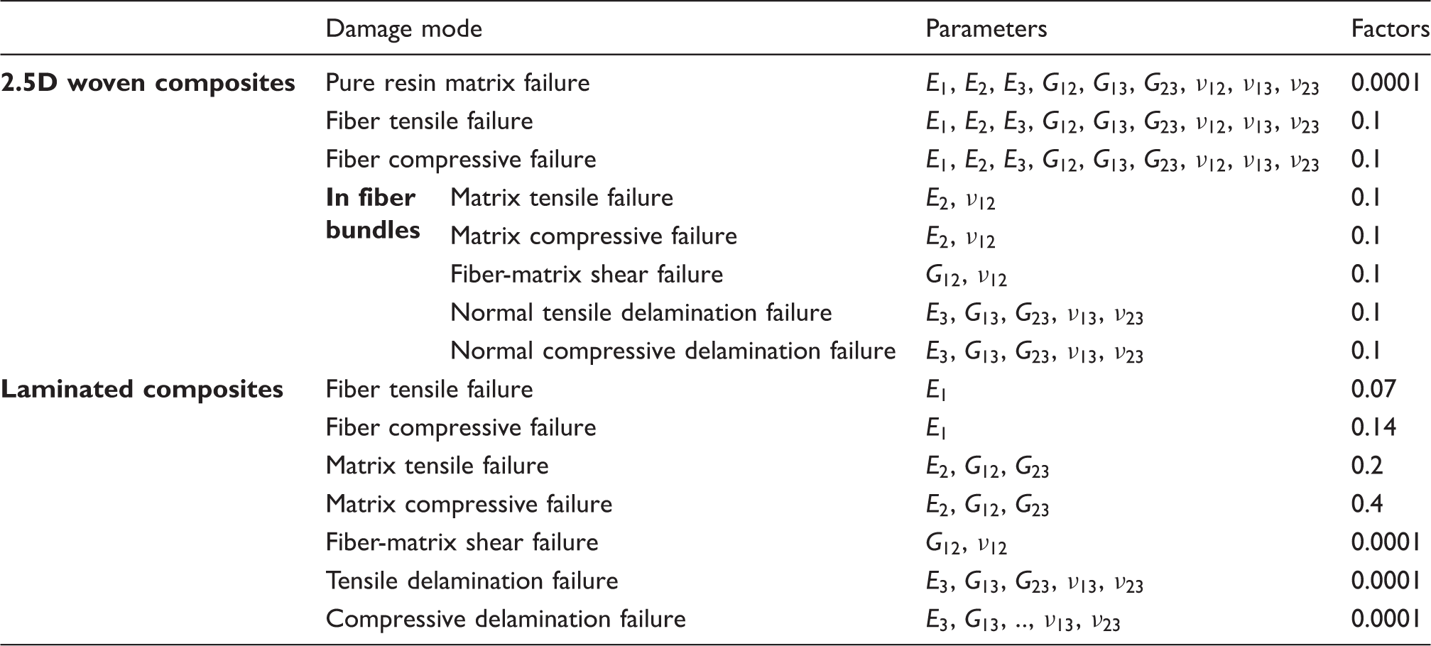
Stiffness degradation criteria for different composites
Stiffness degradation criteria for different two-and-a-half-dimensional (2.5D) woven composites and laminated composites
Simulation results and discussion
Simulation settings
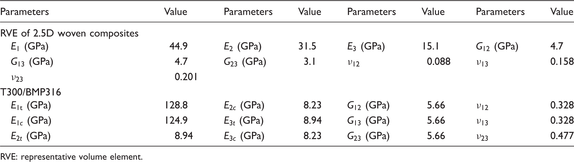
Based on the above strength prediction method, the FEM was used to simulate the bending/tensile processes of the T-shaped hook-connected composite structure. Tables 3 and 4 show the elastic properties and the strength properties of the 2.5D woven composites and the T300/BMP316 monolayer plate.
14
Moreover, Figure 5 shows the settings of boundary conditions and meshes. First, uniform surface loads and tensile surface loads were applied on the web of the T-shaped structure to simulate the airflow impact force and centrifugal force in bending simulation and tensile simulation, respectively. The relationship between the uniform surface loads and the experimental bending loads is listed in the Appendix. Second, fix support was applied around the bottom of the groove plate. Third, the contact mode of ‘no separation’ was set between the T-shaped structure and the groove structure. Fourth, SOLID185 (sweep style) and SOLID187 (sweep style) were used to mesh the T-shaped plate and the groove plate, respectively.
Settings of boundary conditions and meshes. The elastic properties of the two-and-a-half-dimensional (2.5D) woven composites and the T300/BMP316 monolayer plate
14
RVE: representative volume element. The strengths of the two-and-a-half-dimensional (2.5D) woven composites and the T300/BMP316 monolayer plate
14
RVE: representative volume element.

Bending simulation results and comparison with tests
Comparisons of load and deflection obtained by simulation and testing
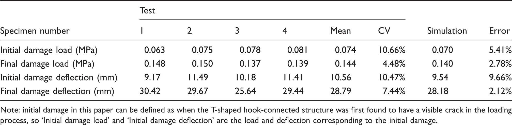
Note: initial damage in this paper can be defined as when the T-shaped hook-connected structure was first found to have a visible crack in the loading process, so ‘Initial damage load’ and ‘Initial damage deflection’ are the load and deflection corresponding to the initial damage.
Figure 6(a) shows the relationships between the tip deflection and load obtained by simulation and testing. The deflection curve obtained by the simulation is slightly larger than that obtained by experiment, but the trends of the two curves are similar. When the load was lower than 0.07 MPa, the curve of tip deformation was linear, but with the increase of load above 0.07 MPa, the curve of tip deformation went into the nonlinear stage. As shown in Figure 6(b), the maximum stresses of the T-shaped plate and the groove plate both changed nonlinearly after 0.07 MPa. When the load was 0.07 MPa, the structure was first found to have some fatal failure at the root-edge, resulting in a decrease in the bending stiffness of the structure, which led to the curve of tip deformation and the curves of maximum stress going into the nonlinear stage. Because of the redistribution of the stress field in the structure, the maximum stress at 0.08 MPa decreased slightly but increased immediately above 0.08 MPa. With the increase of the fatal failure elements, the bending bearing capacity of the structure decreased, resulting in the nonlinearities of the tip deflection and the maximum stress of the T-shaped plate becoming stronger.
(a) The relationship between tip deflection and load obtained by bending simulation and experiment. (b) The relationship between the maximum stress in the structure and load.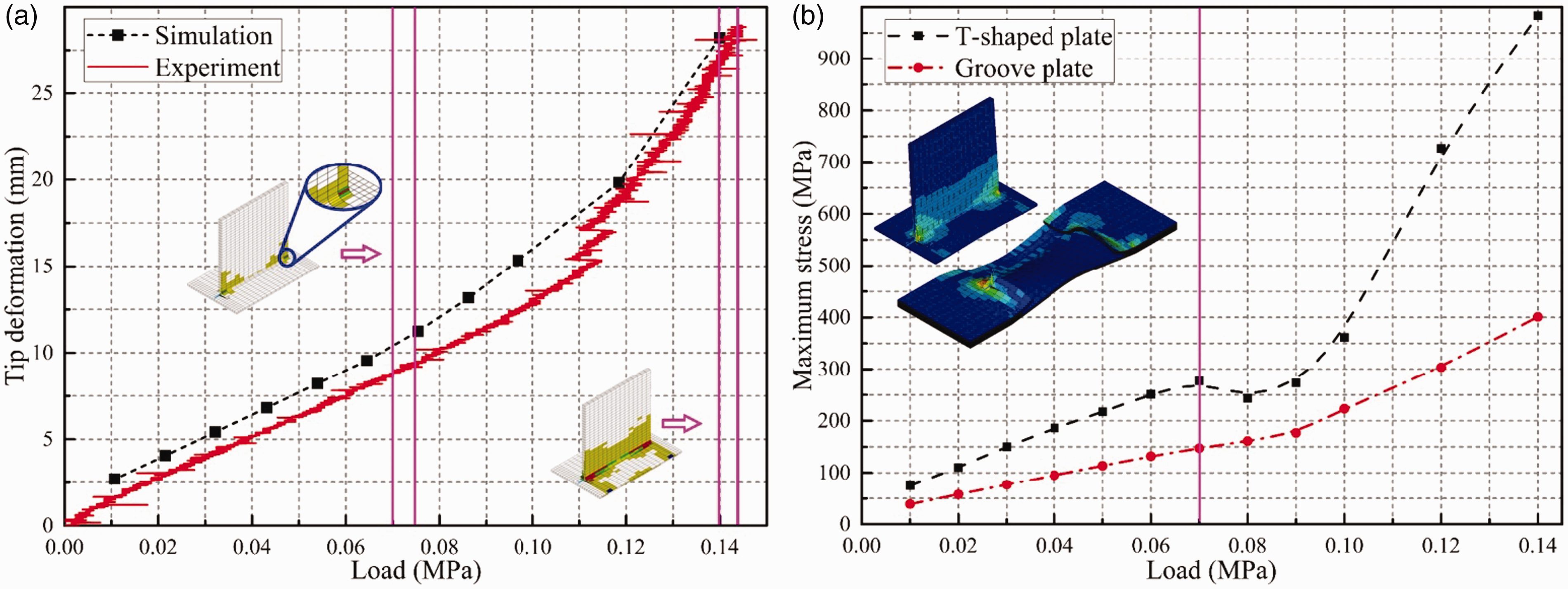
The bending failure process of the T-shaped hook-connected composite structure obtained by simulation is shown in Figure 7. When the load was 0.04 MPa, the structure was first found to have some non-fatal failures at the root-edge in the web because of the stress concentration here. Subsequently, the damage extended to the root-middle. When the load was 0.07 MPa, the structure was first found to have some fatal failure at the root-edge, which was consistent with the experimental results. With the increase of the load, the fatal failure extended to the root-middle. When the load was 0.12 MPa, the fatal failures accounted for 50% of the total damage elements. When the load was 0.14 MPa, the fatal failures accounted for more than 70% and the structure can be regarded as reaching final destruction, namely, the entire structure lost its bearing capacity, which was also consistent with the experimental results. Moreover, as shown in Figure 7(j)–(m), delamination failure extended from the middle of the groove to the groove-edges, which is also consistent with the experimental results.
Bending failure processes of the T-shaped hook-connected composite structure and the comparisons between simulation and testing.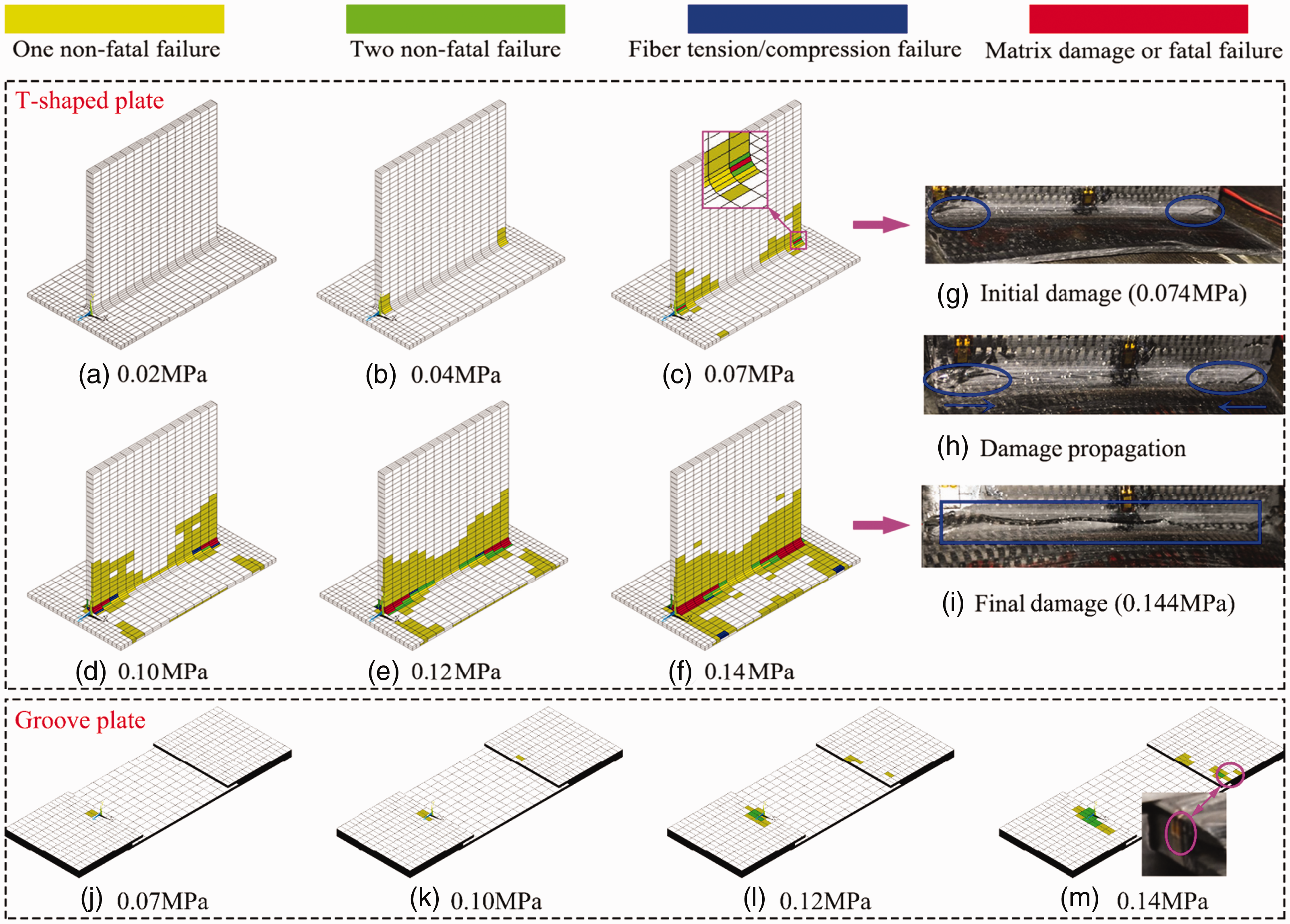
Tensile simulation results and comparison with tests
Comparison of ultimate damage load between simulation and experiment

Figure 8 shows the curves of tensile load and displacement obtained by simulation and experiment. The trends of these two curves are similar, which shows the accuracy of the simulation. However, the experimental load is less than the simulation load as the T-shaped plate may undergo rigid body displacement slightly during the tensile test, which causes the experimental displacement to be greater than the simulation displacement. These two curves both can be divided into two stages, namely damage initiation and damage propagation. First, when the curves arrived at about 4.6 MPa, the root-edge was damaged and the damage would begin to expand after that. Second, when the curves arrived at about 5.6 MPa, the structure was destroyed completely.
The relationship between displacement and load obtained by tensile simulation and experiment.
The tensile failure process of the T-shaped plate obtained by simulation is shown in Figure 9. When the load was 4.6 MPa, each kind of damage mode was found at the root-edge. In the entire loading process, the damage mode of fiber tension/compression failure extended perpendicular to the root-edge to the margin of the flange in the T-shaped plate. However, the damage mode of matrix damage or fatal failure and the damage mode of two non-fatal failures had almost no growth. Moreover, the damage mode of one non-fatal failure extended from the root-edge and formed an annular distribution. When the load was 5.6 MPa, the fiber failure accounted for more than 70%, namely the T-shaped plate was destroyed and the entire structure lost its bearing capacity, which is consistent with the experimental results. Furthermore, as shown in Figure 9(h)–(n), delamination failure extended from the middle of the groove to the groove-edges, which is also consistent with the experimental results. However, the damage concentrated on the diagonal rather than the symmetrical, shown on the surface of the groove plate, because the direction of the uppermost fibers is 45°.
Tensile failure processes of the T-shaped plate and comparisons between simulation and test.
Conclusions
This paper conducted bending tests and tensile tests of a T-shaped hook-connected structure made of 2.5D woven composites (T-shaped plate) and laminated composites (groove plate). Based on the progressive damage theory, a strength prediction method was developed and used to simulate the mechanical behaviors and damage process under bending/tensile loads on web, respectively. Some key conclusions of this work can be summarized as follows.
The maximum error of all results between the tests and simulations is only 9.66%, which proves the accuracy of the simulation results and the rationality of the strength prediction method of progressive damage for the T-shaped hook-connected composite structure proposed in this paper. Whether in the bending test or the tensile test, the initial damages both occur at the root-edge of the web in the T-shaped plate, and then the damages extend to the root-middle in the bending test or extend perpendicular to the root-edge to the margin of the flange in the tensile test. In addition, both in the bending test and the tensile test, the delamination failures are found at the groove-edge of the laminated composite groove plate. It is important to improve the strength of the root-edge of the T-shaped plate and the groove-edge of the groove plate in engineering design.
Footnotes
Declaration of conflicting interests
The authors declared no potential conflicts of interest with respect to the research, authorship and/or publication of this article.
Funding
The authors disclosed receipt of the following financial support for the research, authorship, and/or publication of this article: This work was supported by the Key Laboratory of Aero-engine Thermal Environment and Structure, Ministry of Industry and Information Technology (grant no. XCA1700205).