



Abstract
To realize a one-sided stitching action and stable stitch formation, a poor match between the lead and the hook yarn needles in the stitching process must be avoided as it can lead to hook dropping and hook errors, causing loop loss, thread breaking, and even thread relaxing. Based on an analysis of the principle of one-sided stitching and matching the hook and lead yarn needles, the original stitching technology is improved and a method of trajectory superposition is proposed. A yarn-pulling mechanism is designed for a one-sided stitching device for three-dimensional preformed carbon/carbon composites. By analyzing the principle of the yarn-pulling mechanism, a mathematical model of that mechanism is established, and a trajectory simulation analysis is carried out with MATLAB, which verifies the rationality of the yarn-pulling principle. Results for the two crank angles of the yarn-pulling mechanism and the crank angle of the hook yarn needle at two particular moments reflect the matching relationship of the three, which provides a theoretical reference for the stitching device to adjust to and work well, forming the desired stitch. Finally, stitching tests are carried out, and the test results show the designed yarn-pulling mechanism can cooperate with the hook and the lead yarn needles to complete the stitch lock. This realizes a stable stitching action and avoids hook dropping and hook errors, thereby increasing stitching efficiency.
Keywords
As material science has developed, the advantages of carbon/carbon (C/C) composites in high-technology fields such as the aerospace, automobile, and military industries have become increasingly important. C/C composites are commonly used in aircraft wings, solid rocket motor nozzle throats, nozzle divergent sections, and automotive brake discs for their high strength and light weight. The preforms of these components are usually processed and manufactured by a suture method. Longitudinal fibers can be added between the composite layer fibers during the suture process to enhance the structural properties of the materials, thus improving the damage tolerance of the composite 1 and enhancing the interlaminar shear strength of the composite laminate. Therefore, preformed stitching technology for composite materials has become a key factor affecting the structural properties of such materials. 2 A traditional double-sided stitching technique not only requires setting stitching mechanisms on both sides of the material but also imposes extremely strict requirements on that material, with the technique only applicable to two-dimensional planar materials.3,4 Instead, using one-sided stitching (OSS) technology to stitch composite materials would not only avoid constraining the shape of the stitching object but also enable composite materials to have superior interlayer properties and be strongly tolerant of impact damage.5–9
Europe and America are committed to manufacturing complex structural parts with OSS technology for aircraft,10–12 promoting the development and improvement of stitching equipment. The German company ALTIN Naehtechnik has carried out a series of studies on OSS equipment and technology in which a special stitching head controlled by a mechanical arm is used to produce composite prefabricated parts. 13 The company KSL uses industrial robots combined with OSS technology to manufacture furniture, automobile airbags, and aircraft parts made of carbon-fiber composite materials. 14
In China, Yao and colleagues at Tianjin Polytechnic University are at the forefront of research into OSS technology. They studied a manipulator system and its stitching behavior regarding OSS of composite material, constructed OSS equipment, and conducted stitching experiments. 15 Pan and colleagues at Nanjing University of Aeronautics and Astronautics studied equipment technology for one-sided and double-needle stitching of three-dimensional reinforced composite materials, and verified the stitching performance.16–20 The extended section of a rocket-engine nozzle was stitched by one-sided stitching technology at the Xi’an Aerospace Composite Materials Research Institute. 21 Nevertheless, research in China into OSS technology remains in the exploratory and experimental stage, and there remains some instability in stitching equipment and its action.
In the present study, the research content includes improving the stitching mechanism and adding the yarn-pulling mechanism. The purpose is to avoid hook dropping (when the hook yarn needle (HYN) dose not successfully hook the yarn loop) and wrong hooks (when the HYN incorrectly hooks the yarn loop formed in the previous cycle during the stitching process), improve stitching efficiency, enhance the material’s performance, and promote the development of OSS and its technology.
Improvement of one-sided stitching technology
One-sided double-needle suturing involves two stitching needles cooperating to complete a stitch, as shown in Figure 1.18–20 The yarn is first drawn to the undersurface of the material by the lead yarn needle (LYN) and returns to form a loop under the action of friction. The HYN lags the LYN and descends to the lower surface of the sewing material to hook the yarn loop and bring the yarn back to the upper surface of the sewing material for locking with the ring formed in the previous cycle. The cycle is repeated to form an OSS stitch21–25 as shown in Figure 2.
One-sided stitching (OSS) technology. (1-6) shows the formation process of the stitches during the one-sided stitching process. One-sided stitching (OSS) trace.

In this technology, the needle hook of HYN is placed forward (i.e. in the forward direction of the stitching path), and there is no yarn-pulling mechanism. In suturing, when the yarn loop on the LYN reaches the ideal state, the HYN reaches its lower limit and hooks the yarn loop. In this process, it is easy for the HYN to fail to hook the yarn loop, resulting in hook dropping (a jump stitch); if the HYN successfully picks up the loop, the HYN brings the yarn back to the upper surface of the sewing material and passes through the loop formed in the previous cycle. Throughout this process, because the hook is placed forward (in the direction of the suture path), the HYN is easily hooked to the loop formed in the previous cycle when it moves out of the upper surface of the seam, causing a wrong hook phenomenon. The suturing action cannot be continued, as shown in Figure 3.
(a) Dropped hook and (b) wrong hook.
In the improved stitching technology, the needle hook of HYN is placed backward (in the opposite direction to the stitching path) and the yarn-pulling mechanism added. During sewing, when the yarn loop is initially formed the HYN is inserted into the ring and tightens the yarn. The yarn slides into the hook along the needle rod as the needle moves up after reaching its lower limit. When the HYN brings the yarn back to the upper surface of the sewing material, the yarn-pulling mechanism completes the locking action, as shown in Figure 4.
Process of stitch forming based on improved technology.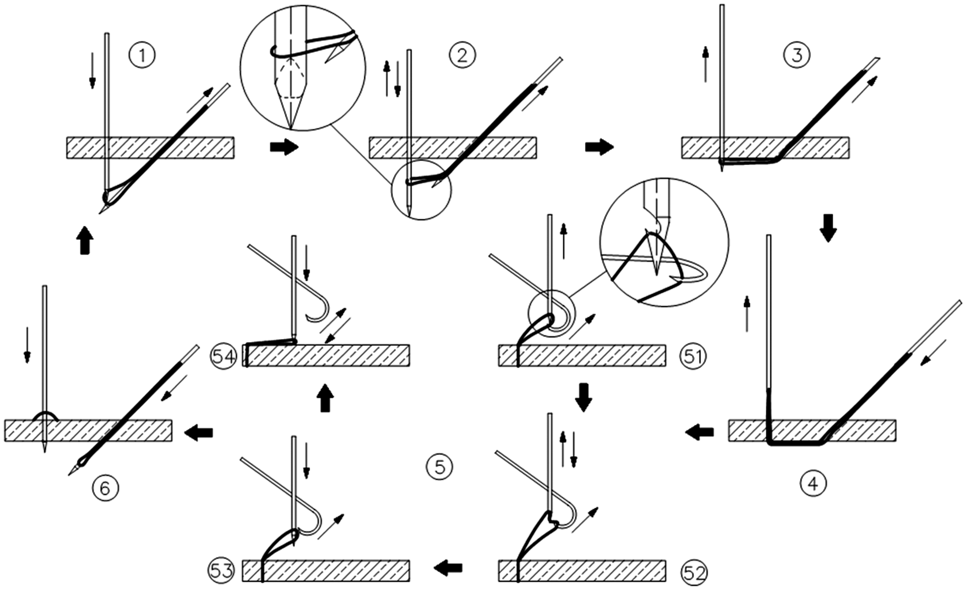
In matching the yarn-pulling hook (YPH) with the HYN, the YPH needs to move the yarn loop from the outer side of the path to the inner side and from the back of the HYN to the front, which requires the YPH to (a) make a swinging motion in the direction from the back and outside of the HYN to the front and inside as the YPH moves, and (b) return around the front and outside of the HYN when the yarn loop is pulled to the appropriate position. Therefore, the motion trajectory of the YPH is selected as an ellipse and placed at an angle to the forward direction of the stitching path, as shown in Figure 5. This type of hook yarn method can avoid dropped and wrong hooks and increase the chance that the HYN hooks the yarn loop successfully and improves stitching efficiency.
Trajectory of the yarn-pulling hook (YPH).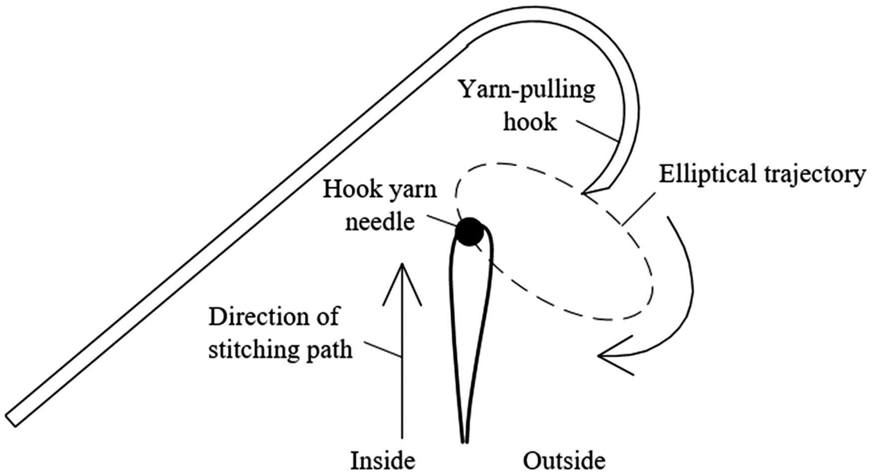
Establishment and analysis of the mathematical model
Method of trajectory superposition
According to the requirements of improved OSS technology, the terminal trajectory of the yarn-pulling mechanism is roughly elliptical when thread pulling. A regular ellipse can be formed by elongating one axis of a regular circle. In forming the trajectory dynamically, the circular and swinging motions are superimposed and the phase between the two motions is adjusted to form the elliptical trajectory required by the yarn-pulling action. Based on the above method of trajectory superposition,26,27 the yarn-pulling mechanism is designed schematically and the associated mechanism diagram is shown in Figure 6.
Schematic of the yarn-pulling mechanism.
The working principle is as follows: the universal joints cooperate with the crank in the global coordinate system to drive the YPH to make a circular motion, and the rocker in the crank rocker mechanism transmits the swing motion to the YPH by the universal joints. Then the circular and swing motions act together on the YPH and make it elliptical.
After selecting the coordinate origin and establishing a coordinate system (Figure 5), the yarn-pulling mechanism of the three-dimensional space can be represented in the two-dimensional space using the equivalent model, as shown in Figure 6. The equivalent simplified model of the yarn-pulling mechanism is shown in Figure 7. According to the requirements of the stitching technology and the cooperative relationship between the YPH and HYN, the long and short axes of the elliptical trajectory parameters can be set preliminarily to d1 and d2. The position and angle of the elliptical trajectory in the coordinates system determined by the coordinates (X, Y) of its center point and the angle Seven-bar yarn-pulling mechanism. Coordinates of elliptical trajectory.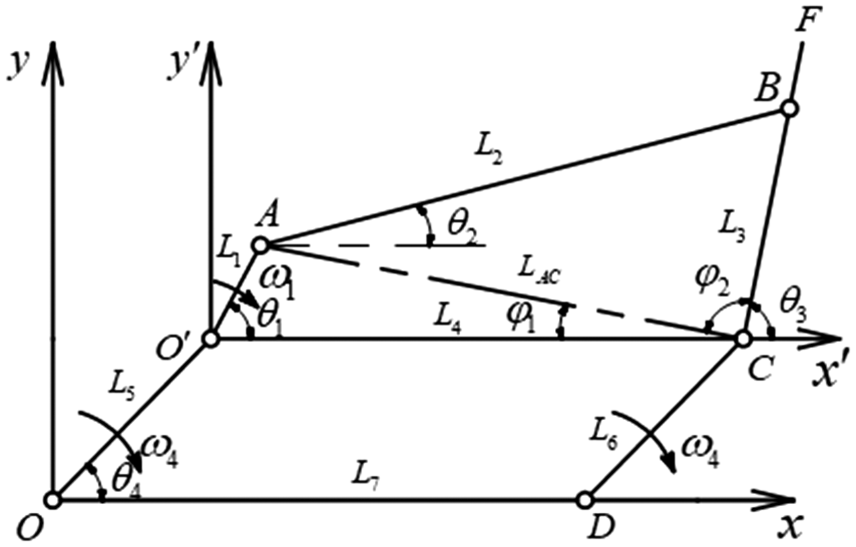

Modeling and analysis of yarn-pulling mechanism
To achieve the superposition of trajectories, the dynamic coordinate system
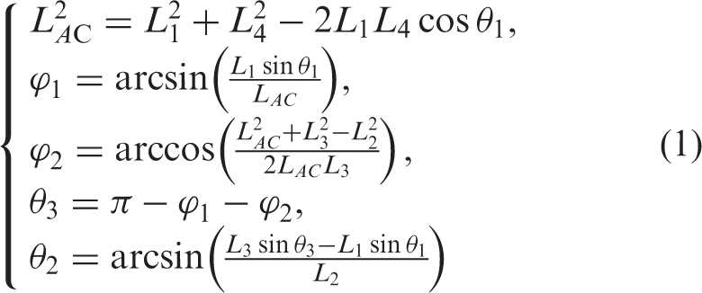

In Eq. (1), suppose that

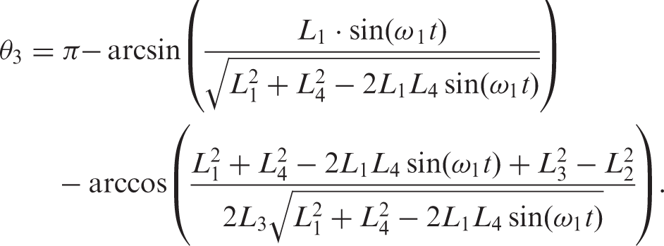
Suppose that


Then the velocity components of the moving point F along the two axes are

Therefore, the speed of point F is


Therefore, the magnitude of the acceleration of point F is

Analysis of matching motion of yarn pulling and HYN
Movement analysis of HYN
In the sewing process, the HYN makes a linear reciprocating movement in a vertical direction. The thread loop is hooked from the lower surface of the sewing material to the upper surface, then works with the YPH to complete the thread stitch lock. Therefore, the HYN is driven by a sliding-rod crank mechanism as shown in Figure 9.
Sliding-rod crank mechanism of the hook yarn needle (HYN).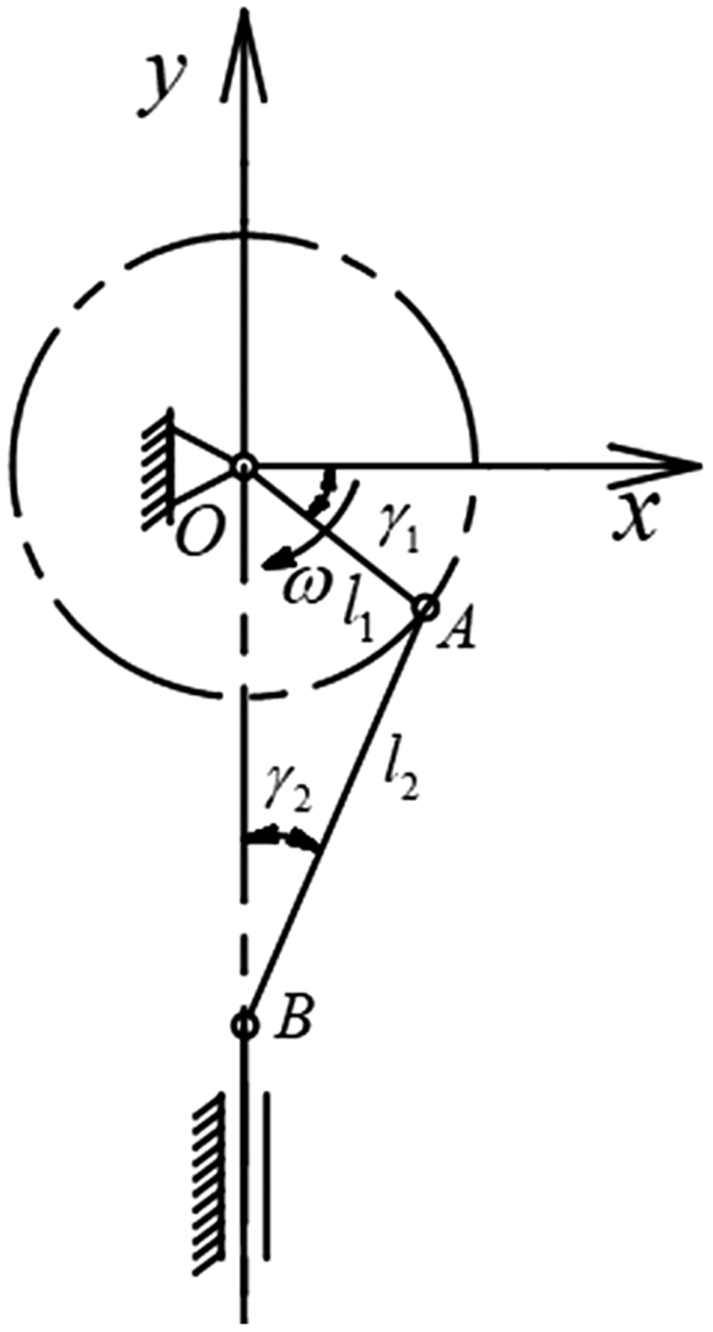
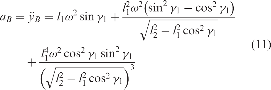
The displacement of point B during the movement of the crank and slide bar mechanism is
4


Analysis of the yarn-pulling mechanism
In the process of stitching, the tip of the YPH moves elliptically on the horizontal plane whereas the HYN performs a straight reciprocating motion in a vertical direction. During this motion, the YPH should first press then pull the yarn loop from the back and outside of the HYN to the front and inside. When the yarn loop reaches the ideal position, the YPH should return around the front and outside of the HYN to avoid yarn slack caused by the yarn-pulling route being too long. A hooking yarn diagram of HYN is shown in Figure 10. The distance between the bottom of the hook and the tip of the needle is labeled A and the yarn pressing should be completed when the distance, l, between the bottom of the hook and the plane of the YPH is approximately a/2. At this time, the distance between the tip of the YPH and the axis of the HYN is set as x, and yarn pulling should be completed when the point of the hook needle is higher than the elliptical plane. Therefore, the optimal timing for cooperation between the two needles should be found.
The yarn-pulling hook (YPH) is matched with hook yarn needle (HYN). In the figure, the four planes are: 1) the plane of the bottom of the needle hook when the HYN reaches its upper limit position, 2) the plane of the needle tip when the HYN is at its upper limit position, 3) the upper part of the YPH section, and 4) the plane of the axis of the YPH, and the position of the HYN indicated by the broken line is its upper limit position.
According to the experimental analysis, for the matching position the difference between the height of the pulling hook in the plane and the height of the hook needle tip when it reaches the upper limit should be greater than the radius of the cutting interface of the pulling hook, namely Angle of the yarn-pulling hook (YPH).

In conclusion, point A can be regarded as the starting point for matching the YPH and HYN when the yarn-pulling mechanism pulls the yarn. At this time, the distance of the HYN from its upper limiting position is
Example analysis and trajectory simulation
Parameter calculation and trajectory simulation of the yarn-pulling mechanism
According to the requirements of the improved stitching technology, when the long axis of the elliptical trajectory is d1 = 15 mm and the short axis is d2 = 8 mm, it can meet the requirements of the yarn-pulling motion trajectory. The short-axis trajectory is completed by the double crank mechanism, so the double crank length is 8 mm, namely L5 = L6 = 8 mm. The crank angle between the extreme of the crank and the rocker mechanism is β as shown in Figure 12.
Extreme angular position of crank and rocker mechanism.
The length of rod l




Solving Eqs. (13)–(16) gives O′A = 1 mm and AB = 91.5 mm. Because of the requirements of the yarn-pulling technology, the yarn-pulling action is stable and reliable, and the yarn-pulling mechanism needs the same time to hook and exit the yarn loop in yarn pulling. Therefore, the crank and rocker mechanism is required to have no obvious quick-return characteristics. The angle
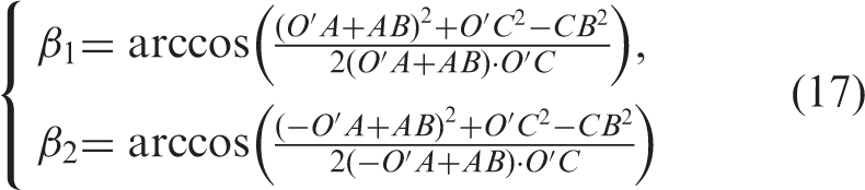
Solving Eq. (17) gives β = 0.357° and K = 1.004, where K is the coefficient of travel speed variation and is approximately the same. There is no obvious quick-return characteristic that meets the technology requirements.
Equation (2) gives the coordinates of the elliptical trajectory point of the dialing yarn, and all the parameters of the yarn-pulling mechanism have been determined. The speed and acceleration of the elliptical track can be found from Eqs. (6) and (8), and the parameters are determined and substituted into MATLAB for simulation, as shown in Figure 13. It can be seen from the variation curve that the trend in the elliptical trajectory velocity and acceleration is continuous without abrupt changes.
Change curves of velocity and acceleration of yarn-pulling trajectory with the crank angle.
To ensure the YPH can take the yarn loop successfully, the center coordinate of the elliptical track in the static coordinate system Elliptical trajectories of terminal of yarn-pulling mechanism for different values of Parameters of ellipse for different values of 

So, taking points on the trajectory when 
Example analysis of matching of the yarn-pulling mechanism and HYN
According to the original design of the mechanism, the values of the various dimensions in the motion of the hook yarn are a = 3 mm, d = 2 mm, h = 2 mm, and H = 60 mm, from which we have α = 33°. According to Eq. (18) for the ellipse and the working angle α of the YPH, the coordinates of starting point A, where the YPH and HYN are matched, are obtained as (69.8, 96.36).
The displacement, velocity, and acceleration of the HYN can be found from Eqs. (9)–(11). According to the design requirements, the lengths of the rods in the hook yarn mechanism are l1 = 30 mm and l2 = 80 mm, and the crank speed is Change curves of velocity and acceleration of the hook yarn needle (HYN).
The matching height of the HYN is determined by its crank angle Displacement of hook yarn needle (HYN) in z direction and displacement of yarn-pulling trajectory in x and y directions.
As can be seen from the displacement relationships in Figure 15, the HYN can be matched precisely with the YPH at point A when
Stitching test
In the stitching technology used before improvement, the yarn is broken if the HYN drops or makes a wrong hook and stitching cannot be continued; the defect shown in Figure 17 will appear.
The breakage of yarn caused by a dropped or wrong hook.
In this paper, to verify the accuracy of the theoretical analysis and ensure a stable stitching action can be carried out, an OSS device based on improved technology was designed and constructed according to the above analysis. The device was adjusted according to the calculation results and used to carry out stitching tests in which carbon-fiber yarn was selected to stitch a 25 mm-thick laminated carbon cloth. The yarn-pulling process of the YPH in the test is shown in Figure 18.
Process of the yarn-pulling mechanism: (a) pushing the yarn; (b) pulling the yarn; (c) return around the hook yarn needle (HYN).
Figure 18(a) shows the process by which the YPH presses the outer yarn loop, (b) shows the YPH pulls the loop from the outside of the HYN to the inner side when the HYN descends, and (c) shows the YPH makes a return movement around the HYN, then the HYN passes through the loop and pierces the seam for the next cycle of stitching.
To verify the yarn-pulling mechanism can cooperate successfully with the HYN to pull the yarn loop without hook dropping or errors and complete the stitching action smoothly, five stitching tests were conducted on laminated carbon cloth using the OSS device (with 20 needles per stitching). The stitching patterns of the stitched yarn are shown in Figure 19. During the stitching process, the working stability of the yarn-pulling mechanism is evaluated by observing the successful rate of the YPH pulling the yarn loop; test data are shown in Table 2.
Stitching patterns: (a) upper surface of seam; (b) underside of seam. Successful yarn-pulling rate of the yarn-pulling mechanism in stitching tests

The data in Table 2 show the yarn loop was pulled successfully in the five stitching tests, comprising 100 occasions of yarn loop pulling. The tests show the yarn-pulling mechanism is based on correct principles, operates stably, and successfully avoids hook dropping and errors, thus improving the stitching efficiency and achieving the stated goal.
Conclusion
Aimed at solving the problems of yarn slack and yarn breaking caused by dropping and wrong hooks with a traditional stitching mechanism in the stitching process, in this paper the original stitching technology was analyzed and improved, the principle of forming a stitching trace was analyzed according to the improved stitching technology, and the motion trajectory of the yarn-pulling mechanism was established. The idea of trajectory superposition was then proposed according to the principle of forming the motion trajectory, and a yarn-pulling mechanism suitable for carbon-fiber yarn stitching was designed. In the stitching process, the yarn-pulling mechanism should work with the LYN and HYN, and the best matched position and time between the yarn-pulling mechanism and the HYN were derived via the analyzed and calculated coordinate motion of the three (the LYN, HYN, and yarn-pulling mechanism). The phase difference (
Footnotes
Acknowledgements
The authors gratefully acknowledge the support from Tianjin Science and Technology Committee towards this study.
Declaration of conflicting interests
The authors declared no potential conflicts of interest with respect to the research, authorship, and/or publication of this article.
Funding
The author(s) disclosed receipt of the following financial support for the research, authorship, and/or publication of this article: This work is supported by the key technologies R&D program of Tianjin (Grant No. 15ZCZDGX00840).
