




Abstract
The latest progress in the emerging wireless technology has resulted in the development of wearable antennas made of various fabrics. This unique antenna is an integral part of the wireless body area network (WBAN). A wide range of applications are made by the wearable antennas in the fields of the Internet of Things, sport, defense, public safety, telemedicine, navigation, and tracking. The focus point of the current review is the recent progress of electro-textiles research with special attention on the materials properties, criteria, and manufacturing techniques. Existing as well as upcoming materials specifically and potentially used for electro-textile fabrication are discussed. Various manufacturing techniques are discussed to match the importance of material selection. The current work highlights the performance when the antennas tagging are applied in WBAN objects and illustrates how the human body affects the performance of the wearable antenna and vice versa. The findings of this review by introducing the best materials, techniques, and designs could be used in future to provide high-performance materials for body-centric applications.
Keywords
The prevalent enhanced and escalating interest in combining added multitudinous clothing functions has resulted in a comprehensive array of wireless body area network (WBAN) applications.1,2 Wearable antennas were first adopted for home-nursing, hospital patients' clothing, and rescue workers' clothes. Aside from their utilization capabilities as depicted in science fiction, wearable antennas are also used in healthcare sectors and security agencies, such as firefighters and the police. 3 Some of the famous sports clothing manufacturers, such as Nike, Adidas, and Li Ning, have started providing various smart wearable clothes. Therefore, different sports shoes, such as the HyperAdapt series, and clothes, such as the Hyperdunk series from Nike, are under development with additional functions of wireless communications. Sports detecting chips, wireless transmissions, and embedded data analysis are considered by Li Ning to enable smart sports.4,5 The Global Positioning System (GPS) and maps are used for positioning and navigation, and pressure and temperature sensors are mounted in different sport applications. 6
A health management system that can deliver necessary data to users, such as fitness and biomedical data, is very much needed. In addition, for those who exercise, seniors included, a tool that would provide instant feedback of the user's body condition could also be a lifesaver to prevent sudden cardiac arrest. The use of GPS coordinate tracking for the emergency response team will decrease the response time.7,8
The eminence of wearable antennas has played a consequential part in the formation of a wireless-connection link between the material worn on the body and the encompassing matrix, which is both stable and effective. Due to the intensified concerns that have built-up in recent times pertaining to antennas and the generation of research in this particular field related to body communication systems, the IEEE 802.15 standardization group was formed. Its intent is to standardize off-body, on-body, and in-body communication applications. The wearable antenna will be very near in terms of its proximity to the human body. Thus, it is of the utmost importance that the conductive fabric materials should demonstrate adequate properties that are conducive as an antenna radiating component or as a ground plane. 9 Important antenna-to-body isolation is provided by a proper and efficient ground plane, which also protects the antenna performance from the body effects. At the ultra-high frequency (UHF), the human body cannot be penetrated by electromagnetic (EM) waves. Communications that are centered toward the body have been a rampant manifestation in body area networks (BANs) and personal area networks. 10
It is the prevalent norm that most wearable antennas are comprised of flexible conductive materials that provide ease of integration into garments. 11 These conductive materials are known as electro-textiles; they include embroidery structures generated from commercially available conductive fabrics and conductive threads. The most common form of electro-textile is a dielectric substrate with a microstrip antenna on one side of the substrate and a ground plane on the other. These characteristics are considered for appropriate in body-worn applications as a result of the radiation emitted is perpendicular to the linear structure and the ground plane. This functions as an effective protective shield for human body tissues. It posits numerous advantages, such as light weight, low cost, low volume, almost zero installation maintenance, and low profile planar configuration. Thus, it is extremely favorable and suitable to be integrated into clothing.
It is advisable that other factors be discerned with care in ensuring secured antenna performance in the body-worn environment, irrespective of the measurements, such as radiation pattern, efficiency, and return loss and gain (utilized in the customary tag). It is important for those who are involved in designing textile antenna materials to possess the know-how pertaining to EM properties in terms of permittivity and the loss tangent of the textile. In the making of substrates, the utilization of Zelt, pure copper and Flectron, silver-plated copper or nylon, and other varieties of conductors are the constituents of the radiating elements. Meanwhile, the utilization of silk, Quartzel, fleece, polyester, and fleet as substrates are the constituents in the production of non-conductive fabrics. 12
The current work aims to present the latest wearable textile antenna varieties. It is necessary that certain conditions and concerns be examined, encompassing the choice of an appropriate material, the methods of manufacturing, and analysis needed for the wearable antenna design. Also, the different application areas for wearable devices are described in the literature.
Features of textile materials
A flat and linear structure with the incorporation of flexible versatile construction materials is needed in the making of wearable antennas. Various properties of the materials have a consequential impact on the behavior of an antenna. For example, in the determination of a planar microstrip antenna efficiency, the permittivity and thickness of the substrate are both utilized. The characterization of textile properties is required in the production of wearable antennas. Certain particular electrically conductive textiles can be found on the market and they have been used successfully. For substrates, ordinary non-conductive fabrics have been used.
Nevertheless, the information on EM properties of normal textiles that has been garnered are meager. Thus, the current paper focuses primarily on the analysis of dielectric properties for normal fabrics. In general, textiles produce a very low dielectric constant, which enhances the antenna's bandwidth and electrical resistance. This, in turn, decreases the surface wave losses. Nevertheless, there is a continuous exchange of water molecules contained in the textile materials with the surroundings, which impacts the EM properties. Moreover, the low pressures of the textile fabrics, which are compressible, porous, and anisotropic, have the ability to change the density and thickness of these materials. The knowledge of the impact of these characteristics that minimize unwanted effects on tag behavior is indeed important. 13
The complex value parameter
Dielectric constant and loss tangent of different fabrics
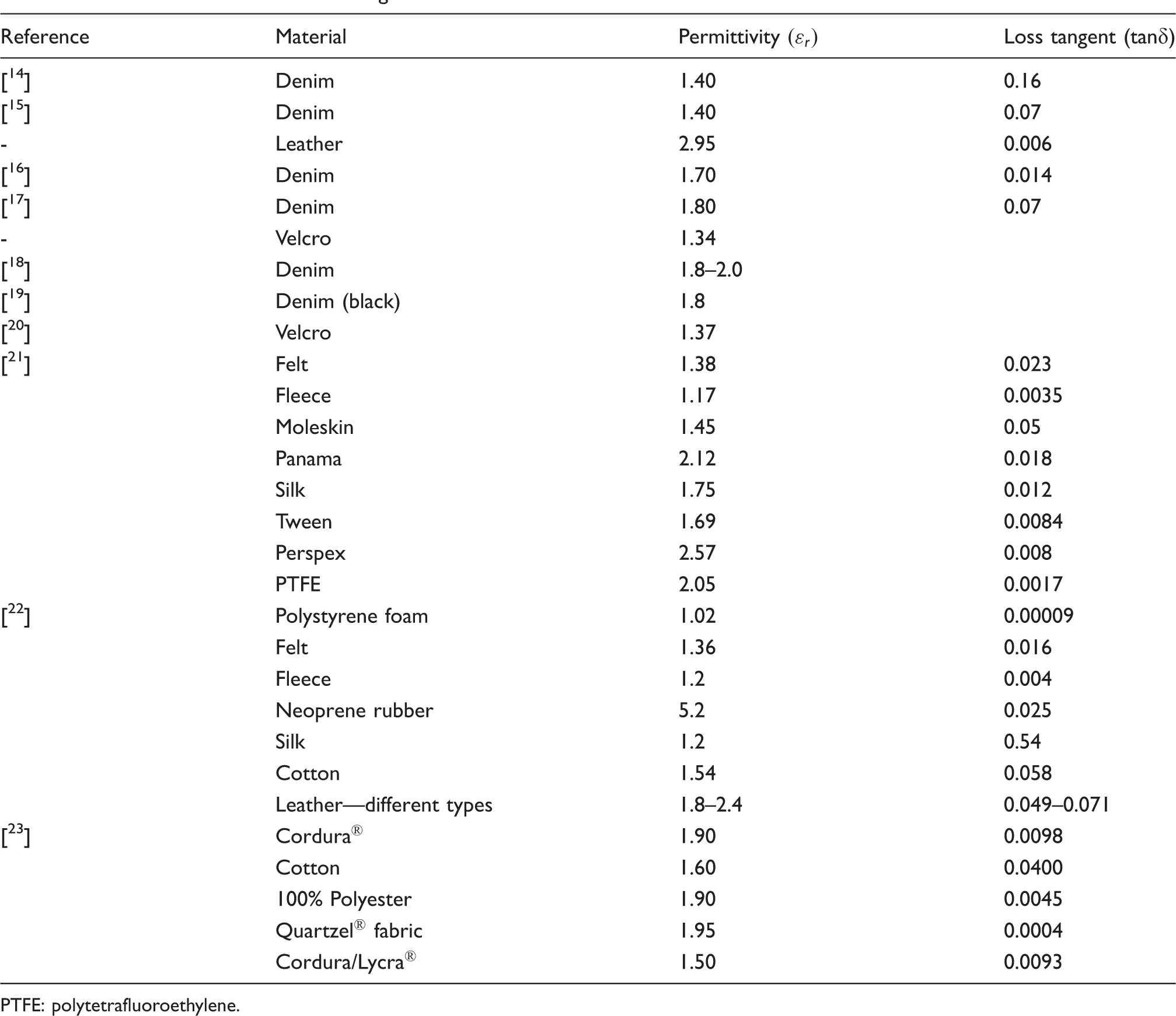
PTFE: polytetrafluoroethylene.
Linear plane materials are conductive fabric materials that possess surfaces that are electrically resistant. The electrical conductivity behavior of these materials could be calculated by using surface resistivity characterization and resistance. The relevant parameter in antenna design is its conductivity when using fabric material, in which σ represents surface resistivity with the unit in Siemens per meter (S/m), whereas ρ
s
is the density and t the thickness of the fabric: metal particles or carbon, which are filled with fibers; the fibers are plated with metal or conductive polymers; the use of conductive material fibers.
Individual or numerous fibrils of non-conductive and conductive fibers from conductive threads are involved in the process. As shown in Figure 1, conductive threads fall into two categories: multi-filament threads (see Figures 1(a)–(d)) and monofilament threads (see Figure 1(e)).
23
The electrical reliability and wearability characteristics of each are different. Figure 1(e) illustrates the monofilament conductive thread, which comprises an individual silver-plated copper fiber of diameter 40 µm. In addition, the fabrication of the X-static thread (Figure 1(a), Sauquoit Industries Inc., Scranton, PA) is via the twinning of multitudinous narrow elastic silver-plated nylon threads. Furthermore, the Litz wire (see Figure 1(b)) constitutes of 60 copper fibers of 40 µm diameter each. The strands of threads in Figures 1(c) and (d) are complex threads composed of metallic and insulating fibers.
23
Various conductive threads.
23
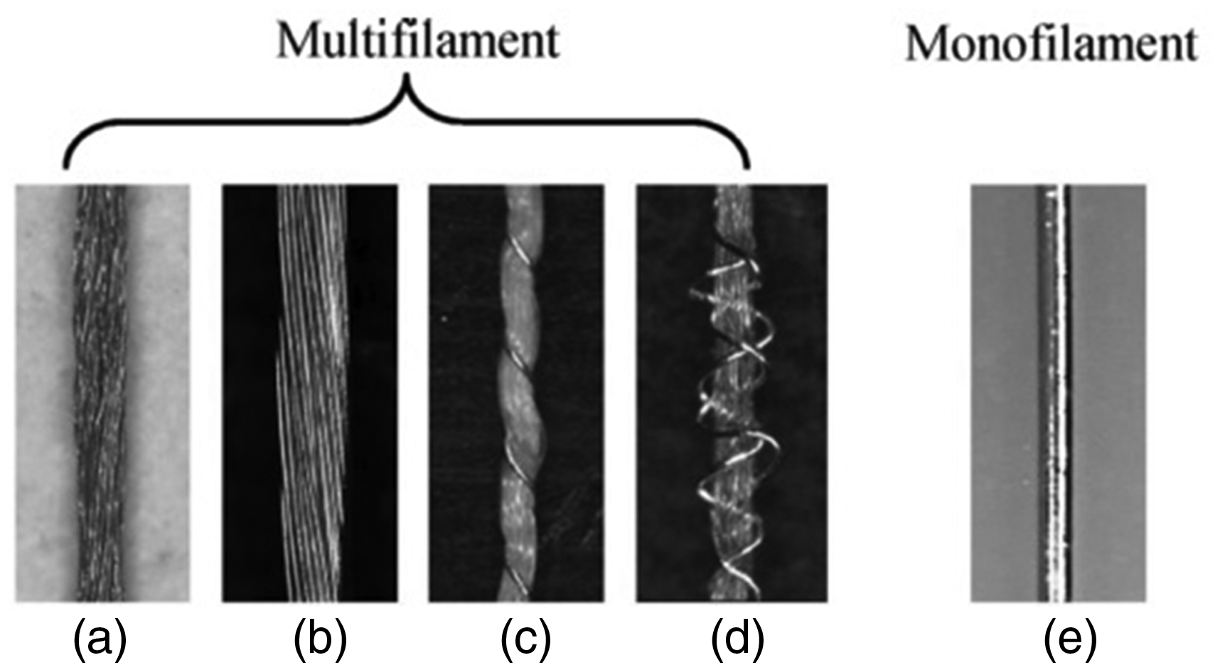
A non-conductive center comprising various non-conductive fibers consisting of 40 µm silver-plated copper fibers twirled around the core formed both of the complex composite threads. Thus, the fragility of the thin conductive fibers is shielded against the exterior tension by the strong non-conductive fibers. This resulted in enhanced sturdy and tough conductive threads, while concurrently sustaining electrical performance. 23 The enabling of conductive thread to become elastic via the utilization of elastic non-conductive core, as in Figure 1(d), fulfilled the coveted wearability characteristic and at the same time enabled the fabric to have the quality of a conventional material.
It is common enough that electro-textiles are formed by integrating conductive threads into fabric materials through knitting and weaving techniques. The choice of both conductive threads ascertains the efficient performance of the textile in terms of its strength and equivalence as an electroconductive material. In the case of knitted fabrics, the threads interloop through each other, resulting in interlocking loops. Meanwhile, in the case of woven fabrics, the threads are aligned in straight lines, and are found to be in two orthogonal orientations. Customarily, in woven fabrics, conductive threads are utilized in both directions. Syscom Advanced Materials 29 comprise silver-coated nylon fibers (Agsis™) and thin silver-coated copper fibers (LIBERATOR ™ 40). The metal monofilaments are sourced from the Swiss company Elektrisola Feindraht AG (Escholzmatt, Switzerland), which produces the filaments. It is mixable and can be integrated into various kinds of fibers or utilized on its own into the knitted and woven fabric material. Significantly, there arise various possible electrical characteristics in accordance with the materials utilized in the making of the fabric material. The materials encompass a wide array of elements ranging from brass (Ms) filaments to copper-clad aluminum (CCA) filaments, copper (Cu) and silver-plated copper (Cu/Ag) filaments, silver-plated brass (Ms/Ag) filaments, and aluminum (Al). 30 The Swiss-Shield® (Flums, Switzerland) company has a niche of its own and specializes in the creation of metal monofilaments. These are integrated into the base yarns, such as polyamides, polyester, aramids, and cotton. As an example, the metal monofilaments were composed of bronze, aluminum, gold, silver, copper, and brass.
Electrical properties of metal monofilamentsa and multi-filamentb threads

*German Milbe denomination, where “M” is accompanied by a number stating the composition in %Cu with respect to a Zn complement to 100%.
In summary, the choice of conductive threads has a great impact on the effectiveness of conductivity in relation to the density of the thread by scrutinizing the difference in magnitude orders. In achieving optimal efficient conductivity, the most favorable choice in this test set is the monofilament silver-plated copper, as the efficiency in conductivity results in the minimization of conductive loss of transmission lines, antennas, and electro-textile resonators inclusive of any other microwave devices possessing linear plane compositions.
Manufacturing techniques
The method of processing these smart materials into textile materials should be considered. Different technologies are used to incorporate these smart materials into a textile structure. Listed are the manufacturing techniques classifications of textile antennas.
The conductive textile can be used as yarns to knit or weave the antenna conductive patterns and be stitched together with the non-conductive textile substrate. Flexible textile antennas can be produced as uniform and thin metallization layers. This can be achieved by affixing non-conductive clothing material to elements such as foil, silver tape, or copper. Production of conductive patterns using embroidery made from conductive textile yarns on the non-conductive textile substrate. The printing of non-conductive textile fabrics by using screen and inkjet printing.
32
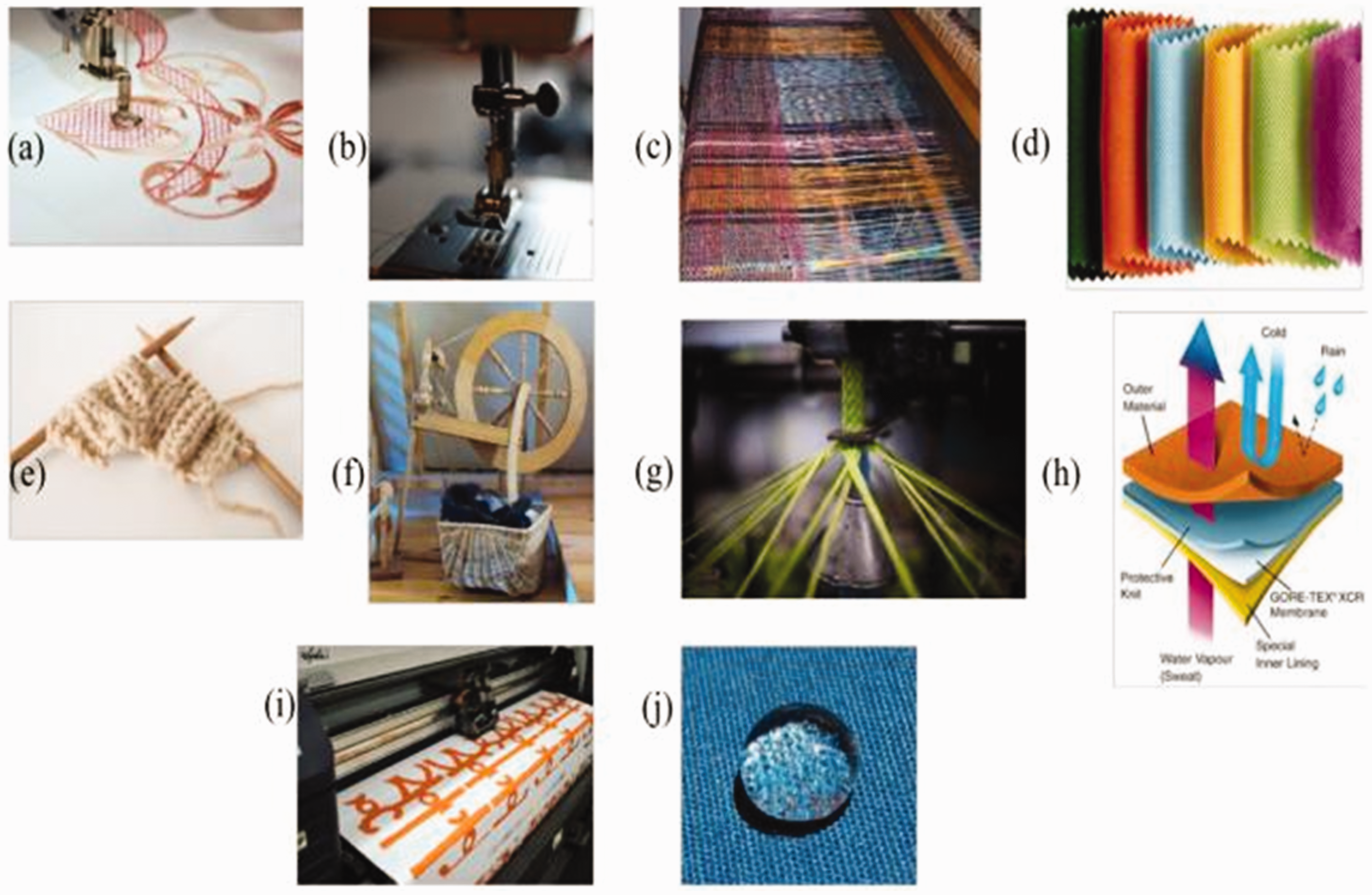
There are various kinds of textile/fabric manufacturing: (a) embroidered fabric material
33
; (b) sewn textile materials
34
; (c) woven fabrics
35
; (d) materials that are not woven
36
; (e) knitted fabrics
37
; (f) spun fabrics
38
; (g) braiding
39
; (h) coated fabrics through/lamination
40
; (i) printed fabrics; and (j) chemically treated fabrics, as studied by Stoppa and Chiolerio.
32
With the aid of different technologies, Figure 2 shows the incorporation of elements into the fabric composition.
Various types of fabric material manufacturing and treatment: (a) embroidered fabric material; (b) sewn textile materials; (c) woven fabrics; (d) materials that are not woven; (e) knitted fabrics; (f) spun fabrics; (g) braiding; (h) coated fabrics through/lamination; (i) printed fabrics; (j) chemically treated fabrics.
32
A plethora of source materials has resulted in a wide array of fabrics. However, it is common that commercialization has resulted in attire consisting of conventional cables, electronic parts that are in miniature sizes, and special connectors. It is human nature that comfortable fabrics are favored as choice over hard, stiff fabrics. There were initial endeavors to utilize the fabrics in terms of their electronic performances. 32 An easy fabrication technique can be seen in the embroidery technique, which utilizes conductive yarns. Its utilization has been practiced on wearable antenna fabrication applied to a variety of textile materials. 41 Furthermore, sewn textile materials through the sewing technique is a potential technique used to embed electrical connections in fabric materials. 42 In terms of sewing technique, a folded dipole was sewn with conductive threads on the fabric, where beneath this fabric, buckram fabric was used to strengthen the substrate during the operation of sewing. 26
Traditionally, embroidery is patterned aesthetic shapes created from colored threads based on processes using textile material. A similar process could be adopted in producing antennas by using conducting threads instead of the conventional thread for the embroidery on the base textile. Meanwhile, the process of ‘embroidering’ is a more variable and flexible manufacturing process. Any typical fabric can be embroidered with conductive threads to produce the required linear (planar) conductive composition. Furthermore, a mesh of conductive threads can be utilized to simulate metallic wires and plates compositions that shape a traditional antenna. 43 Since embroidery machines are already in existence in the industry, there is no need to create something new or use something that is not currently available. Hence, this is an added edge over another choice as there is the ease of process application. The production of clothing en masse, which is integrated with embroidered textile antennas, is seamless.
It is more conducive for the process to adopt a technique that applies current to flow along the threads, and these techniques are favorable in embroidered antennas compared with techniques that employ current flowing from thread to thread. Thus, the embroidery technique leans more toward linear antennas, such as dipoles or spirals. These particular compositions can be problematic in terms of fabrication when utilizing copper tape or Nora Dell cloths. Furthermore, another advantage in using dipoles or spirals as opposed to patch antennas is in terms of its design, which results in the decrease in thread length and consequentially a reduction in antenna cost. It should be noted though that special threads are utilized in the process of embroidery; the constituent of these threads consists of silver, which is a costly metal. It should also be noted that a similar case occurs in Nora Dell and inkjet printing. Hence, the amount of wastage due to the use of manufacturing techniques has a huge impact on the costs of manufacturing.
44
Through the designing of wearable textile antennas, beautiful and compact designs could be attained. Nevertheless, there is a restriction on the accuracy of embroidery, which is limited to an estimated one millimeter.
44
This limitation can be partly solved through the utilization of computer-aided embroidery. In addition, the attachment of the textile layers together does not necessitate the use of glue with embroidery.
45
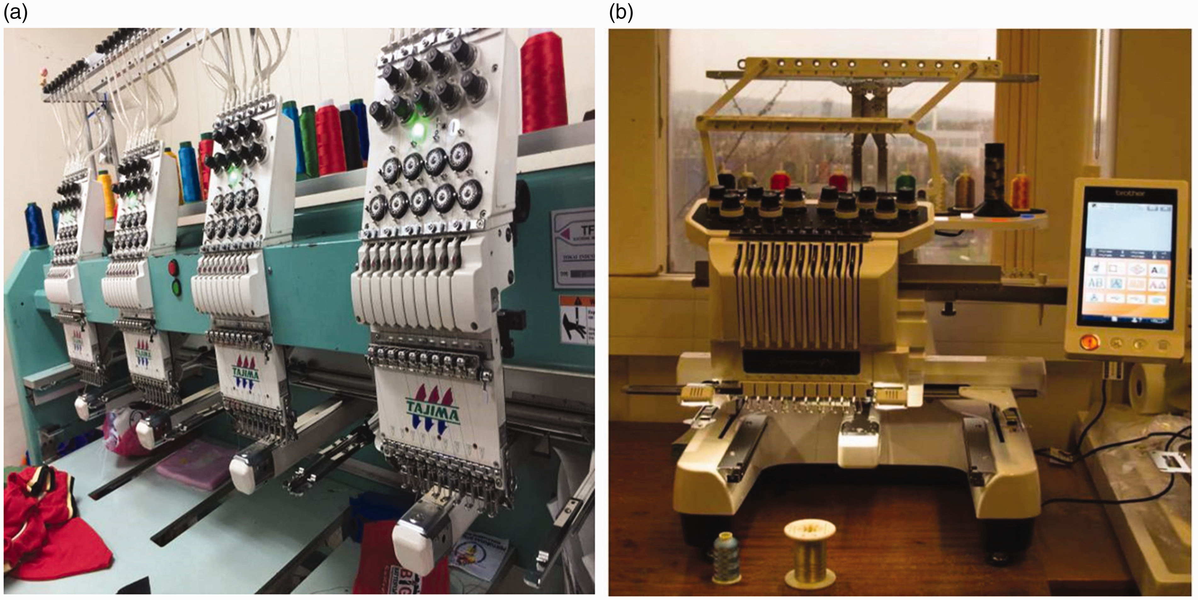
The wash-ability of the garment is enhanced by the incorporation of the integrated antenna. Although the process of embroidery remains the same, advancement in technology has enhanced the process further by enabling digital images to be embroidered directly onto the fabric through the use of a computer-aided embroidery machine (Figure 3).
(a) Tajima Neo Industrial Embroidery Machine. (b) An embroidery machine that is aided by computer, at Loughborough University.
44
Wearable electro-textile design
This section concentrates on the developments in the field of smart textiles, which gives careful consideration to the flexibility, technique, stability, and size in human body issues. It also reviews the various types and designs of electro-textile tag antennas in WBANs that have been proposed recently. Virkki et al.
46
indicated that the interconnections between the conductor walls that serve as the ground plane and radiating patch in a slotted patch antenna are stitched with a conductive yarn. An embroidered interconnection was proposed between the radio frequency identification (RFID) microchip fixture and the electro-textile. In addition, the EM optimization process and platform-tolerance were outlined for the antenna in a body-worn configuration and the measurement of the on-body performance was investigated considering various parts of the human body. A conductor in the antenna is shown in Figure 4(a); it is made from nickel and copper-plated Less EMF Shieldit Super Fabric (Cat. #A1220) and, as a substrate EPDM (ethylene-propylene-diene-monomer) cell, foam of 4 mm thickness is used.
46
(a) Structural feature of a slotted patch antenna with dimensions (mm). (b) Samples of the manufactured electro-textile and copper tape tags with dimensions L1 = 64, L2 = 13.6, W = 33.5, a = 2, B = 5, c = 4.75, and D = 31.1.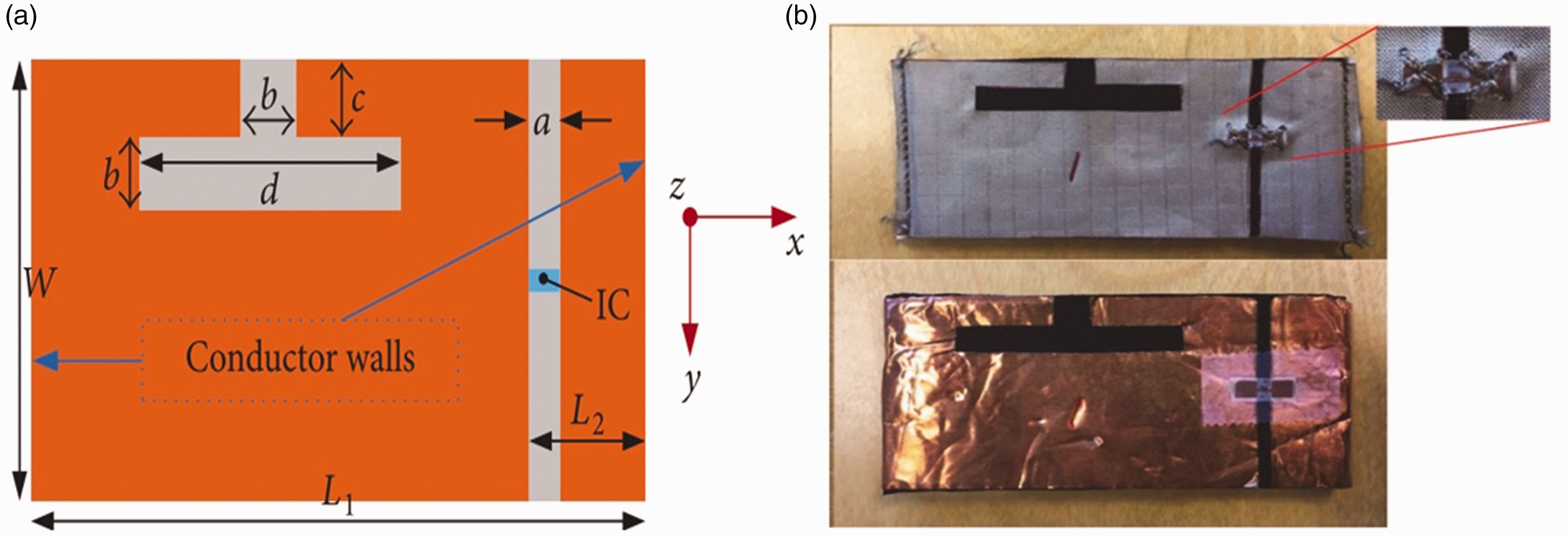
The electro-textile versions and copper tape of the tag were fabricated for testing; the antenna shape for the copper tag was shaped from the copper tape as an individual piece by using scissors and was bent over the borders of the EPDM substrate to be shaped as an antenna and the walls of the entire construction
46
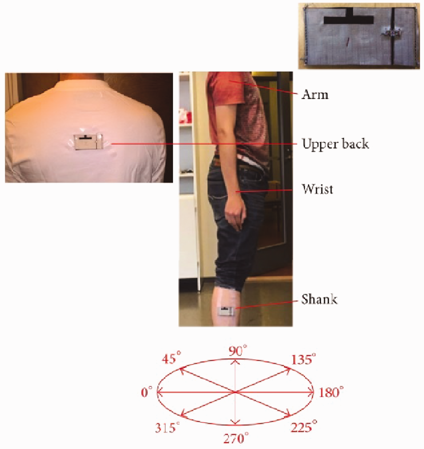
(Figure 4(b)). Via this method, conventional textile processing has been used to embed tags that can be worn and other instruments and gadgets, which includes electro-textile interfaces (Figure 5). Calculated results indicate that a conventional electronics manufacturing methodology founded on the proposed textile manufacturing approach using a copper conductor can produced attainable tag reading with ranges of 3–4 and 6–7 meters, respectively, in various common body-worn configuration situations.
Measurement setup used in the testing of the tags in body-worn configurations.
46
Ginestet et al.
24
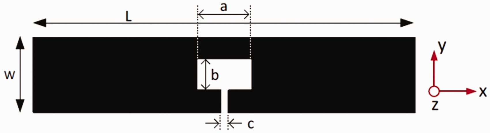
investigated a dipole integrated inductive matching loop and a UHF RFID tag antenna and proposed a cost- and time-saving novelty through embroidering on the antenna borderlines, as depicted in Figure 6. Previously, a study on the effect of a sewing pattern and material saving in embroidered antennas was conducted to determine the tag performance.43,47
The geometry of the antenna (mm), where L = 100, W = 20, a = 14.3, b = 8.125, and c = 2.
24
The antennas were produced using five different patterns, as shown in Figure 7. An NXP UCODE G2iL series IC was used as the tag Integrated Circuit (IC). The nearness of the human body to the material is the basic problem in wearable electronics. The high dielectric constants and energy emitted by the human tissues restrict the effectiveness of antenna radiation. It basically changes impedance when differentiated with free-space.
The radio frequency identification (RFID) tags: (a) copper tape tag with a glued IC; (b) copper tape contour (1 mm) tag with a glued IC; (c) copper electro-textile tag with an embroidered IC; (d) nickel/copper electro-textile tag with an embroidered IC; (e) embroidered contour tag with an embroidered IC; (f) embroidered contour tag with IC embroidered together with the antenna. IC: Integrated Circuit.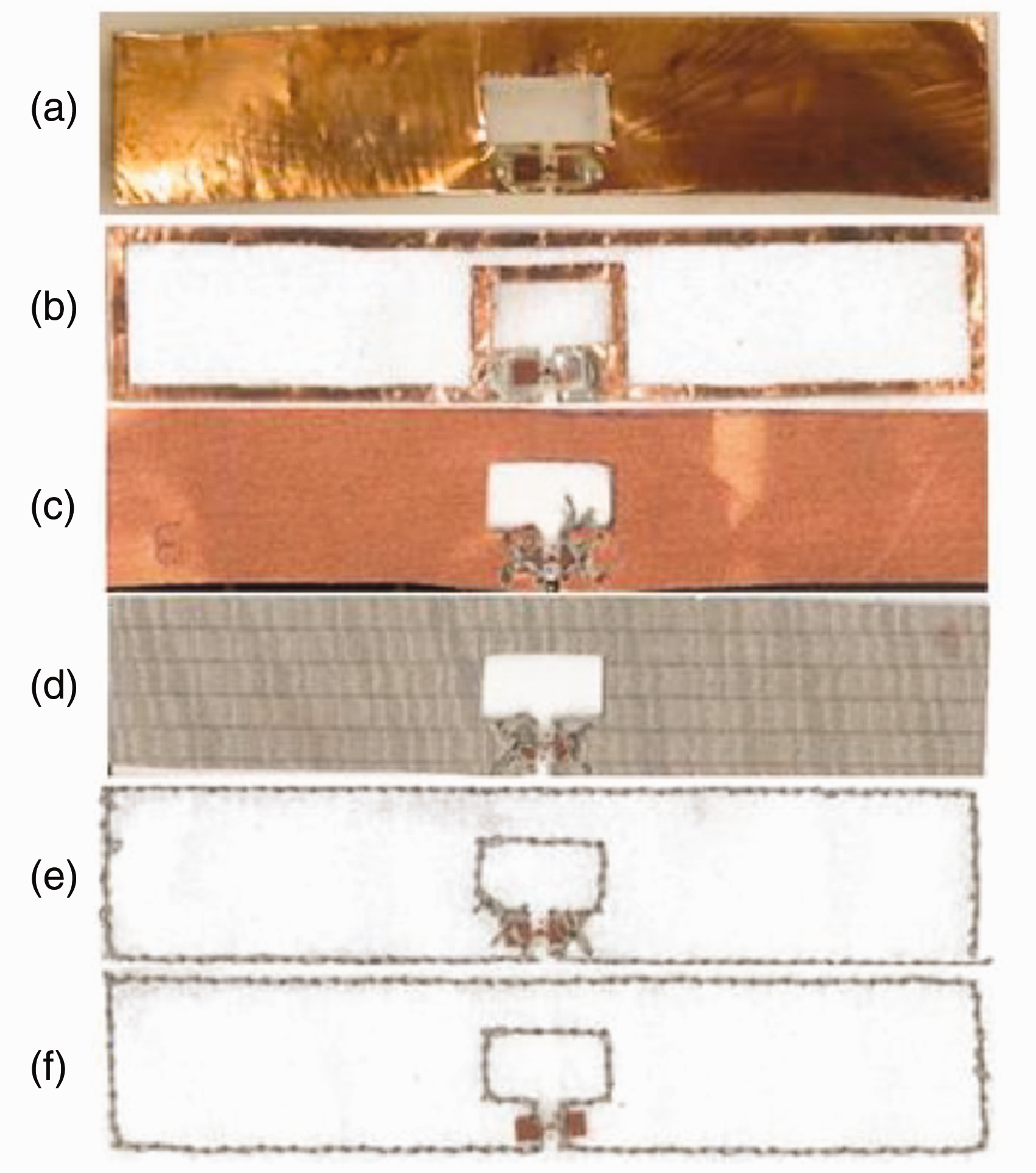
However, this work has set limitations and boundaries to the scope of the investigations in terms of the assessment of the ways in which innovative manufacturing methods impact the performance of the EM performance of textile tags. Hence, due to the interference of human body emissions, the measurements of the tags in terms of body-worn configurations are not considered. The tag and the surrounding air configuration is measured to eliminate additional ambiguity sources.
The passive UHF RFID electro-textile tags are interconnected with the embroidered IC chip. There are prospects in creating a planar dipole antenna by limiting the embroidery work to the edges of the full antenna shape. The results show similar or excellent tag performances via the embroidered interconnections in differentiating and examining it against identical antennas that have microchip ICs affixed with conductive adhesive.
Similarly, from the measurement results, tags with antennas formed on the borderlines demonstrated outstanding wireless performance. This demonstrates that by utilizing this technique, the consumption of conductive materials and time would be reduced.
24
The inaugural design guideline proposal pertaining to a flexible and fully wearable embroidered RFID patch antenna that utilizes the tag antenna design concept has been put forward.2,28 The execution of the antenna for the ground and top patch performance assessments under various electro-textiles are depicted in Figures 8(a) and (b), respectively. Furthermore, flexible EPDM 3 mm foam with the dielectric properties Embroidered structures for the wearable tag: (a) ground plane; (b) patch top.
28
The wearable embroidered patch tag antenna on an ethylene-propylene-diene-monomer foam substrate.
28
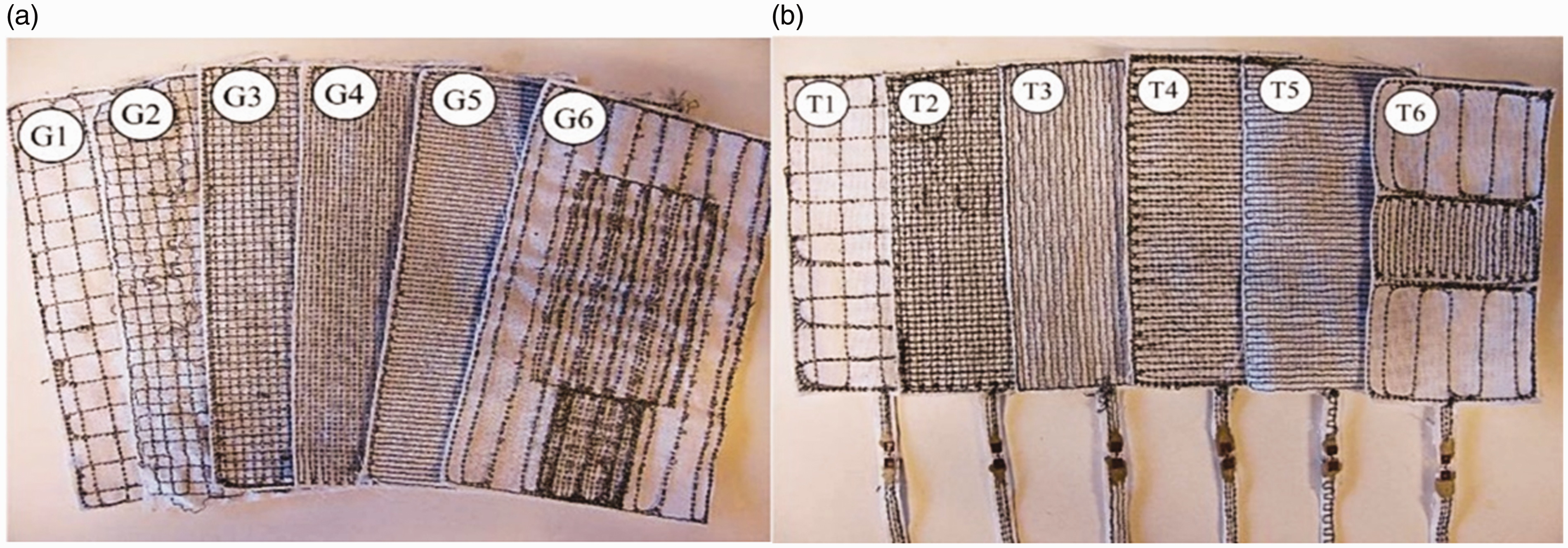

There are some bright and promising prospects in wireless body-centric sensing systems that warrant the redesigning of intelligent wearable systems through the extension of advanced fabric functionality. This work focuses on wearable patch antennas for RFID-enabled sensing systems. The initial modeling parameters for the embroidered antenna patch and ground plane structures were presented. A number of prototype antennas were designed, fabricated, and measured for verification purposes. The attained design guidelines were utilized to realize a fully wearable embroidered RFID patch antenna. The tag posed an extremely low back lobe level, which is required for good robust antenna performance and antenna-to-body isolation. Furthermore, a 4-meter read range was provided by the antenna.
Figure 10 shows an implementation of the design of on-body measurement of the antenna on a 0.126-mm thick Kapton HN polyimide film ( Dipole tag antenna optimized dimensions: l = 90, l2 = 30, l3 = 20, w = 3, w2 = 5, h = 13, h2 = 9, and d = 2.
26
Measurement of dipole tag on-body read range female and male in the +z-direction for the (a) upper arm, H-plane (yz-plane); (b) head, E-plane (xz-plane); and (c) chest, E-plane (xz-plane).
48


The differences in body locations are accommodated by maintaining the total size of the tag antenna by keeping the size adequately small. The two arms of an antenna are folded to realize the accommodation initiative. Outfitting the dipole antenna with a T-matching loop (parameters l2, h2, w2), which alters the capacitive tag antenna input reactance component into an inductive one, is put in place. 48
In Manzari et al.,
49
an investigation was executed on an antenna that possesses a quarter-wavelength patch that was linked to the RFID IC chip via the H-slot top. The shape factor was selected for the production of the important input impedance for microchip matching. Figure 12 shows a 3-mm thick substrate synthetic felt produced from carved adhesive copper conductors. As the experiments demonstrate, achievable RFID passive body-centric connections could be attained inside a typical indoor room with the prevalent available technology, with precautionary measures taken in overcoming dangerous incidents being executed. In order to avoid excessive absorption and shadowing processes, the human body tags placement should be selectively chosen.
49
Electro-textile wearable tag, made of adhesive copper and felt. The dimensions (in mm) were L = 59, W = 80, a = 15, b = 15, p = 14, d = 10, L
g
= 70, g = 3, h
s
= 3, and W
g
= 90.
49

The effects of the human body movement activity and posture in terms of link shadowing is dependent on the positioning of the reader-antenna and numerous dissemination phenomena.
50
Connections between proximate body parts (waist–torso, arm–forearm) are predominant in the form of creeping waves. Meanwhile, the communications between remote areas of the body, such as head–waist, arm–leg, etc., are affected by the diffraction and reflection of body parts. A folded rectangular plate around a dielectric slab of the thickness (h
I
) and height ( (a) Folded patch H-slot antenna. (b) Fabricated TAG-1 and 2 prototypes of the human body-worn antenna.
51
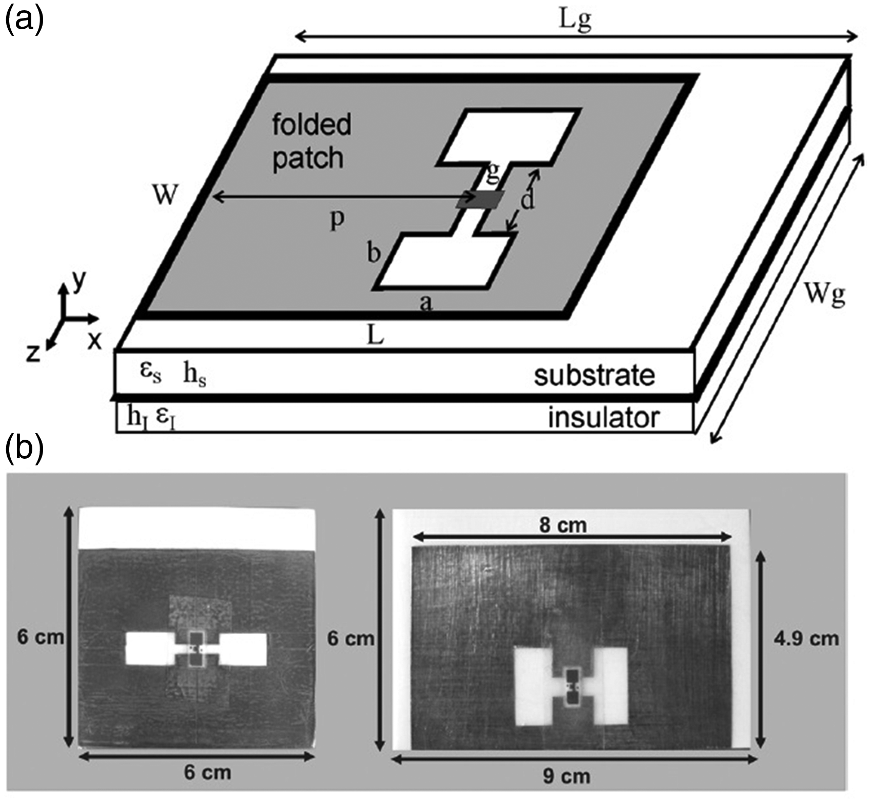
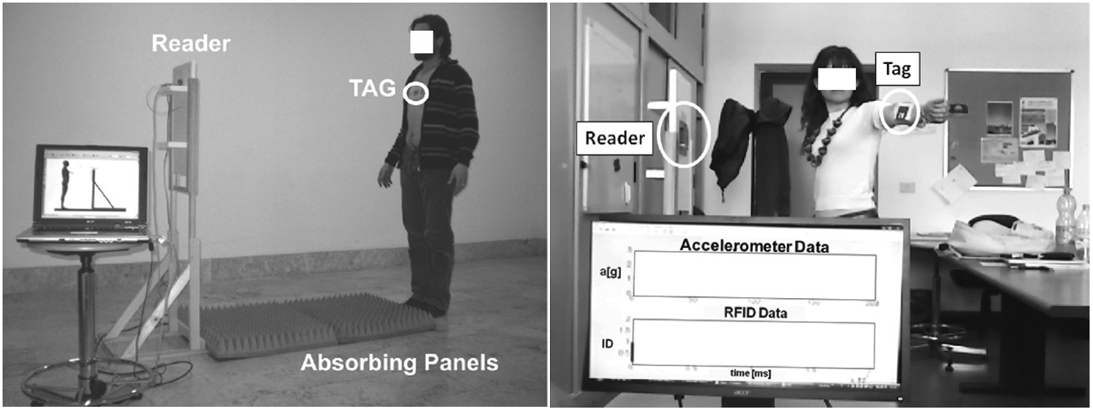
Advancements in this area of endeavor will require the actualization of flexible conformal prototypes on the foundation and principles of textile technology. The design achieved is of the size similar to a credit card, which is applicable to any part of the human body. The result indicated the possibility of using these technologies in body-worn tags for real-time monitoring of human activities. The antenna was operated over the volunteer's leg and the power transmission coefficient (at 869 MHz) of the order of (TAG-1) The short-range reader (measurement setup).
51
In Koski et al.,
52
an elaboration on the material choice for wearable passive UHF RFID antennas for signal strength-based RFID positioning can be seen (Figure 15). From our analysis, we concluded that wearable antennas that were fabricated using the embroidery technique demonstrate the same link loss and shadowing effects as experienced by antennas that were constructed from uniform conductive fabric. This highlights the feasibility of embroidered antennas in indoor localization applications. In the future, techniques using embroidery will provide ease in the sturdy incorporation of antennas with clothing, which in turn will build public confidence and industrial approval toward the technology.
52
Wearable embroidery antenna: (a) top view; (b) bottom view; (c) antenna attached on the arm of a volunteer.
52
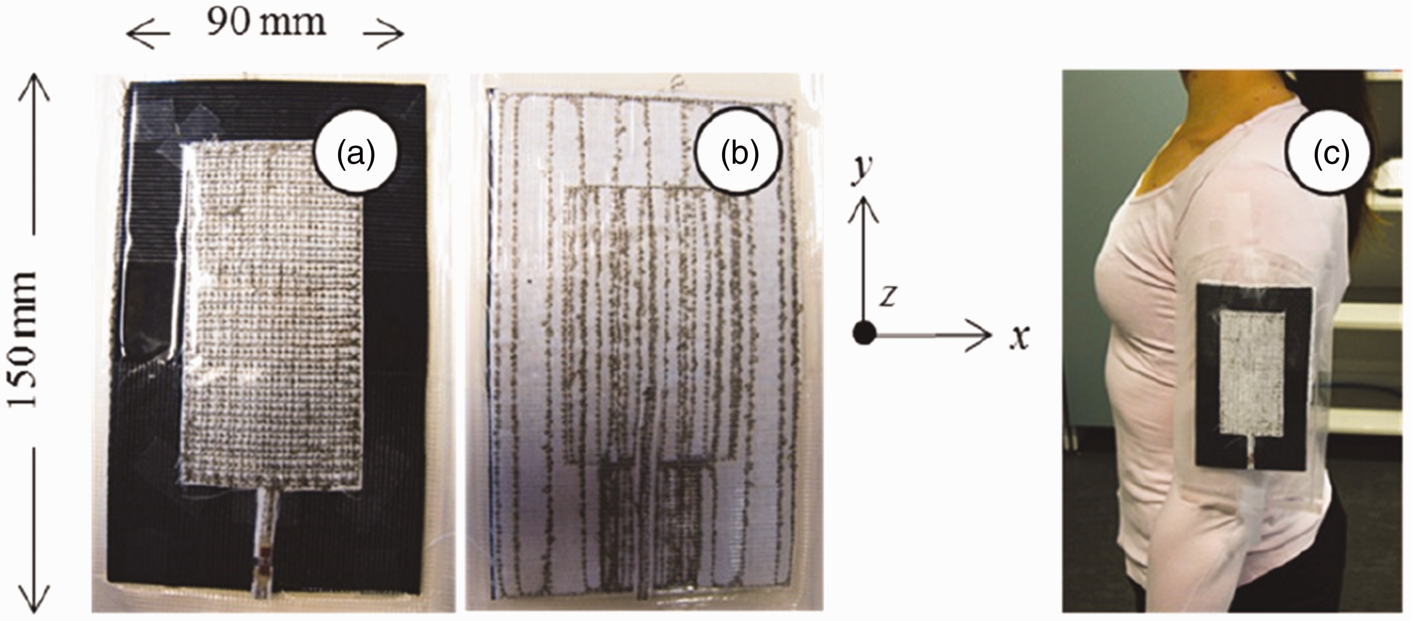
A lesser effect is experienced by the microstrip patch when placed close to the body or on it. Wherever the antenna is placed, the front–back ratio defines the power differences that are seen to emit in opposing directions. The ratio change is dependent on the type of antenna and its position located on the body. The full ground plane patch antenna affects a reduction in the back radiation antenna when positioned on the body. 53 It is evident that the optimal choice for wearable antennas is the microstrip patch antenna.
In Abbas et al.,
1
a novel fully textile UHF RFID tag antenna has been developed that can be easily integrated with clothes. This is an electrically small antenna with dimensions of 72 × 20 × 2.75 mm3. A flexible and totally wearable textile antenna is proposed by embroidering the conductive threads into garments. A purely polyester substrate has been utilized, which provides a tag that can be easily integrated with clothes (Figure 16).
Slotted tag antenna: (a) top view; (b) ground plane; (c) side view, where L = 74, W = 20, Wa = 15.5, slw = 4.25, sll = 25, tll = 12.25, tlw = 2, d = 0.49, Ca = 2, Cb = 1, h1 = 1, h2 = 4, and h3 = 2.5.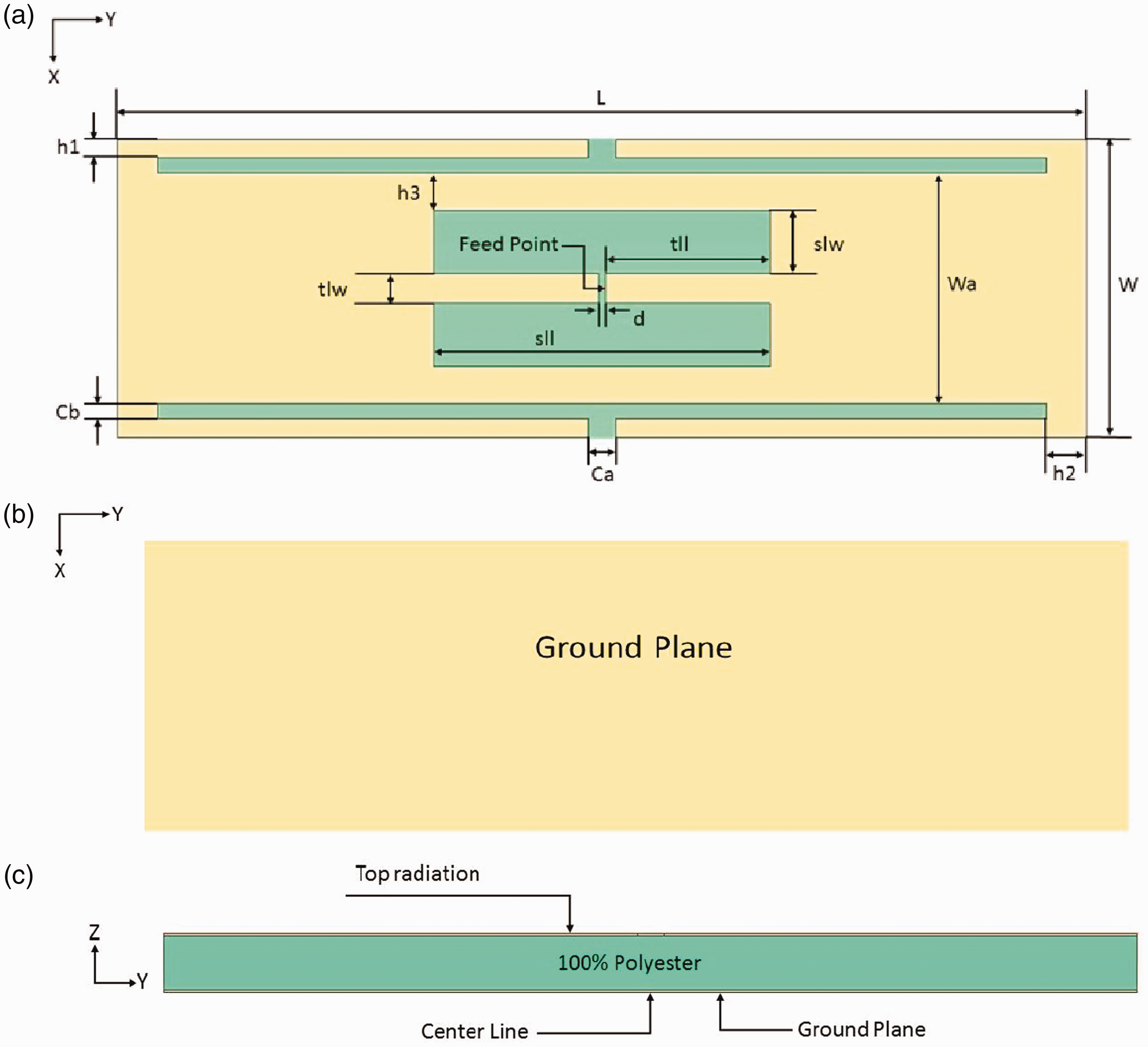
The interaction between the human body and the antenna
Wearable antennas are positioned in close proximity to the human body. This situation will affect a high dielectric constant and loss, which can have damaging and harmful effects on the effectiveness and impedance of an antenna input. The human body has an impact on the impedance features of transmission lines. It causes a mismatch, electrical length alterations, and a marked increase in loss. Thus, it has a potential impact on the operation of impedance.
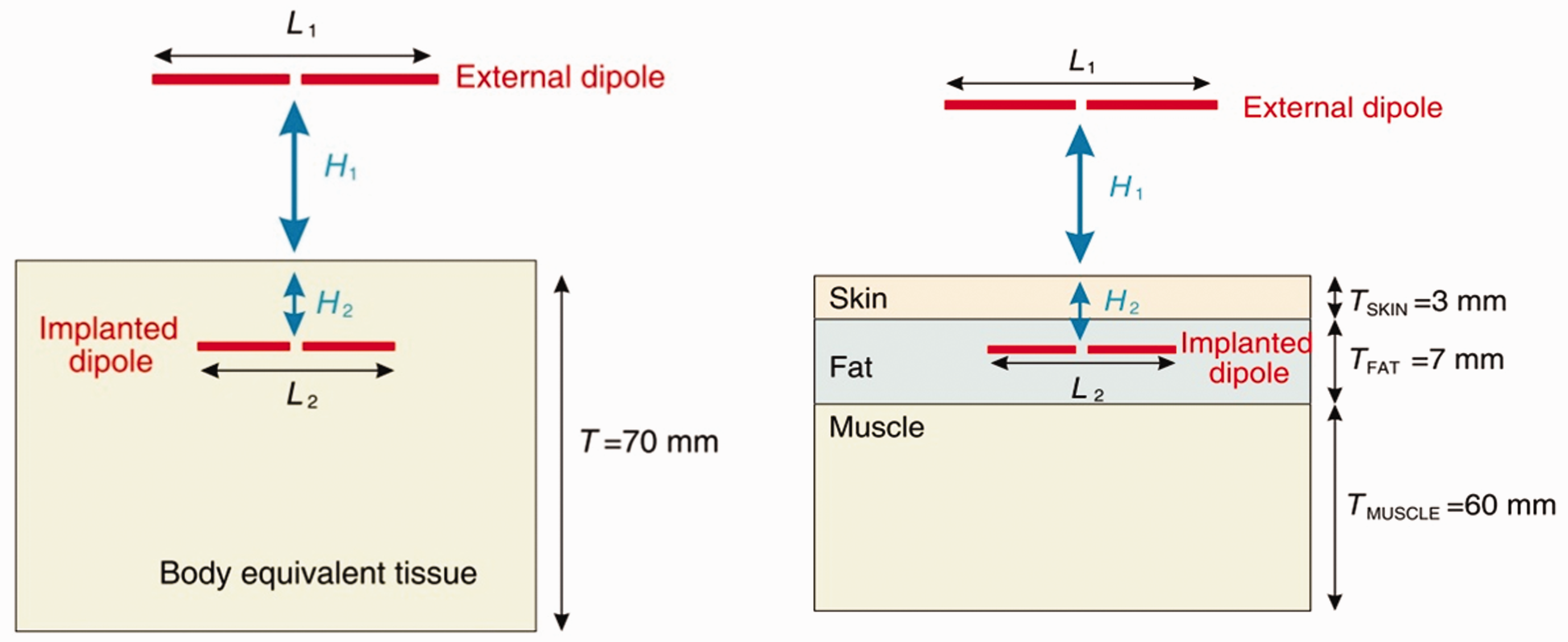
The propagation losses of a link between an implanted antenna in a human body and that of an external antenna at the industrial, scientific, and medical (ISM) bands of 433, 915, 2450, and 5800 MHz was assessed in a study.
54
The impact of the implanted antenna inside the human body can be seen in heightened propagation losses and dimension reduction. These results were caused by the characteristics possessed by the human body that demonstrate high conductivity and high permittivity. In predicting antenna behavior, the one-layer model (measurements and simulations) and the three-layer model (simulations) are adopted as body models
54
(Figure 17).
One layer of body equivalent tissue and the three-layer (skin–fat–muscle) simulation scenario.
54
There is a complete obstruction for the antenna radiation through the body and, thus, several tags are required for omnidirectional patterns.
Model showing possible statistical catalog of the human body 48

One of the potential statistical catalogs of human body models is represented in Table 3. The designer of wearable antennas would fix the model parameters according to the target group (subject). The choice of model dimensions was in accordance with the tag location application. What should be noted is that in the future, the extension of the catalog may include complete and omnipresent cover tag location possibilities. In addition, any desired division might be chosen for the target group. In view of the short time duration for the completion of one set of measurements for a given subject and tag location, the desired catalog might derive time efficiently. The inadequate energy possessed by the non-ionizing radiation (microwave, visible light, and sound waves) for ionizing molecules or atoms demonstrates a slight twist. It, however, possesses sufficient energy to mobilize atoms or induce them to vibrate. Therefore, the non-ionizing radiation has the capacity and sufficient energy for increasing the temperature of cells and mobilizing these cells.
The rise in temperature has a significant impact on human tissues, resulting in dielectric heating. This thermal effect is the consequential effect of microwave radiation occurrence brought about by the heating of dielectric material through the rotations of polar molecules induced by the EM field. The Specific Absorption Rate (SAR) is the parameter utilized to measure the human body tissue energy absorption rate.
The rate at which RF-EM energy is imparted to the unit mass of the biological human body is referred to as the SAR. It is a measure of the human body energy absorption rate when it is exposed to RF-EM field. According to the norms, the SAR is averaged either over a small sample volume (typically 1 or 10 g of tissue), or over the whole body. The value cited is then the maximum level measured in the body part studied over the stated volume or mass. The formula of SAR calculation is given as

The SAR should be compliant with the limits of the ‘International Commission on Non-Ionizing Radiation Protection (ICNIRP) and IEEE.’10,12
Figure 18 illustrates the three main models successful in characterizing the SAR in the human body.
56
In 2002, a numerical model of a human head (Figure 18(a)) was developed by Wang and Fujiwara,
57
which consists of 17 various tissues and a voxel size of 2 × 2 × 2 mm3. The model constitutes of more than 520,000 cubic voxels, each of which has a volume of 8 mm2, where each volume was assigned to a specific type of tissue.
58
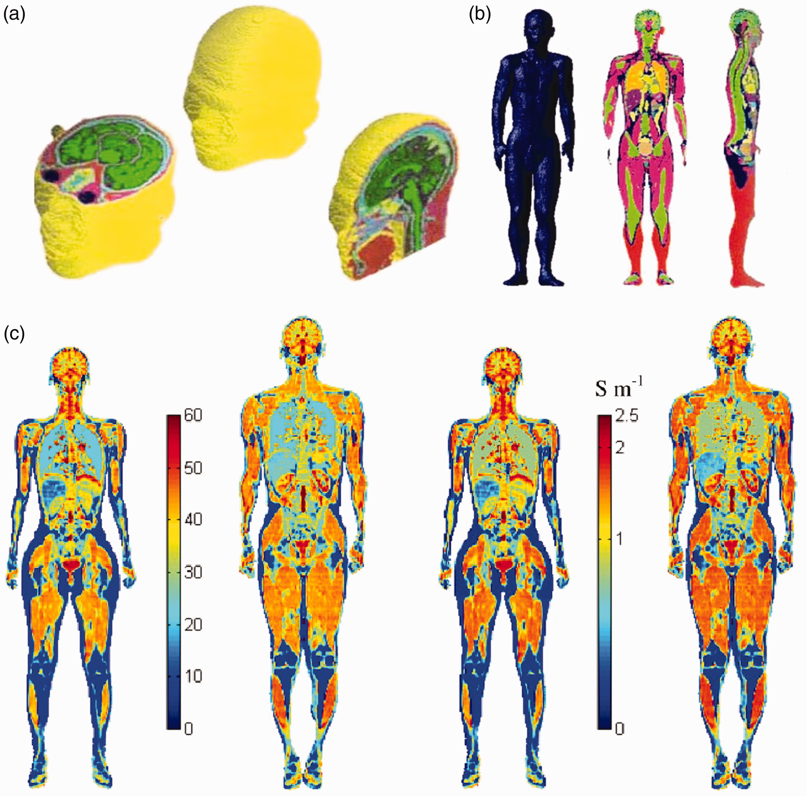
A numerical model based on magnetic resonance imaging (MRI) data of a whole-body adult male was developed in 2004, consisting of 51 tissue types and a voxel size of 2 × 2 × 2 mm3 (Figure 18(b)).56,59 It took three full years for the completion of this model, which has a resolution of 2 mm and a voxel volume of 8 mm2. The results of this experiment are illustrated in Figure 18(c), where it is shown that a dielectric anatomical model can be utilized to generalize the exposure to RF radiation from the far-field. 60 Motivating preliminary results have shown that the body-worn efficiency might not monotonically increase with increasing antenna–body separation.
For future research, different antennas as well as various distance frequency effects should be investigated. 3 Before the emergence of wearable antennas in consumer applications, other open-ended questions should be addressed, such as materials, durability, manufacturing problems, and the effect of the human body on printed transmission lines. Wearable devices will become very important in different areas, such as safety, health, management, environment monitoring, sports, biomedical, and tracking, as well as other impactful applications.
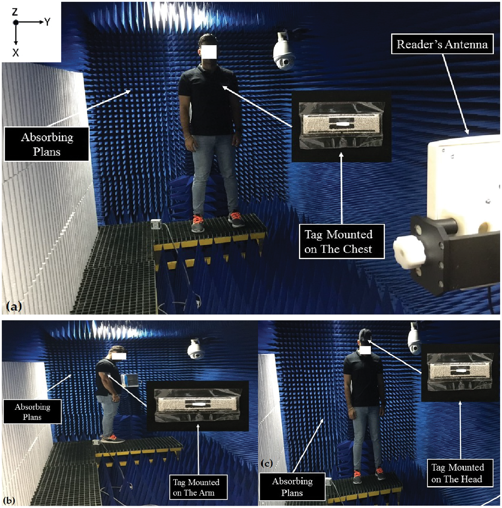
In order to further investigate this issue, tags were attached in Abbas et al.
1
at two locations on a T-shirt at the arm and chest, and on a cap for the head, shown in Figure 19. Basically, it is difficult to attach an electro-textile tag accurately at identical locations, especially if the tags are bent on the body surface, such as on the chest, where the uncertainty of the model would be more significant. However, the simulation and measurement confirmed the reliability of the proposed design with respect to the reading performance. In addition, the used antenna components are unique, since they are totally flexible and fully textile. Conclusively, literature surveys have indicated that there is huge potential to improve antenna designs in order to achieve better performance when applied in close proximity to the human body.
Reading distance of the antenna when located on (a) the chest, (b) arm, and (c) head, as measured in the +z direction.
1
Conclusion
In summary, this paper is a review of electro-textile wearable tags involved in the body-centric area particularly examining microstrip patch antennas, since they radiate perpendicularly to the planar structure, of which their ground plane shields the human body efficiently. The crucial features of conductive and non-conductive textile materials used in designing wearable antennas were reviewed. Therefore, the SAR by wireless devices was defined to characterize the absorption rate and hence study the effect of electro-textile design on the human body. For that reason, for the experiment the statistical cataloging of human body models by considering three locations in the human body—the head, the chest and the arm—is viewed as necessary. Wearable antennas are considered promising and show a significant future alongside the development of the rapidly emerging wireless communication technology, given appropriate and non-complex manufacturing techniques be deployed. The main approach of this review is to be the benchmark that could be used to choose the materials and techniques to design a textile wearable tag in the BAN. The embroidery textile slotted patch design antenna with specific materials proved in this study to have high performance.
Footnotes
Declaration of conflicting interests
The authors declared no potential conflicts of interest with respect to the research, authorship, and/or publication of this article.
Funding
The authors disclosed receipt of the following financial support for the research, authorship, and/or publication of this article: This work was supported by the Ministry of Education Malaysia for Fundamental Research Grant Scheme (project number FRGS/1/2014/TK06/UPM/02/5).
