
Abstract
It is very challenging to experimentally characterize and verify the airflow in the rotor spinning machine because the process takes place in an enclosure. In an attempt to portray the process, we present a methodology that combines a novel experimental approach and numerical techniques. We developed a model unit and used colored smoke to mimic the airflow behavior practically, measured the air pressure, and compared the results to the simulation data. Three state conditions, namely suction and rotation (the regular rotor spinning operation, (Case 1)), without rotation (Case 2), and without suction (Case 3), were adopted to investigate the formation mechanism of the airflow field in the rotor spinning unit based on two operating conditions. Results show that, in a regular state, the airstream accelerates rapidly in the transfer channel under the dominant action of air suction at the rotor outlet and crashes clockwise to the rotor wall with the joint action of two operating conditions. In the rotor, the airflow flows clockwise with the velocity distribution of a multi-ring gradient due to the dominant action of high-speed rotor rotation. Analytics from the air pressure indicate that while the air pressure in the rotor is mainly controlled by the action of the air suction mechanism, it is also affected by the superposition action of the rotation mechanism. This approach is groundbreaking for rotor spinning machine optimization and is anticipated to trigger more insights that will lead to fundamental research in the spinning industry and beyond.
Rotor spinning is the most widely used new spinning technology to commercially process fibers into yarns, with the advantages of low cost of production, high productivity, process automation, and flexibility to produce various novel yarns.1–4 Airflow plays a crucial role in the spinning process of rotor spinning, which is responsible for transporting fibers in the transfer channel, transferring fibers into the rotor interior, and assisting in collecting fibers in the rotor groove. However, airflow may also hamper fiber orientation and eventually result in the deterioration of yarn quality. 5 Therefore, airflow studies can provide a fundamental benchmark and useful insights toward the understanding and optimization of the rotor spinning process, for instance, the airflow field characteristics and the effects of geometric and spinning parameters on the airflow in the rotor spinning unit and, hence, on yarn properties. 6
Numerous studies have focused on the airflow field in the rotor spinning unit employing the computational fluid dynamics (CFD) technique. In 1996, Kong and Platfoot 7 developed a two-dimensional (2D) computational model and simulated the flow patterns in the transportation zone of the rotor spinning machine. Their results revealed that the airflow patterns could be affected once the geometric dimensions of the transfer channel or opening roller velocity varied, then altering the configuration of fibers. Yang et al. 8 conducted numerical simulation on three-dimensional (3D) flow in the transfer channel and rotating rotor, and the results showed that the vortex generated in the rotating rotor, the airflow speed decreased on the slip wall, and high-pressure regions developed on the slip wall and rotor groove. Further understanding of 3D airflow characteristics in the rotor spinning unit can be found in the research of Lin et al. 9 and Xiao et al. 10 They simulated 3D airflow in the rotor spinning unit and investigated the effects of significant geometric and spinning parameters on airflow patterns. Their studies and results provide fundamental guidance for the selection and optimization of both the rotor design and spinning parameters.
To understand the effect of the airflow on the fibers and yarns, some researchers have conducted experimental studies. Zeng and Yu, 11 Guo and Xu, 12 and Pei et al. 13 adopted high-speed photography to capture and analyze the fiber motion in the airflow field at different operating conditions of air-jet spinning. Seyedi et al. 14 utilized the tracer fiber technique to investigate and analyze the fiber migration in the airflow field of newly rotor-jet spun yarn with the rotor-jet spinning parameters varying. Seyed et al. 15 and Lin et al. 16 carried on the spinning test to compare the yarn quality and hence verified the effect of the optimized transfer channel airflow field on the yarn properties. Akankwasa et al. 17 also evaluated the blended yarn quality to support the simulated results of the airflow characteristics in conventional and dual-feed rotor spinning machines. There are many simulation works on the airflow in the rotor spinning machine and some experimental methods to figure out and verify the effect of the airflow on fibers and yarns. Nevertheless, no visual experimental findings on the airflow in the rotor spinning unit in the industrial setting have been reported.
The rotor spinning operation is mainly controlled by the air suction mechanism and rotation mechanism, that is, air suction at the rotor outlet and high-speed rotor rotation. It is based on these two operating conditions that an appropriate airflow field is generated in the rotor spinning unit, therefore achieving fiber transmission, transfer, and accumulation. There are a few publications that have investigated the effects of the two operating conditions on the airflow field in the rotor spinning unit. Xiao et al. 10 studied the influence of rotor speed on the airflow, and their results showed a significant change of the flow structure in the rotor as the rotor speed varied. The research of Lin et al.9,18 indicated that more vortices around the rotor groove could be produced with lower rotor speed, and much higher rotor speed can cause more yarn breakage. Their studies on rotor outlet pressure revealed that it was beneficial to yarn production to decrease the rotor outlet relative pressure. Still, the vortex intensity on the transfer channel inlet can increase, resulting in a decrease in fiber straightening and yarn properties. However, there are no previous studies that have performed experimental verifications focusing on these two operating conditions and given attention to their contribution to producing the airflow field, namely, the formation mechanism of the airflow field in the rotor spinning unit.
This work aims to experimentally and numerically investigate the dynamic and static characteristics of the airflow field (i.e., airflow behavior and air pressure) in the rotor spinning unit. The formation mechanism of the airflow field in the rotor spinning unit is also analyzed by comparing the experimental findings and simulation results in three cases with two operating conditions being varied. Our work provides a further understanding of the airflow field characterization from a practical perspective, and the technique used in this work can be extensively utilized in other flow problems.
Experimental details
Experimental setup
The general rotor spinning unit of the air suction open-end rotor spinning is shown in Figure 1. An air pump is connected with the aspirating hole and sucks air out of the spinning unit. The air in the rotor is also sucked from the rotor outlet and then two airstreams are fed into the rotor from the transfer channel and doffing tube, respectively. Simultaneously, the rotor rotates at high speed. Thus, the specific airflow field and twisting environment of rotor spinning are generated.
Schematic diagram of the rotor spinning unit.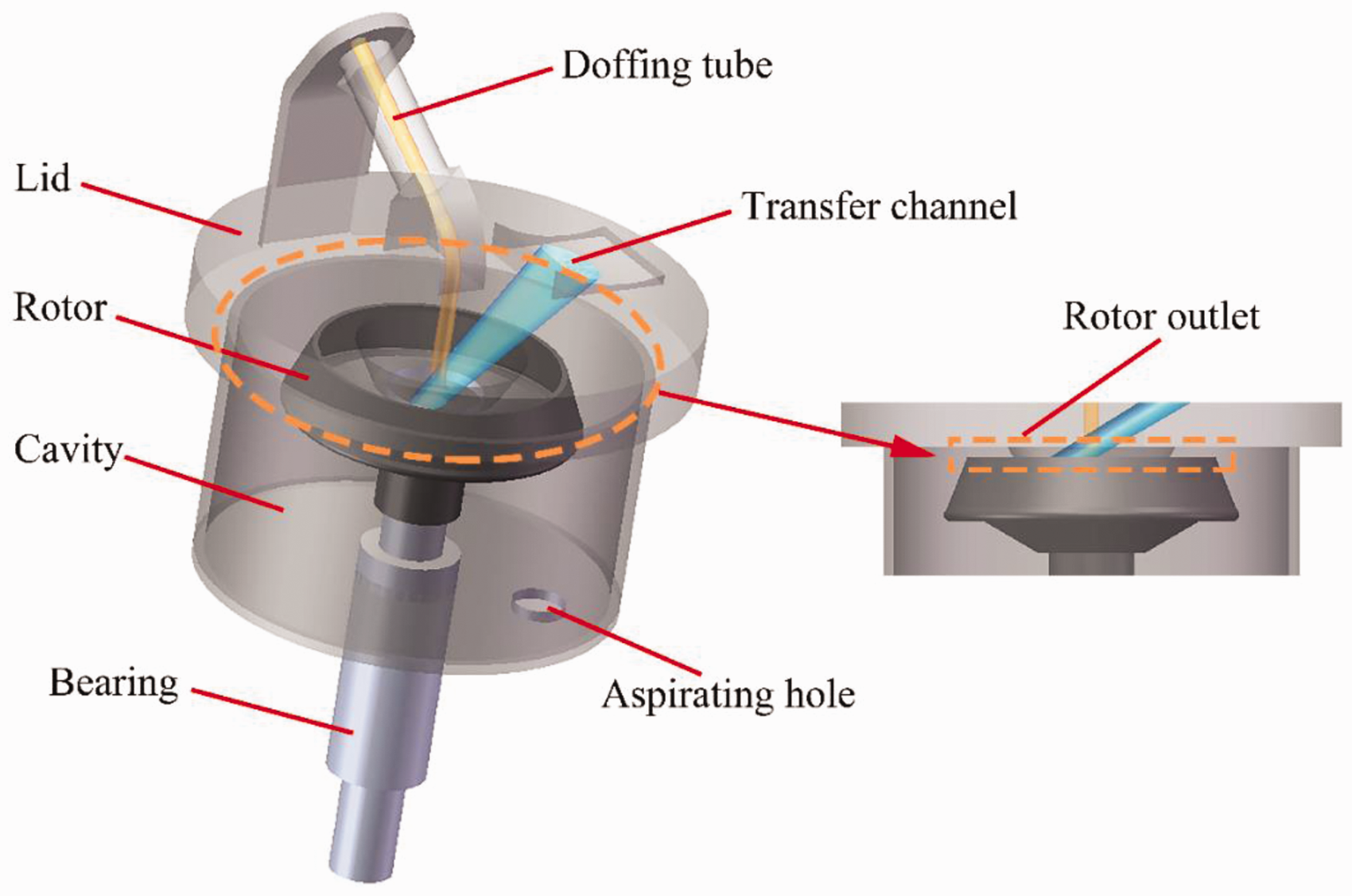
Since the rotor spinning unit is opaque and sealed in the actual spinning state, it is difficult to observe the airflow behavior and obtain the characteristics of the airflow field in the rotor spinning unit. To address this problem, a model rotor spinning device with a model rotor spinning unit (the model unit, for short) was set up based on the geometrical parameters of the actual rotor used in the open-end spinning (see Figure 2). The model unit consists of a rotor, a lid, and a cavity, all of which are made of plastics, transparent polycarbonate and resin, thus making it easy to view the rotor interior (see Figures 2(a) and (c)). The dimensions of the model unit are presented in Figure 2(d). Furthermore, in our device setting, an air pump was used to implement the air suction, thus providing the negative pressure required for spinning. The model rotor was driven by an electric motor through a flat belt to accomplish the high-speed rotor rotation.
(a) Schematic diagram of the experimental setup. (b) Model rotor spinning device. (c) Model unit. (d) Main dimensions of the model unit.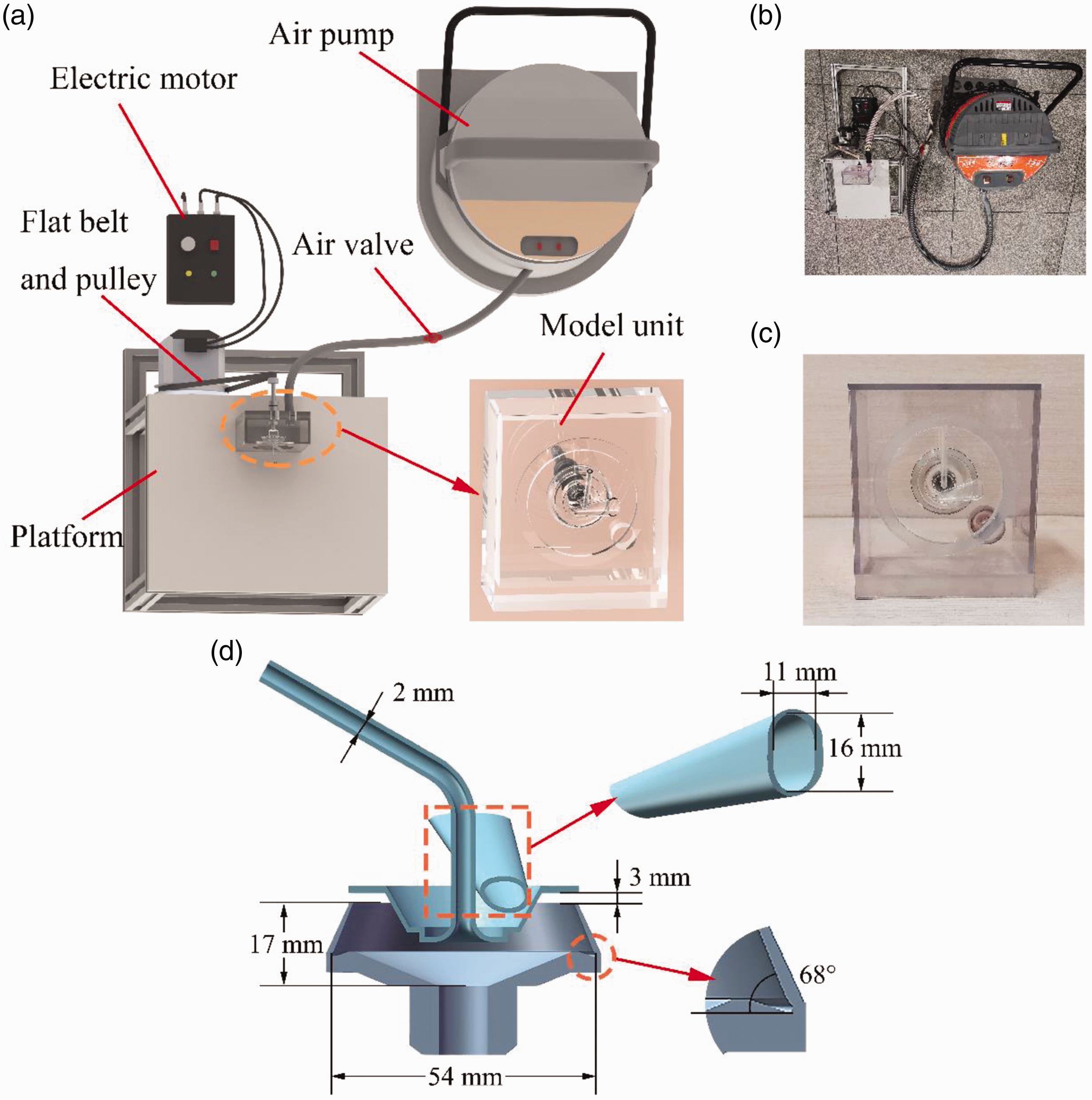
Experimental arrangement
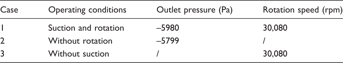
Details of the operating conditions in the three state conditions
Observing airflow behavior
In order to achieve a vivid observation of the airflow behavior in the model unit, we introduced a reddish-violet smoke into the inlet airflow. This colored smoke flows with the airstream in the model unit and thus adheres to the model unit. This phenomenon makes it possible to visualize the airflow due to the distinctive color of the airflow and the transparency of the device components. The transfer channel is the main airflow inlet of the rotor spinning unit and the only entrance for fibers during regular spinning. Hence, this study focused on the flow behavior of the airflow from the transfer channel to the rotor interior. The colored smoke was introduced in the airstream at the inlet of the transfer channel and the introduced amount in all three cases was 0.894 g. We then used a camera (FUJIFILM X-T3, 24 fps) to capture and record the colored airflow behavior in the model unit.
Measuring air pressure
The measurement of air pressure was also conducted based on the developed model unit. Four circular holes were punched on the model lid to insert the pressure gauge probe. While one of the punched holes was in use, the other three holes were blocked. The four holes correspond to four lines locating the points selected for further air pressure measurement and analysis. As shown in Figure 3, the four lines are parallel to the center axis of the rotor and equidistant from the center axis. Line 1 intersects the center axis of the transfer channel at point A, and Schematic diagram of the pressure measurement points and their located lines in the (a) x–z plane and (b) x–y plane.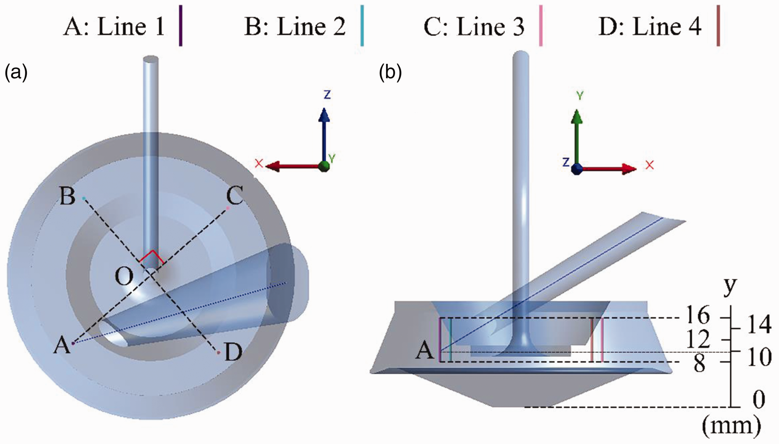
Experimental results
Observation results of airflow behavior
The process of the colored airflow flowing into the model unit in the three cases is illustrated in Figure 4, where t represents the time of the colored smoke being introduced into the airstream at the transfer channel inlet. The model units in all three cases were all clear at Sequence images of the colored airflow behavior inside the model unit in (a) Case 1 (suction and rotation), (b) Case 2 (without rotation), and (c) Case 3 (without suction).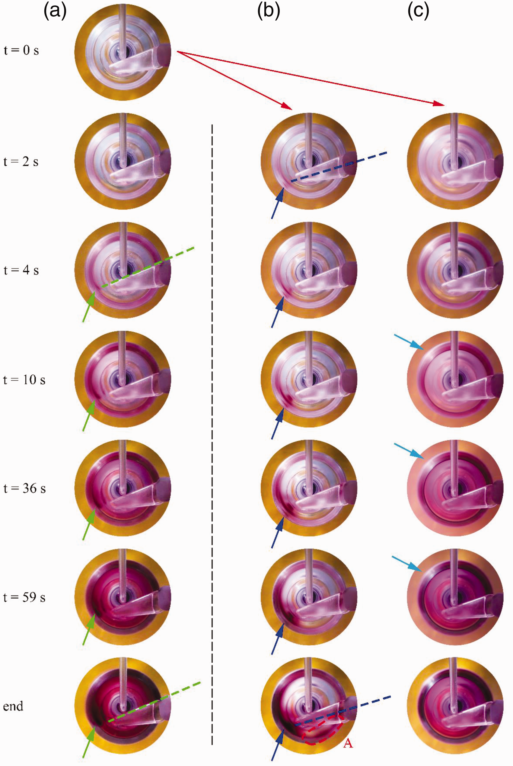
Figure 4(b) shows an entirely different airflow behavior from that exhibited by Case 1 in the same conditions. The colored marks both on the lid and rotor wall in Case 2 were mostly concentrated at the exit of the transfer channel and then dispersed along the upper and lower rotor wall and lid (see the arrows in Figure 4(b)). The colored spots on the left-hand side of the lid were distributed radially at the transfer channel outlet, and the colored marks were concentrated closer to the transfer channel outlet. This observation revealed that the airflow coming from the transfer channel crashed directly onto the rotor wall. This was followed by two airstreams that flow respectively along the upper and lower rotor wall. Simultaneously, there was also part of the air flowing out of the rotor outlet. Furthermore, some stained blots appeared in zone A on the lid at
Measurement results of air pressure
Figure 5 illustrates the measurement results of the air pressure in the three cases. It can be seen that the measurement values in Case 1 (–3500 to –7000 Pa) are close to those in Case 2 (–4000 to –9000 Pa), while the pressure values of the selected points in Case 3 are kept in the range from 0 to –500 Pa. This phenomenon reveals that the air suction mechanism mainly generates negative pressure in the rotor at the regular spinning state. From Figures 5(a) and (b), it can be seen that the pressure of the points on Line 1 fluctuates greatly, and shows a trend of descending first and then rising with the increase of y. We attribute this to Line 1 being opposite to the transfer channel outlet. Nevertheless, as demonstrated in Figures 5(a) and (b), the lowest pressure value on Line 1 appears at different selected points. In Case 2, due to the airflow coming from the transfer channel directly crashing to the rotor wall along the direction of the center axis of the transfer channel, the velocity of intersected point A is supposed to be the largest. Given that the gravity of air is negligible, according to Bernoulli’s principle,
19
the pressure at point A is consequently the smallest. Therefore, the negative pressure of the end closest to point A, that is, the point at Experimental pressure values in (a) Case 1 (suction and rotation), (b) Case 2 (without rotation), and (c) Case 3 (without suction).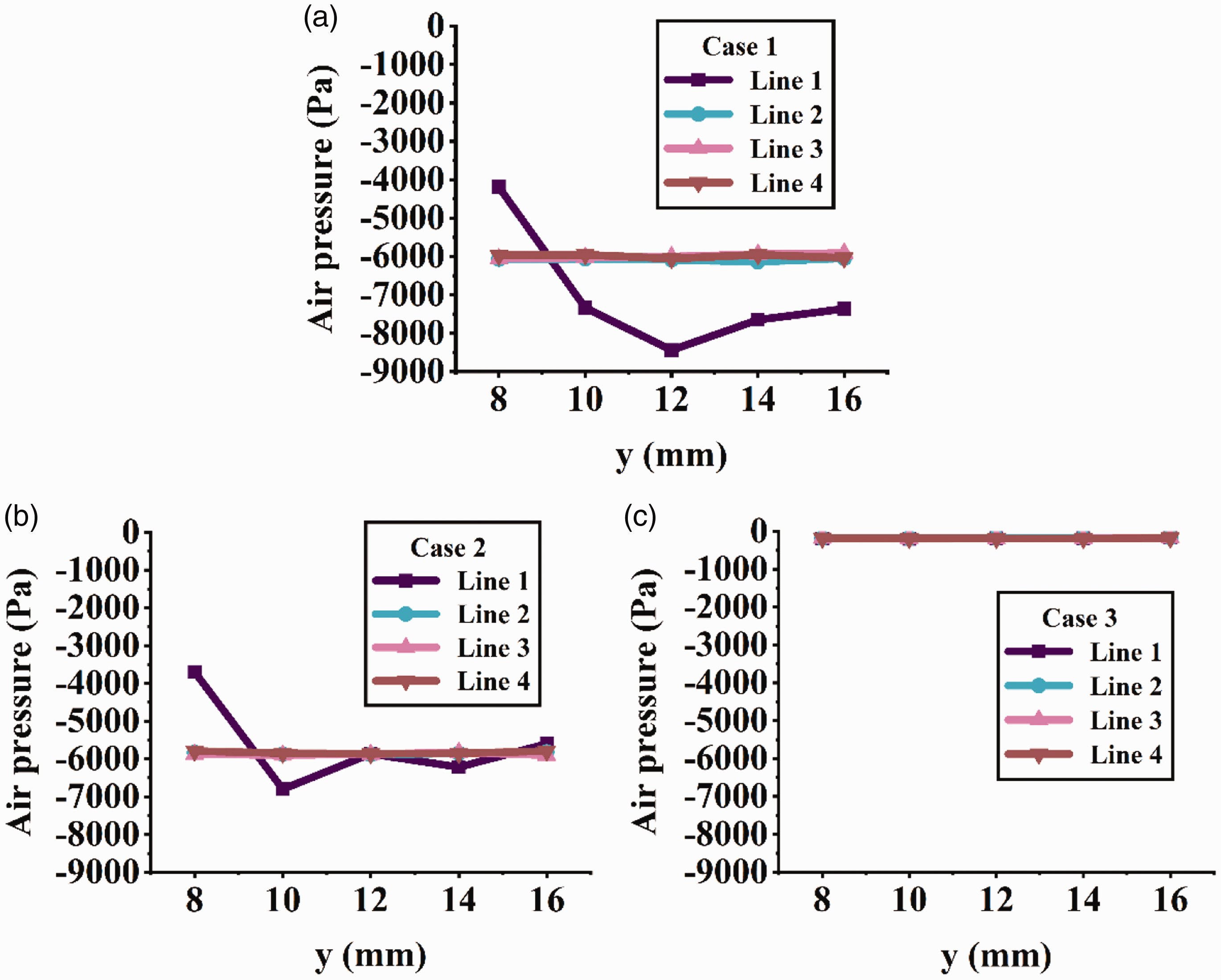
From the above analysis, it can be seen that not only the colored airflow behavior but also the air pressure in Case 1 (suction and rotation) can be roughly regarded as the superposition of those in Case 2 and Case 3 (i.e., without rotation and without suction). To further understand the dynamic and static characteristics of the airflow field in the rotor spinning unit, as well as investigate the formation mechanism of the airflow field based on two operating conditions, air suction at the rotor outlet and high-speed rotor rotation, numerical simulation of the three cases was also carried out.
Simulation scheme
The computational domain of the model unit is presented in Figure 6(a). There are two inlets, that is, the velocity-inlet and the pressure-inlet, and a wall boundary with the computational model. The velocity-inlet locates at the transfer channel inlet, and the inlet velocities measured by Pitot tube in Cases 1–3 are 28.87, 28.31, and 4.19 m/s, respectively. Since the doffing tube is open to the atmosphere, the corresponding inlet is set as the pressure-inlet with the pressure values equal to the atmospheric pressure (1.01 × 10⁵ Pa). The condition values of the outlet pressure and wall boundary in Cases 1–3 are the same as those in Table 1. Therein, the outlet pressure in Case 3 is –129 Pa.
(a) Meshed computational model and boundary conditions. Mesh independency test for three different grid schemes: velocity magnitude (b) along the x-axis at y = 10 mm and (c) along the y-axis in the direction of the center axis of the transfer channel.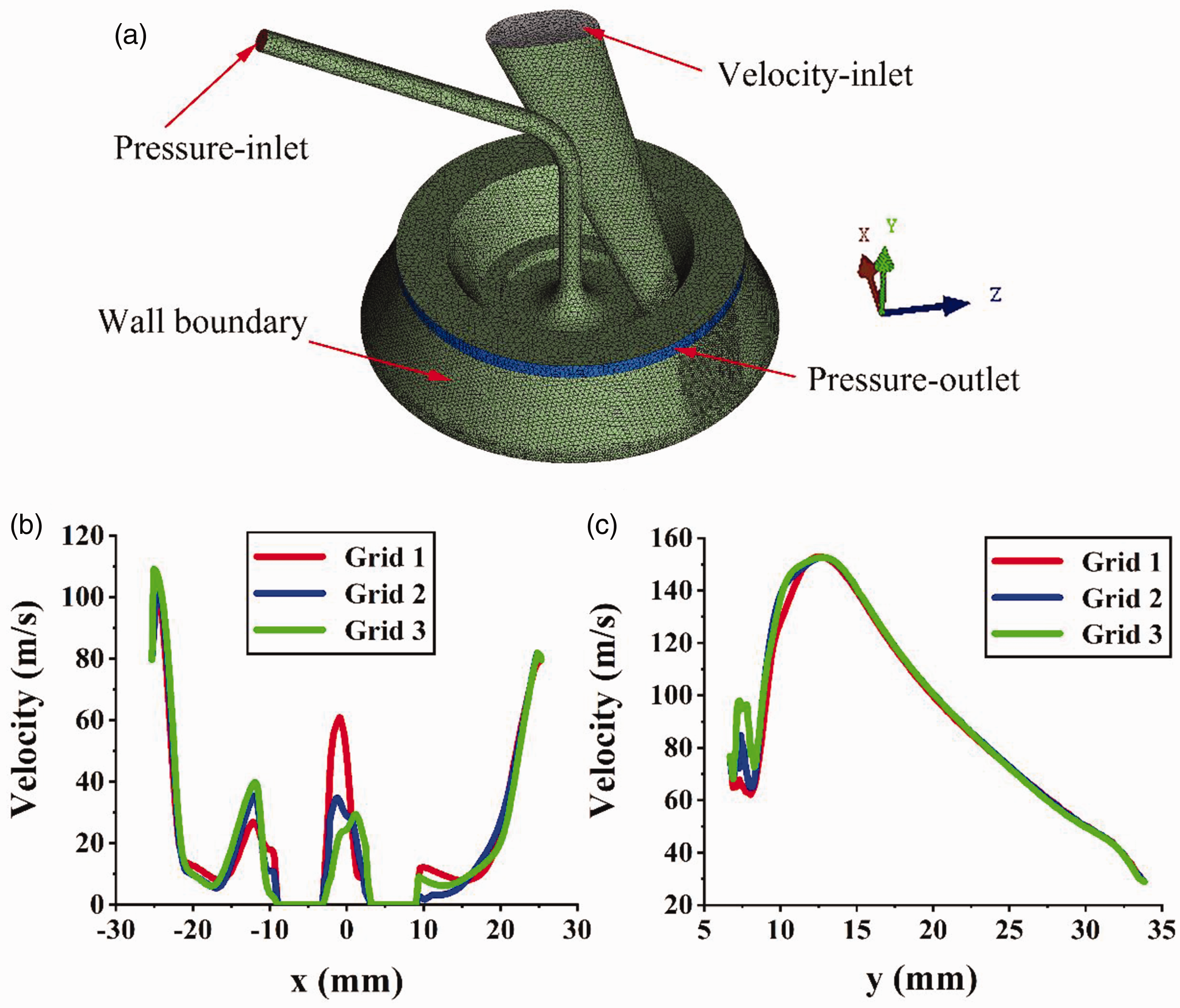
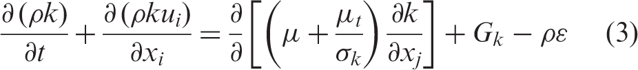
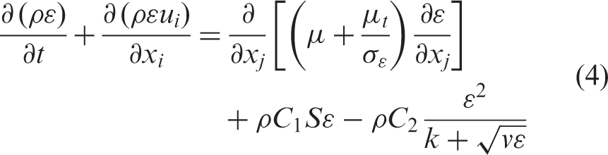
The airflow in the rotor spinning unit can be assumed as an isentropic, viscous, incompressible, and turbulent flow.6,7,9 There is minimal heat transfer in the rotor spinning process; hence, the governing equations considered here only consist of two equations. One is the mass conservation equation. Since the fluid density ρ is time-independent here, this equation can be expressed as

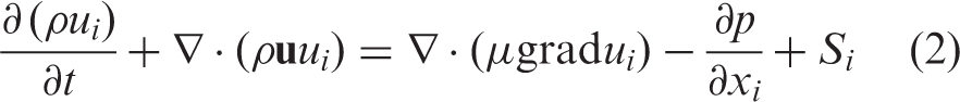
The wall functions are employed in the near-wall regions. The computational domain of the model was meshed into the unstructured tetrahedral cells with ICEM CFD 15.0, as illustrated in Figure 6(a). The governing equations were solved based on the finite volume method and the second-order upwind scheme using the commercial CFD package ANSYS Fluent 15.0. We achieved grid independence of the mesh by evaluating three grids with 842,637 (Grid 1), 1,193,867 (Grid 2), and 1,889,641 (Grid 3) elements (shown in Figures 6(b) and (c)). The results of the mesh independence test show that Grid 2 was more suitable for further simulation.
Results and discussion
Airflow behavior
According to the visualization results of the colored airflow mechanism in the model unit in the three cases, the airflow behavior in Case 1 showed an astronomical relationship with Cases 2 and 3. Therefore, the airflow behavior in Cases 2 and 3 was analyzed first, and the results were used as a basis for discussing the airflow behavior at a regular spinning state.
Without rotation
Figure 7 shows the simulation and the final experimental results in Case 2. As can be seen from Figure 7(a), the airstream accelerates once it enters the transfer channel inlet, which is on account of the negative pressure in the rotor generated by the air suction at the rotor outlet. The airstream velocity reaches the maximum v2, Numerical and experimental results in Case 2 (without rotation). The velocity streamlines of the airflow (a) in the rotor spinning unit, (b) in the rotor (
Without suction
In Figure 8(a), the airstream accelerates slightly in the transfer channel, indicating that the negative pressure generated by the high-speed rotation of the rotor is small. As shown in zone A in Figure 8(b), the airstream flows clockwise (the same direction as the rotor rotating) after exiting the transfer channel. Simultaneously, under the action of centrifugal force, the airflow keeps approaching the peripheral wall of the rotor and flowing toward the rotor outlet. This tendency results in the intense and uniform colored marks on the peripheral wall of the rotor (see the arrow in Figure 8(d)). Still, owing to the friction between the high-speed rotating rotor wall and the airflow, the velocity of airflow increases as it approaches the peripheral wall of the rotor. Thus, there is almost a multi-ring gradient distribution of the airflow velocity in the rotor, and the airflow closer to the peripheral wall of the rotor possesses a higher velocity, as shown by the blue arrow in Figure 8(b). The maximum airflow velocity v3, Numerical and experimental results in Case 3 (without suction). The velocity streamlines of the airflow (a) in the rotor spinning unit, (b) in the rotor (
Therein, n is the rotation speed of the rotor and R is the maximum inner diameter of the rotor. The velocity of the airflow near the center axis of the rotor is lower, which accounts for the visible reddish-violet smoke diffused inside the rotor in Figure 4(c). Furthermore, the airflow streamlines on the lid in Figure 8(c) are evenly distributed at the rotor outlet. This trend is consistent with the uniform slight marks on the lid in Figure 8(e), which indicates that the airflow flows out of the rotor and is also responsible for the visible reddish-violet smoke diffusing outside the rotor in Figure 4(c).
Suction and rotation
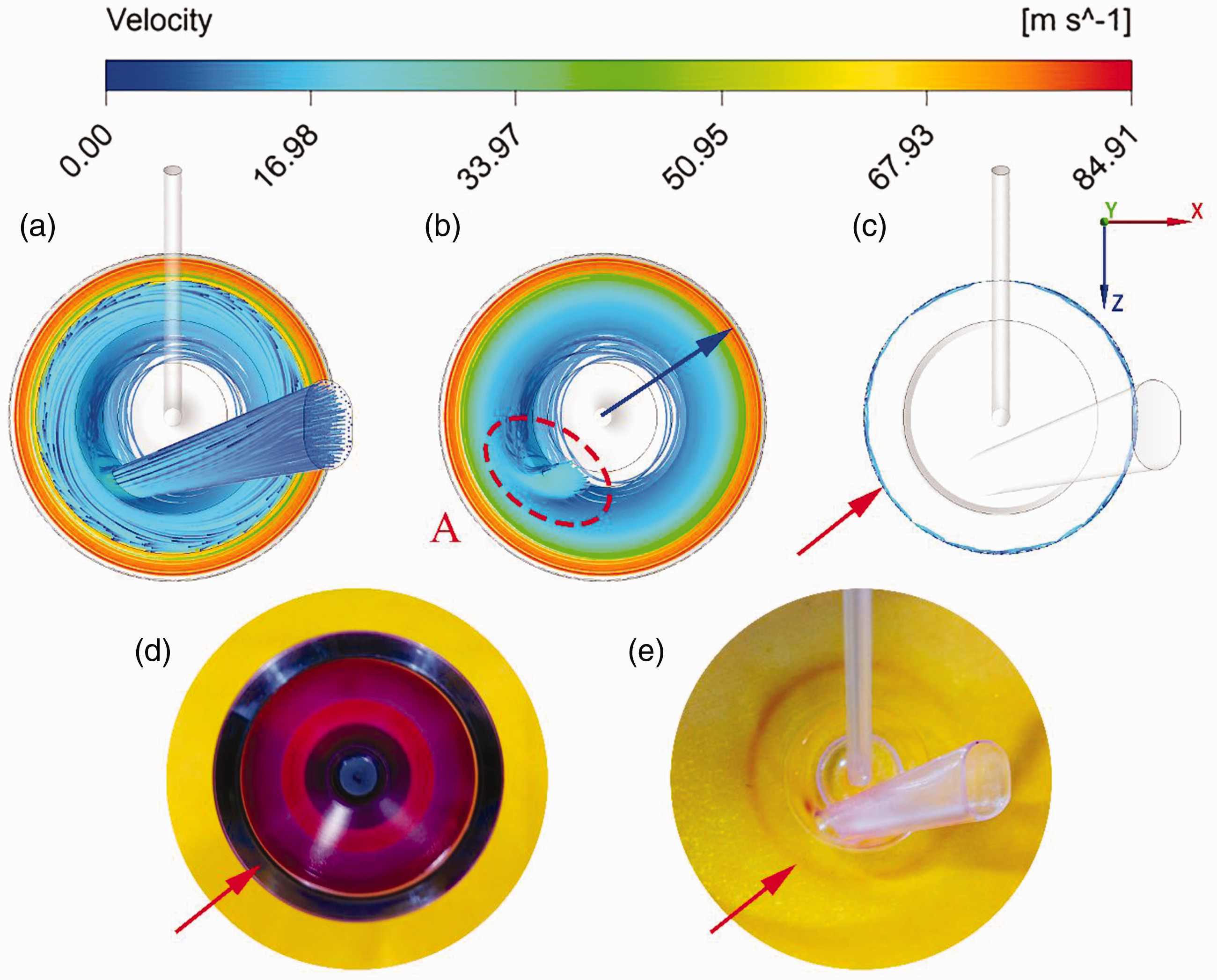
Figure 9 presents the simulation results and the final colored images of the model unit in Case 1, the operating conditions in which are used in the actual spinning process. In the transfer channel (see Figure 9(a)), the airflow behavior is similar to that in Case 2. The airstream accelerates rapidly as soon as it enters the transfer channel, hence achieving the fiber transmission, and the maximum airflow velocity v1, Numerical and experimental results in Case 1 (suction and rotation). The velocity streamlines of the airflow (a) in the rotor spinning unit, (b) in the rotor (
In the rotor, the airflow flows in the direction of the rotor rotating (clockwise), and the velocity streamlines inside the rotor are nearly distributed in a multi-ring gradient (see the blue arrow in Figure 9(b)), which is similar to that in Figure 8(b) of Case 2, but it does not look self-evident due to the maximum velocity occurring at the transfer channel outlet, not on the rotor wall. Therefore, it can be seen that the action of the rotation mechanism is dominant in the rotor, as well as in the spinning process. In addition, due to the centrifugal force, there is also a tendency for the airflow inside the rotor to flow toward the peripheral wall of the rotor, which contributes to the fibers suspended in rotor transferring to the rotor slide wall and the fibers accumulating in the rotor groove. Also, the concentrated colored marks on the rotor were uniformly aligned on the peripheral wall, and the rotor base had light-colored marks along the radius to the rotor center (see the arrows in Figure 9(d)). As the traces show in zones B and C in Figure 9, there is part of the airflow flowing out of the rotor. However, the traces only appear on the upper side of the transfer channel outlet instead of surrounding the transfer channel outlet like that in Figures 7(c) and (g) of Case 2. This trend indicates that the airstream exiting the transfer channel crashes clockwise to the rotor wall, and the high-speed rotation of the rotor eliminates the anticlockwise airstream.
Based on the discussion and comparison of the airflow behavior in the three cases varying in two operating conditions, it can be found that the two operating conditions jointly control the airflow behavior inside the rotor spinning unit in Case 1. The air suction mechanism ensures the primary airflow velocity necessary for achieving the fiber acceleration, transmission, and straightening. The rotation mechanism can eliminate the disruptive anticlockwise airstream formed by the geometrical constraints of the rotor under the action of air suction at the rotor outlet, thus assisting in the smooth transfer of fibers from the transfer channel to the rotor slide wall and the ordered arrangement of fibers. Meanwhile, the high-speed rotor rotation can also contribute to transferring the fibers suspended in the rotor to the rotor slide wall and accumulating fibers in the rotor groove. Besides, it can also be found that the numerical simulation results of the airflow behavior agree well with the corresponding experimental findings in all three cases.
Air pressure
Based on the numerical simulation of the airflow field in the rotor spinning unit described above, the simulated pressure can also be obtained. In order to further validated the simulation results, the simulated pressure values were compared with the measurement data in the three cases. As illustrated in Figures 10(a) and (b), the comparison results of the simulated pressures with the experimental data on the four lines in Cases 1 and 2 are similar. There is a deviation between the two outcomes on Line 1 in the two cases. Still, the overall trend of the two outcomes on Line 1 is the same, both descending first and then rising with the increase of y. There are two reasons for the deviation: in the first place, Line 1 is opposite to the transfer channel outlet, where the airflow changes the most drastically and complicatedly; secondly, the distance between the adjacent measurement points is very short, which may result in measurement errors. Regarding the other lines in Cases 1 and 2, the simulated negative pressure of each point is slightly lower than the measured result due to measurement errors. In Case 3 (see Figure 10(c)), the deviation between the simulated and experimental pressure values on Line 1 is also larger than that on the other three lines due to the specific position of Line 1. However, since the airflow field and negative pressure in the rotor spinning unit in Case 3 are generated by the high-speed rotor rotation and the negative pressure is small, the simulated and experimental results on the four lines are generally consistent. On the whole, the simulation values in Cases 1–3 are justified to conform with experimental data quantitatively.
Comparison of the simulated pressures with the experimental results in (a) Case 1 (suction and rotation), (b) Case 2 (without rotation), and (c) Case 3 (without suction).
Conclusions
In this work, we developed a novel experimental technique to make the airflow behavior in the rotor spinning unit visible. The results from experiments strikingly agree with the numerical simulation data and the related literature. In addition, we measured the air pressure inside the rotor and analyzed the measurement values, as well as the simulated results, quantitatively.
Two operating conditions, air suction at the rotor outlet and high-speed rotor rotation, are experimentally and numerically verified to jointly control the airflow behavior in the rotor spinning unit at the regular spinning state. In the transfer channel, the action of the air suction mechanism is dominant. The airstream accelerates rapidly from the inlet to the outlet of the transfer channel. After exiting the transfer channel, the airstream crashes clockwise to the rotor wall with the joint action of the two operating conditions. In the rotor, the act of high-speed rotor rotation is dominant. The airflow flows in the direction of the rotor rotating with the airflow velocity distributed in a multi-ring gradient from the peripheral wall of the rotor to the rotor interior. Besides, the air pressures inside the rotor, with fluctuation of descending first and then rising near the exit of the transfer channel and the relatively stable values away from the exit of the transfer channel with the increase of y, are mainly controlled by the action of air suction at the rotor outlet but are also affected by the superposition action of high-speed rotor rotation.
The technique employed in this study can accurately predict and analyze the rotor spinning process in more detail. Previously, it has been a classical challenge to experimentally verify the airflow and understand the effect of different parameters. We intend to utilize the visualization results in our study to investigate further other parameters and analyze other spinning techniques, such as dual-feed rotor spinning. This methodology can be adapted for other systems where airflow is a central phenomenon driving the system.
Footnotes
Author's note
Jun Wang is also affiliated to Key Laboratory of Textile Science & Technology of Ministry of Education, College of Textiles, Donghua University, China.
Declaration of conflicting interests
The authors declared no potential conflicts of interest with respect to the research, authorship, and/or publication of this article.
Funding
The authors disclosed receipt of the following financial support for the research, authorship, and/or publication of this article: This work was supported by the Fundamental Research Funds for the Central Universities and Graduate Student Innovation Fund of Donghua University (CUSF-DH-D-2019058) and the National Natural Science Foundation of China (Grant No. 11802161).