
Abstract
The chemical clogging of geotextiles filters is a common issue, which threatens the safety of engineering projects. To reduce the chemical clogging of nonwoven geotextiles and enhance their drainage capability, a polyurethane foam was innovatively placed under the nonwoven geotextiles in this paper. A series of column tests were conducted to study the mechanism of the polyurethane foam to reduce the chemical clogging of the nonwoven geotextile filters in tailings caused by ferrous iron. In addition, the influence of the concentration of Fe2+, hydraulic gradient and thickness of the tailings specimen on the chemical clogging of the polyurethane foam and nonwoven geotextiles was examined. Less chemical clogging of geotextiles caused by polyurethane foam was observed and the related mechanism was firstly explained. The polyurethane foam under the geotextile reduced the contact between the geotextile and air. As a result, the chemical clogging of the geotextile was alleviated, which increased the drainage capability of the geotextiles. A high water saturation of the polyurethane foam would help to a reduce the extent of the chemical clogging of the geotextile. The chemical clogging characteristics of geotextiles and polyurethane foam under different concentrations of Fe2+ and hydraulic gradients were observed.
Geotextiles have been widely applied in geotechnical engineering projects for filtration and drainage over recent decades, 1 and they have gradually begun to replace graded granular filters owing to their advantages, such as convenience of use and installation, environmental protection, reliable quality and low cost,2,3 as well as the increasing knowledge of and confidence in the behavior and performance of geotextile filters resulting from the amount of research. The main concern for the application of the geotextiles is the clogging problem. 4 The clogging of the geotextiles consists of physical clogging,5,6 chemical clogging 7 and biological clogging, 8 and the chemical clogging is more complex than the physical clogging. 9
Researchers have done a great deal of work on the chemical clogging of geotextiles.10–12 McIsaac and Rowe 13 simulated a typical leachate collection system in a landfill using a mesocosm setup, which showed that the nonwoven geotextile had higher resistivity to chemical clogging than the woven geotextile. Ferrous iron laden soils leading to ochre has resulted in excessive clogging of geotextiles filters, and the main threat to the good performance of filters is clogging by ochre, according to Koerner and Koerner. 14 Correia et al. 15 analyzed the effect of submersion in the formation of ochre biofilm in geotextile filters used in drainage systems. Several column experiments were designed to determine how ferrous ion causes chemical clogging of the Lixi tailings dam in China.16,17 The chemical clogging of geotextile filters caused by Fe2+ is a common issue, which threatens the safety of engineering projects.
Regarding the clogging of filter materials, many scholars have proposed countermeasures, such as the physical cleaning method18,19 and the chemical cleaning method.20,21 High-pressure jetting is regarded as a routine method to impede well clogging by fine sediments and biofilms. 22 Liu 23 discussed the prevention of chemical clogging on subsurface drain pipes, and put forward that SO2 could be added into the drain pipes to form HSO3 to dissolve and soften the iron compound. Nivala and Rousseau 24 applied hydrogen peroxide to the porous medium in an attempt to unblock the clogged constructed wetlands. Nevertheless, these recovery methods cannot clear all the clogging materials inside the filters effectively, which leads to a steady decline of the drainage capacity. In addition, the cleaning reagents may pollute the environment during use. Based on many studies,17,25 it is found that oxygen was required in chemical clogging, caused by Fe2+. In addition, the saturated polyurethane foam has the function of isolating air but allowing water 26 ; therefore, a layer of polyurethane foam was placed under the nonwoven geotextiles to alleviate the chemical clogging of the geotextile caused by Fe2+ and enhance its drainage capability in this paper.
In this paper, a series of column tests were conducted to study the influence of the polyurethane foam on chemical clogging of nonwoven geotextiles. In addition, the influence of the concentration of Fe2+, the hydraulic gradient and the size of the tailings specimen on the chemical clogging of the polyurethane foam and nonwoven geotextile was examined. The mechanism of the polyurethane foam to reduce chemical clogging was discussed.
Materials and methods
Geotextiles and polyurethane foam
The nonwoven, needle-punched geotextile was tested. Its mass per unit area was 200 g/m2 and thickness was 2.31 mm under zero normal stress. The apparent opening size was 0.099 mm (dry sieving test, O95) and its normal permeability was 1.58 E-3 m/s. The type of fiber was polyester fiber, and the manufacturer is Hebei Hongda Geotechnical Materials Co., Ltd, China.
Polyurethane foams were fabricated via the controlled entrapment of an expanding gas during the polymerization as the urethane links between the poly-functional alcohols and polyisocyanates were formed. 27 As polyurethane foams have the advantages of a low-density, high specific strength, high permeability and good elasticity, 26 they are ideal materials for the filter. In this paper, open-cell polyurethane foam was selected. There are a large number of cells in open-cell polyurethane foam, of which a portion were sealed by the film.
The thickness of the open-cell polyurethane foam was 15 mm with an apparent density of 32 kg/m3. The equivalent pore size of the open-cell polyurethane foam was 0.24 mm, as determined by the dry sieve method. 28 The permeability coefficient of the polyurethane foam was 3.18 cm/s, as measured using a vertical permeameter, which is similar to the permeability measurements of the geotextiles according to Darcy’s law. 29
Tailings sand
Tailings were collected from the drying bays of the Makeng tailings dam (iron tailings). The specific gravity of the tailings was 3.15 and their grain size distribution is as shown in Figure 1. According to Kenney and Lau’s
30
internal stability criteria, tailings were classified as internally stable. Their fine content (<0.074 mm) accounted for 70% of the total quality; d85 = 0.0989 mm, d50 = 0.0547 mm, d15 = 0.0157 mm and the non-uniform coefficient Cu = d60/d10 = 7.36.
Curve of the grain size distribution of the tailings.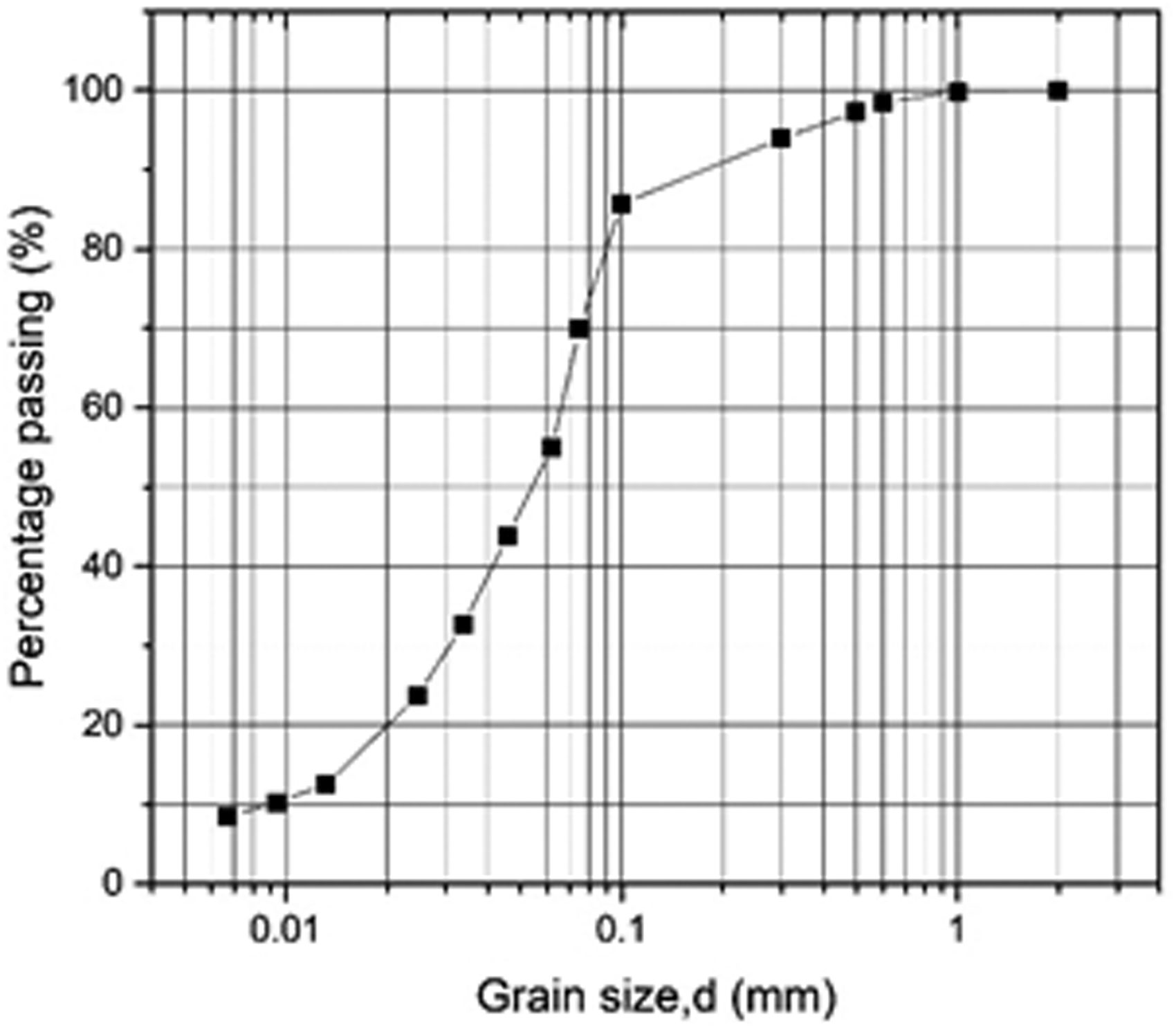
Apparatus
The tests were performed using a column permeameter capable of simulating the in situ condition of the geotextile filter in the tailings ponds. Figure 2 presents a schematic view of the apparatus. It could accommodate soil specimens up to 69 mm in diameter. The geotextile specimen rested on a perforated rigid plate, which allowed for the passage of piped soil particles to a lower chamber. The geotextile and perforated rigid plate were supported with a perforated cylinder. There were many holes in the supporting cylinder for air and water to pass through.
Schematic diagram of the experimental apparatus (dimensions in mm).
Several ports were distributed on the sides of the apparatus, and they had different functions. The solution was stored in a sealed bag to be isolated with air, and it was translated into the permeameter through a peristatic pump with port 1#. The peristaltic pump had a flow rate range of 3.8–19 ml/min. Port 2# was connected to the overflow port to keep the water head of the permeameter constant, and the overflow port was placed on a lifting platform that can adjust its height. A layer of oil was placed on the surface of the solution to isolate air. This apparatus adopted a downward seepage method. Therefore, the lower surface of the geotextile had an opportunity to come into contact with air to reproduce in situ conditions of drainage pipes wrapped with geotextiles. The solution flowed through the tailings and geotextiles into the lower part of the permeameter, then flowed out from the water outlet.
Experimental design
Experimental design

Test-1 to Test-4 were designed to study the influence of concentration of Fe2+ on the chemical clogging characteristics of the polyurethane foam and nonwoven geotextiles. In addition, Test-5 and Test-6 were designed to study the influence of the hydraulic gradient. Two concentrations of Fe2+ (100 and 1000 mg/L), three hydraulic gradients (2, 2.5, 10) and two heights of the tailings specimen (10 and 100 mm) were selected in these tests. Test-7 and Test-8 were designed to study the influence of the size of the tailings specimen. Considering the long time every test took, all tests were conducted once. Test-7 and Test-8 were conducted for about three months to study the long-term clogging process.
To reproduce in situ conditions, the nonwoven geotextiles and polyurethane foam in Test-1 and Test-2 were installed in an air dry state; however, the nonwoven geotextiles and polyurethane foams in the remaining tests were saturated. These saturated nonwoven geotextiles had been subjected to a12-hour saturation in water containing sodium alkylbenzene sulfonate with a volume fraction of 0.1%.
Experimental process
The experimental preparation is shown in Figure 3. A perforated supporting cylinder and a perforated plate were first placed on the lower part of the permeameter. The polyurethane foam (diameter of 69 mm) and the geotextiles (diameter of 85 mm) then were placed on the perforated plate. After the installation of geotextiles, the upper and lower parts of the permeameter were connected by bolts. Then the tailings were filled with a dry density of 2.10 g/cm
3
. The total filling height of the tailings was 100 mm for Test-7 and Test-8, and the tailings were filled by four layers, each 25 mm thick. For the rest of the tests, the total filling height of the tailings was 10 mm. The polyurethane foam was compressed by 2 mm in all tests.
Experimental preparation: (a) install perforated plate; (b) install polyurethane foam; (c) install geotextile; (d) fill tailings.
After filling the tailings, port 1# was connected to the peristaltic pump and port 3# was connected to a piezometric tube to record the water head of the system. Port 2# was connected to the overflow port, and the height of the overflow port was adjusted to the designed value by the lifting platform. The ferrous iron ion solution of the given concentration was prepared with FeSO4·7H2O and deionized water, and the solution was stored in a sealed bag.
The peristaltic pump was opened to input ferrous iron solution to the permeameter, and the flow rate of the peristaltic pump was constantly adjusted over time to guarantee the overflow of the permeameter. The experiment started, and the water head of the piezometric tube, the total iron concentration of the drainage water and the flow rate of the system were periodically recorded. The measurement interval was initially small and then increased. The total iron concentration of drainage water was measured with a Ferrover Kit. Once the flow rate of the system was stable, the water outlet was closed and the experiment was stopped. The duration of the tests was about 30 days, except for Test-7 and Test-8. During the experiment, the ferrous iron solution was prepared once a day.
After the experiment, pictures of the geotextiles and tailings were observed to analyze the clogging characteristic. In addition, the geotextiles were taken out for drying and weighing.
Results
Influence of concentration of Fe2+
This section describes the results obtained in Test-1 to Test-4. Under different concentrations of Fe2+, the chemical clogging characteristics of the geotextiles and polyurethane foams were assessed.
Morphology of chemical clogging
Pictures of the geotextiles after the experiment were observed to analyze the morphology of chemical clogging. When the concentrations of Fe2+ were 0 and 1000 mg/L, the pictures of geotextiles after the experiment are as given in Figure 4. To reproduce the site conditions, the nonwoven geotextiles in Test-1 and Test-2 were installed in the air dry state. For the geotextile in Test-1, the reddish-brown clogging substances were attached to several discrete regions and the margin of the face of the geotextile that came into contact with the perforated plate, and nearly no clogging film formed on this face. Most parts of this face had no chemical materials, as several preferential flow passageways formed when water flowed through the geotextile. When there was a polyurethane foam under the geotextile in Test-2, the color of the surface of the geotextile that came into contact with the foam became reddish brown, indicating there were a great number of clogging substances attached to the fibers of the geotextiles. However, the pore structure of the geotextile was not significantly changed by the clogging substances; hence, the clogging did not markedly decrease the drainage capability of the geotextile. The foam dispersed the water that passed through the geotextile and, as a result, the clogging substances were evenly distributed on the geotextile.
Pictures of nonwoven geotextiles after experiment in Test-1 to Test-4: (a) Test-1; (b) Test-2; (c) Test-3; (d) Test-4 (the inset figures were magnified by four times).
When the concentration of Fe2+ increased to 1000 mg/L in Test-3, it is clear that there was a layer of clogging film on the regions of the geotextile that came into contact with the holes of the perforated plate, and these films significantly reduced the drainage of the system. However, the remaining region of the geotextile only had a slight chemical clogging due to having no contact with air, and no film appeared. The farther away from these holes, the fewer clogging substances. Several films on the geotextile were destroyed in the process of taking it out. For the geotextile in Test-4, there were no films on it. However, its extent of chemical clogging was greater than that in Test-2, and there were more clogging substances on the fibers of the geotextile, as observed in Figure 4(d). The clogging substances were evenly distributed on the geotextile. With the increase of the concentration of Fe2+, the extent of chemical clogging of geotextiles with and without a polyurethane foam both increased. When the polyurethane foam was added under the geotextile, the opportunity of contact between the geotextile and oxygen was reduced, and the extent of the chemical clogging of the geotextile reduced.
The pictures of polyurethane foams after the experiment in Test-2 and Test-4 are given in Figure 5. The color of the downward face of the foam in Test-2 did not change after the experiment, and there was no chemical clogging on this face. On the other face that came into direct contact with the geotextile, its color changed to reddish brown and the clogging substances were attached to the walls of cells. However, the pore structure of the foam was not significantly changed by the clogging substances. For the polyurethane foam in Test-4, there was a small quantity of clogging substances on the downward face of the foam. On the other face, several cells of the foam were filled with clogging substances. This shows that when the concentration of Fe2+ was 1000 mg/L, the extent of chemical clogging of the foam was more serious than that with 100 mg/L concentration of Fe2+. Based on Figure 5, it is clear that the chemical clogging of polyurethane foam developed from its upward face to its downward face where water flowed out from. Because the drainage volume of the system was small and the water saturation of the foam was low in these cases, the air passed through the foam and arrived at its upward face. With the required condition of oxygen, the chemical clogging started at the upward face of the foam and gradually developed outwards.
Pictures of polyurethane foam after the experiment in Test-2 and Test-4: (a) downward side of the foam in Test-2; (b) upward side of the foam in Test-2; (c) downward face of the foam in Test-4; (d): upward face of the foam in Test-4 (the inset figures were magnified by four times).
The total iron concentrations of the drainage water of Test-1 and Test-2 are shown in Figure 6. In the early stage of the experiment, the total iron concentration of the drainage water was lower than that of the inputting solution (100 mg/L), as a part of the ferrous irons were oxidized in the tailings and filter layers. The total iron concentration continually increased until reaching the inputting concentration, indicating the completion of the chemical clogging at the end of the experiment. The total iron concentration in Test-1 was lower than that of Test-2 before 17 days, and this shows that more iron ions were transformed into clogging substances in Test-1.
Total iron concentration of the drainage water of Test-1 and Test-2.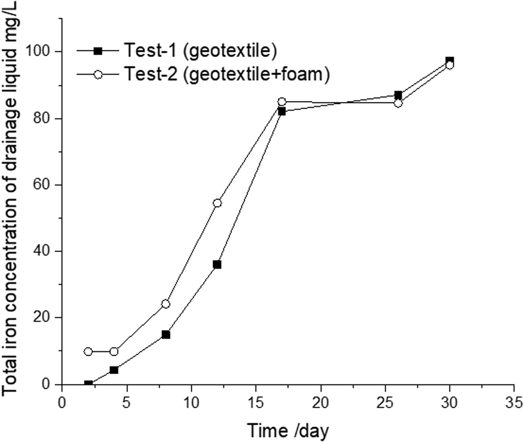
The total iron concentrations in Test-1 and Test-2 were similar after 17 days, and the slope of the curve decreased, indicating that the rates of chemical reaction in the tests slowed down and differed little for Test-1 and Test-2 at the later stage of the experiment. With the development of the clogging, more and more clogging substances formed and accumulated on the filters, and this hindered the subsequent chemical reaction. Therefore, the rate of chemical reaction slowed down at the later stage of the experiment. At this time, the differences of the rates of chemical reaction among the different tests were not obvious.
Drainage capability
The overall permeability coefficient of the system (Figure 7) is a better parameter to intrinsically reflect the nature of the drainage capability of the system. It is obvious that a high concentration of Fe2+ reduced the permeability coefficient of the system at the early stage. The curves of Test-1 and Test-2 experienced a rapid decline at the early stage of the experiment and gradually stabilized over time. The permeability coefficient in Test-3 and Test-4 experienced a short-term increase and then followed with a slow decline and gradual stabilization, and the increase stage may be attributed to the rearrangement of the particle structure under seepage force. The permeability coefficients of the system in Test-3 and Test-4 changed little after 430 h, and the time for Test-1 and Test-2 was 648 h. Hence, a higher concentration of Fe2+ accelerated the chemical clogging process.
Permeability coefficient of the system in Test-1 to Test-4.
The final permeability coefficients of Test-1 and Test-3 were similar, and the final value of Test-1 was lower than the expected value, because of the serious clogging of the geotextile caused by the initial installation at the air drying state. The final value of Test-2 was 20.4% greater than that in Test-1 without a polyurethane foam, and the final value of Test-4 was 11.0% greater than that in Test-3. This indicates that the polyurethane foam increased the drainage volume of the system, as it reduced the chemical clogging of the geotextile. The polyurethane foam had a better effect of increasing the drainage volume of the system at a lower concentration of Fe2+.
Influence of hydraulic gradient
Morphology of chemical clogging
Test-5 and Test-6 were performed with a hydraulic gradient of 10 to study the influence of the hydraulic gradient on the chemical clogging. The pictures of nonwoven geotextiles and polyurethane foams after the experiment in Test-5 and Test-6 are presented in Figure 8. The distribution form of the clogging substances in the geotextiles in Test-5 was similar to that in Test-3. There was a layer of film on the regions of geotextile that came into contact with the holes of the perforated plate, while several films on the geotextile were destroyed in the process of taking it out. When there was the polyurethane foam under the geotextile in Test-6, the clogging substances were evenly distributed on the fibers of the geotextile. There were no films on the geotextile, and several regions of the geotextile had few clogging substances. Compared with the geotextile in Test-4, the chemical clogging of the geotextile in Test-6 was slighter as a whole. Because the water saturation of the polyurethane foam increased with increasing the hydraulic gradient of the system, there were fewer opportunities for the geotextile to come into contact with air, leading to a slighter clogging of geotextiles.
Nonwoven geotextiles and porous foam after the experiment in Test-5 and Test-6: (a) geotextile in Test-5; (b); geotextile in Test-6; (c) downward face of the foam in Test-6; (d) upward face of the foam in Test-6.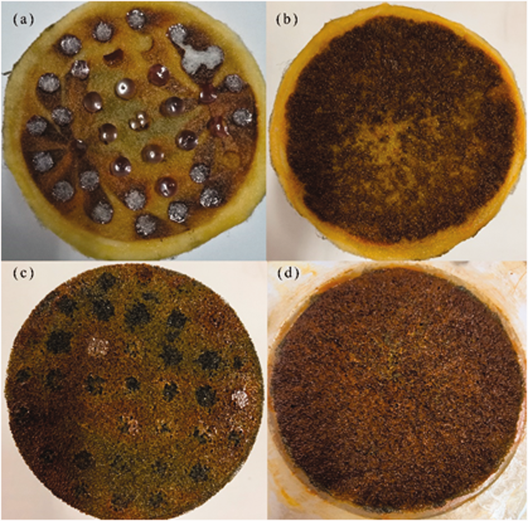
For the polyurethane foam used in Test-6, several clogging films were found on the downward face of the foam. In addition, there were more clogging substances on the foam compared to that in Test-4. On the upward face of the foam, there were a great number of clogging substances attached to the cells of the foam. However, no clogging film formed on this face. When the hydraulic gradient increased from 2.5 to 10, the flow rate of the system increased, leading to a higher water saturation of the polyurethane foam. As a result, more Fe2+ was oxidized on the foam, and the geotextile had fewer clogging substances.
Drainage capability
The permeability coefficients of the system in Test-3 to Test-6 over time are given in Figure 9. It is clear that all the curves experienced a short-term increase at the early stage of the experiment and then followed with a decline and gradual stabilization. It was quicker for the curves of Test-5 and Test-6 to enter a stable stage than those of Test-3 and Test-4. The permeability coefficient of the system with a polyurethane foam was always greater than that of the system without a polyurethane foam. The final permeability coefficient of Test-4 was 11.0% greater than that in Test-3 without a polyurethane foam, and the final value of Test-6 was 13.4% greater than that in Test-5. This shows that the polyurethane foam increased the drainage volume of the system, and this effect was more remarkable when the hydraulic gradient of the system was high.
Permeability coefficient of the system in Test-3 to Test-6.
Because when there was a polyurethane foam under the geotextile, the contact between the geotextile and outer air was reduced, which alleviated the chemical clogging of the geotextile. No films appeared on the geotextile in this case. At the same time, some of the ferrous ions were oxidized on the polyurethane foam to form clogging substances. However, compared with geotextiles, the clogging substances had less influence on the permeability of polyurethane foam due to its large porosity. Hence, as a whole, the drainage capacity of the system (geotextile and polyurethane foam) increased when there was a layer of polyurethane foam.
Long-term experiment
To study the long-term process of chemical clogging, the durations for Test-7 and Test-8 were extended to three months. In these two experiments, the width and the height of the tailings specimen were 100 mm. To provide a good permeable boundary, a wire sieve mesh and a perforated plate were placed under the geotextile in Test-7 during the experiment. The morphology of chemical clogging of the filters was similar to that in above experiments. The flow rates of the system in Test-7 and Test-8 are given in Figure 10. During the whole experiment process, the flow rate declined in a fluctuating way, and there was no sign of convergence. The flow rate of Test-8 was always greater than that in Test-7, and it was 16.7% greater than that in Test-7 at 90 days. The flow rate of Test-7 decreased from 1.7 mL/min (24 h) to 1.2 mL/min at the end of the experiment, and it only declined by 29.4%. Compared with the above tests that had a specimen of 10 mm high, the clogging extent of these two experiments was lower. Because it took more time for Fe2+ to pass through the thick specimen, many ferrous iron ions were oxidized and adsorbed in the tailings.
Flow rate of the system in Test-7 and Test-8.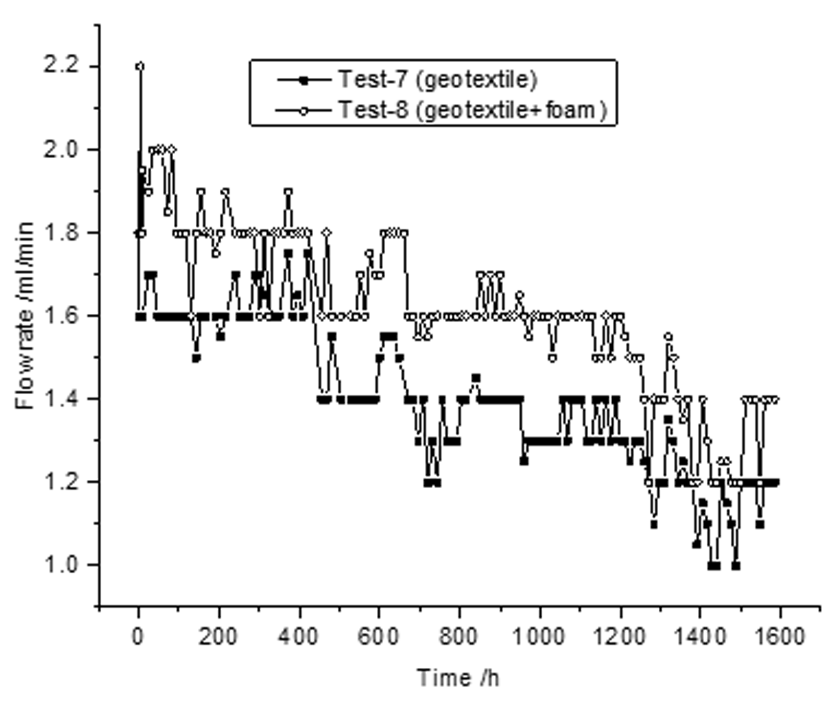
The total iron concentration of the drainage water for Test-7 was near to 0 before 25 days, indicating that the ferrous irons mainly were consumed in the tailings during this period. The value was 66.56 mg/L at 90 days, which was lower than the inputting concentration (100 mg/L). This shows that the chemical clogging was still going on at 90 days, and the thickness of the tailings specimen significantly influenced the speed of chemical clogging. The thicker the tailing specimen, the longer the chemical clogging took.
Discussion
This section discusses the mechanism of the polyurethane foam to reduce chemical clogging of the geotextile. Based on the experimental results, it is found that when there was no polyurethane foam under the geotextile, a layer of clogging film formed on the areas of the geotextile that came into contact with the holes of the perforated plate. These films blocked the water outlet of the geotextile and reduced its drainage capability. When there was a polyurethane foam under the geotextile, the chemical clogging of the geotextile was alleviated because the foam reduced the contact between the geotextile and air. A certain amount of the clogging substances were transferred to the polyurethane foam. Similarly, Zhang et al. 31 put a layer of foam outside the granular filter to address the clogging of the granular filter, and found that iron hydroxide was mainly concentrated in the foam instead of the granular filter by indoor experiment. However, geotextiles were not considered in this research. There was only a certain quantity of clogging substances that were attached to the fibers of the geotextile, and no films appeared on the geotextile. At the same time, the drainage volume of the system increased. With the increase of the concentration of Fe2+ there still were no films on the geotextile, although the clogging substances on the geotextile and the polyurethane foam increased.
Kong and Chen 32 conducted a preliminary study on chemical clogging of the geotextile in Wushan copper mine through laboratory experiments, and found that the adherence of ferric hydroxide gel to the fiber of the geotextile was the main mechanism of chemical clogging. In addition, it was observed that it was a necessary condition for a serious chemical clogging of geotextiles that the geotextiles were located in the unsaturated seepage zone. McIsaac and Rowe 13 reported the results obtained after 6 years of operation of nine mesocosm experiments that simulate the 50 cm of the drainage layer closest to the leachate collection pipe in a landfill. They found that chemical clogging on a nonwoven geotextile caused a reduction of hydraulic conductivity by about 90%. However, no polyurethane foam was considered in these two studies.
When the hydraulic gradient was low, the chemical clogging of the polyurethane foam developed from the face of the foam that came into contact with the geotextile and gradually developed outwards, and there was no film on the surface of the foam. Because the drainage volume of the system was small and the water saturation of the foam was low in this case, the air passed through the foam and arrived at its upward face. With the required condition of oxygen, the chemical clogging started at the upward face of the foam and gradually developed outwards.
When the concentrations of Fe2+ was 1000 mg/L and the hydraulic gradient of the system were 2.5 and 10, the permeability coefficients of the system with a polyurethane foam were 11.0% and 13.4% greater than that without a foam, respectively. When the hydraulic gradient was high, the polyurethane foam had a better effect of increasing the drainage volume of the system. With the increase of the hydraulic gradient, the drainage volume of the system increased and the water saturation of the foam increased; hence, there were fewer chances for the geotextile to come into contact with air. As a result, the extent of chemical clogging of the geotextile further reduced, based on Figure 8, and several clogging films appeared on the downstream surface of the foam. A high water saturation of the polyurethane foam would help to alleviate the chemical clogging of the geotextile.
It was verified that the mechanism of the polyurethane foam to reduce the chemical clogging of the geotextile was through isolating air but allowing water. The process of the chemical clogging of the geotextile was impeded by the lack of oxygen. Therefore, the factors that affect polyurethane foam permeability, such as equivalent aperture and water saturation, would have an important influence on its ability to reduce the chemical clogging of the geotextiles, and these factors should be studied in the future to further enhance the foam performance.
Conclusions
To reduce the chemical clogging of nonwoven geotextiles and enhance its drainage capability, a polyurethane foam was innovatively placed under the nonwoven geotextiles. A series of column tests were conducted to examine the influence of the polyurethane foam on chemical clogging of nonwoven geotextiles. The following conclusions are drawn.
When there was no polyurethane foam under the geotextile, a layer of clogging film covered the region of the geotextile that came into contact with air with the development of the chemical clogging. These films blocked the water outlet of the geotextile and reduced its drainage capability. A less chemical clogging of geotextiles caused by the polyurethane foam was observed and the related mechanism was firstly explained. When there was a polyurethane foam under the geotextile, the extent of the chemical clogging of the geotextile reduced due to the fewer opportunities to come into contact with air, and no films appeared on the geotextile. The drainage capability of the system increased.
When the hydraulic gradient was lower than 2.5, the chemical clogging of the polyurethane foam started at the face of the foam that came into contact with geotextile and gradually developed outward, and there were no films on the surface of the foam. Because the drainage volume of the system was small and the water saturation of foam was low in this case, the air passed through the foam and arrived at its upward face. When the hydraulic gradient increased to 10, the water saturation of the foam increased, and several clogging films appeared on the downstream surface of the foam. At the same time, the extent of chemical clogging of the geotextile reduced, as there were fewer chances for the geotextile to come into contact with air. A high water saturation of the polyurethane foam would help to a reduce the extent of the chemical clogging of the geotextile.
With the increase of the concentration of ferrous iron, the degree of the chemical clogging of the geotextile and the polyurethane foam both increased. When the hydraulic gradient of the system was 2.5 and the concentrations of Fe2+ were 100 and 1000 mg/L, the permeability coefficients of the system with polyurethane foam were 20.4% and 11.0% greater than that without a foam, respectively. The polyurethane foam had a better effect of increasing the drainage volume of the system a lower concentration of Fe2+. The thicker the tailing specimen, the longer the chemical clogging of the geotextile and polyurethane foam filters took.
Footnotes
Availability of data and material
Some or all data, models or code that support the findings of this study are available from the corresponding author upon reasonable request.
Declaration of conflicting interests
The authors declared no potential conflicts of interest with respect to the research, authorship, and/or publication of this article.
Funding
The authors disclosed receipt of the following financial support for the research, authorship and/or publication of this article: This work was supported by the National Natural Science Foundation of China (Grant No. 51609069) and the Fundamental Research Funds for the Central Universities (Grant No. 2018B04914).