
Abstract
A systematic study of a modified drafting system based on the ring spinning frame, which is called the SDS (soft drafting system), is reported in this article to raise yarn quality. Two parts of an experiment were conducted to investigate differences between the conventional and modified drafting systems by spinning three kinds of yarns (in part I) and the effects of process parameters (block gauge, pressure on the front rollers and break draft) on the SDS by using response surface methodology (RSM) to spin 18.2 tex cotton yarn (in part II). The results show that the SDS can significantly improve yarn evenness and reduce yarn imperfections of thick places by +35% and +50%, respectively, and neps by +140% per km. In addition, it is noted that the three parameters are all statistically significant for the SDS to spin yarns, while interactions between them are not. More importantly, RSM predicted a minimum CVm% of 13.95% under the optimum conditions of 1.75 mm, 190 N and 1.21 for the block gauge, pressure on the front rollers and break draft, respectively, which is very close to the conditions of the practical spinning test.
Keywords
Drafting is one of the main functions in the spinning process where the roving is drawn and lengthened. Its purposes are to make fiber strands thinner, to orient the fibers and to eliminate hooks of fibers. Due to the randomness of the floating fibers, drafting will inevitably lead to an increase in yarn unevenness. Earlier works1–4 suggested that the drafting unit is highly significant in terms of yarn quality.
From the 1960s to the present, the representative drafting devices of modern spinning frames are the SKF drafting system, Suessen HP drafting system, Rieter R2P drafting system, INA-V drafting system and FA500 series drafting system of China. 5 These conventional double-apron drafting arrangements, without exception, are still used on ring spinning machines in short-staple spinning mills. Most new ring spinning technologies have made little change in the drafting frame, such as Siro spinning, 6 compact spinning, 7 solo spinning 8 and low-torque spinning. 9 Guo et al. 10 introduced a double-channel spinning frame to produce two-color yarn. Previous researches on spinning frames have been aimed at twisting spun yarns11–14 and improvement based on the conventional drafting system (CDS).15,16 In the CDS, the elastic nip composed of double rubber aprons has the function of automatically adjusting the tension of the aprons, which can buffer the pressure fluctuations of the roller nip, which serves the elastic control of fiber bundles. However, (1) the structure of the double-apron drafting device limits the potential for shortening the front floating area, which is the main measure to improve yarn quality, and (2) the spinning speeds of the top and bottom aprons are unstable and the slip rate between them is large, which will cause fiber delamination and lead to an increase in yarn unevenness.17,18 As the use time and the speed of the spinning frame increase, static electricity, which can cause flying fibers and increase harmful hairiness, easily occurs between the two aprons.
To avoid the above situations, Ni 19 suggested that new and old aprons be used together to provide a buffer period for the changes in the apron structure, which is beneficial to prolong the service life and the best spinning period. Cheng 20 proposed a form of condensed spinning, in which the top and bottom rubber aprons are removed, to get rid of the yarn unevenness caused by the difference in speed between the aprons. This paper introduces a new drafting system, the soft drafting system (SDS), based on ring spinning machines. In experiment part I, three kinds of yarns were produced using the conventional and modified drafting systems and the spinning results were analyzed to investigate the difference between them and the applicability of the SDS. In experiment part II, response surface methodology (RSM) was successfully employed to study systematically the effects of system parameters (block gauge, pressure on the top roller and break draft) on yarn evenness.21,22
Soft drafting system
The SDS in Figure 1, without double aprons and pins, is different from the conventional one. A flexible lattice apron and two magnetically fixed curved plates are used to form the curve-shaped channel shown in Figure 1(a), so as to control the movement of fibers. With the structural change, operations, cleaning and maintenance for workers have changed greatly in spinning mills.23,24
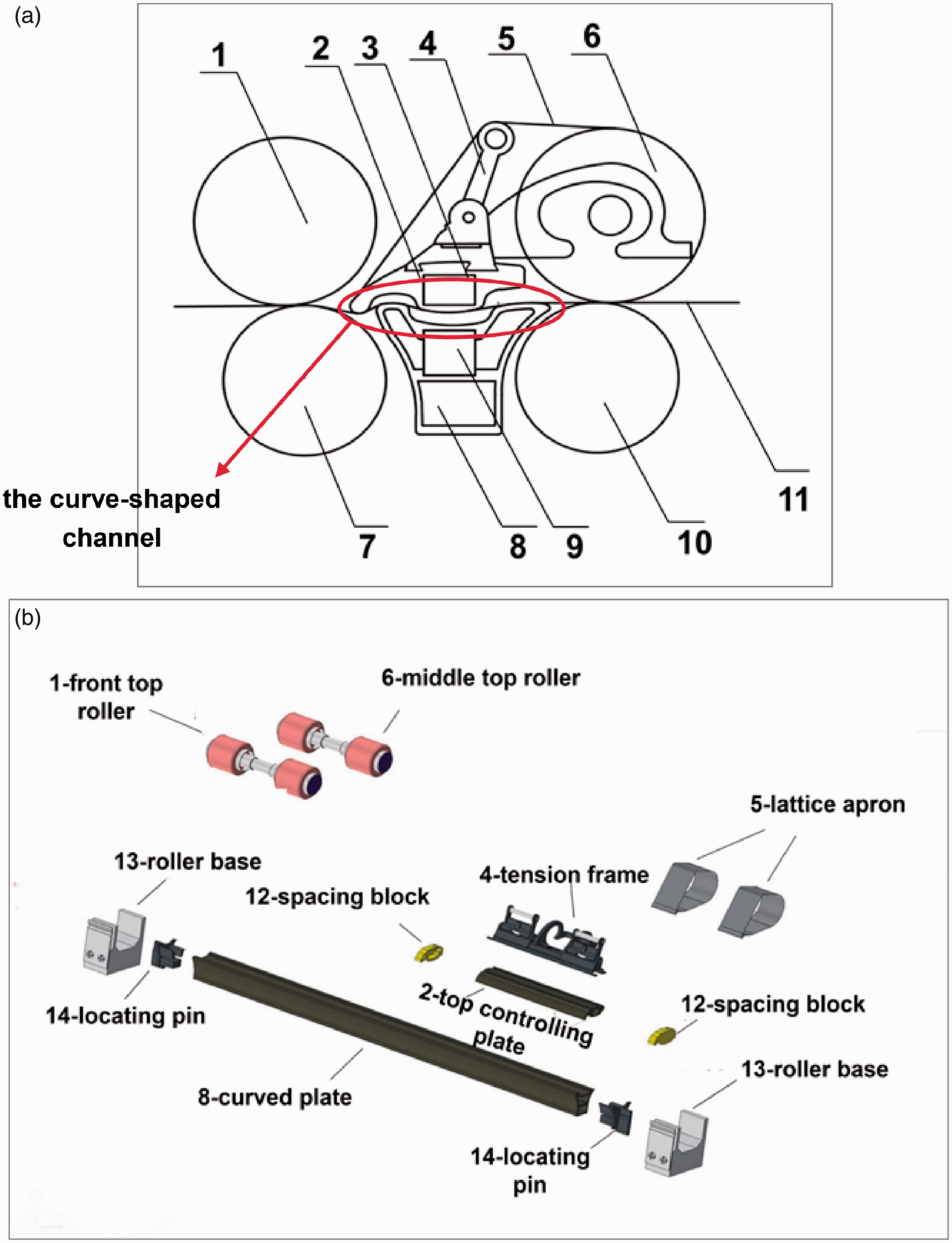
(a) Side view and (b) schematic of the soft drafting system based on ring spinning: (1) front top roller; (2) top controlling plate; (3) top permanent magnet; (4) tension frame; (5) lattice apron; (6) middle top roller; (7) front roller; (8) curved plate; (9) bottom permanent magnet; (10) middle roller; (11) roving; (12) spacing block; (13) roller base; (14) locating pin.
The center shaft of the middle top roller (6) is equipped with the tension frame (4) in which the front is the top controlling plate (2). The bottom curved plate (8) corresponding to the top controlling plate (2) is located between the front roller (7) and the middle roller (10). Two spacing blocks (12) are respectively placed on both sides of the top controlling plate to form the fixed space of the clamp, and the magnetic force between permanent magnets (3) and (9) guarantees the stability of the channel. The material of the top controlling plate and the curved plate is a hard anodized aluminum alloy that can increase corrosion resistance and improve lubrication of the two plates. The lattice apron (5) is set on the outer peripheral surfaces of the tension frame (4), middle top roller (6) and top controlling plate (2). The lattice apron is made of nylon and treated by antistatic carbon, and the size is 23.5 mm × 145 mm with 140 meshes. The lattice apron rotates with the middle roller and drags the roving through the curved plate to the front roller. The permanent magnets are NdFeB magnets with induction of more than 3500 Gs. The maximum interaction force between the magnets can reach 42.4 N, which is very stable for drafting.
The structures of the conventional double-apron drafting system and the SDS are displayed in Figure 2. It can be seen from Figure 2(a) that the main drafting zone of the conventional system is a plane drafting, while the main drafting zone of the SDS, shown in Figure 2(b), is curved drafting. The front edge marked with a red circle acts like a pressure bar, which can effectively shorten the length of the floating area in the main drafting zone. The length of the soft floating area is approximately 6 mm, which is much smaller than that of the CDS, which is about 12–14 mm.
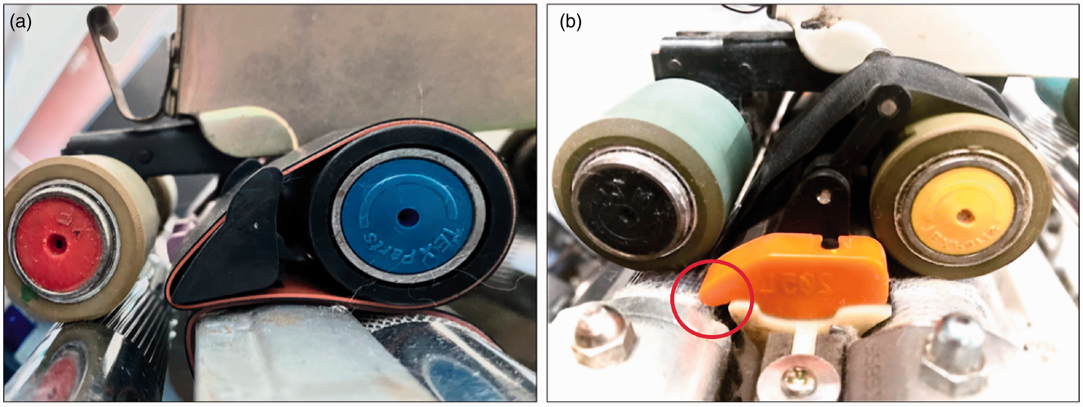
Contrast diagram of the structure of the main drafting zone of (a) the conventional drafting system and (b) the soft drafting system. (Color online only.)
The structure of the front edge applies normal pressure to the fibers in motion and changes the direction of motion, thereby strengthening the friction area of the drafting zone. Herein, it achieves the purpose of delaying slow fibers accelerating. The accelerating point of the new device is more concentrated. The features of this drafting system are that the conventional double rubber apron drive is changed to a single lattice apron drive, and the hard grip of the roving becomes a soft draft, avoiding defects of the double-apron elastic nip.
Drafting mechanism
In the modified drafting system, the top controlling plate, the bottom curved plate and the lattice apron form a stable “waveform” curved channel with a magnetic force between the spacing blocks, in which fibers are pressed by the top controlling plate through the lattice apron to the bottom curved plate. In the curved channel, since the lattice apron is thinner and has better flexibility than the traditional apron, when the convex portion of the top controlling plate is pressed, the lattice apron will deform with the curvature of the convex portion and be tensioned. Depending on the tension, fibers between the lattice apron and the bottom curved plate are stably controlled. The lattice apron can also adjust the tension slightly according to the volumes of fiber bundles under the adjustment of the tension frame, so the fiber bundles can be held softly.
A schematic diagram of the soft drafting principle is shown in Figure 3.
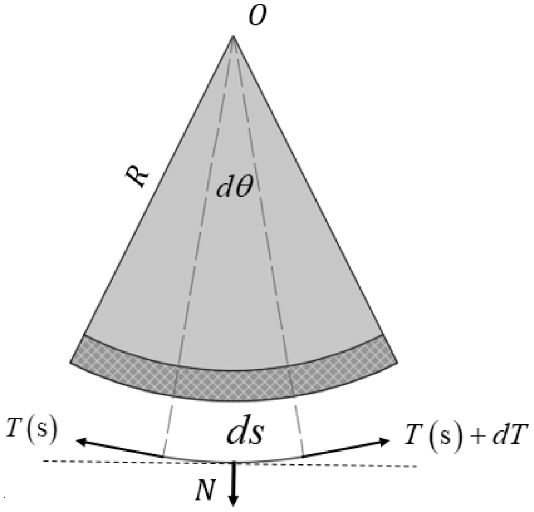
Schematic diagram of the soft drafting principle.
The radius of the lattice apron is

So

In a certain arc of the curve

So


Substituting

Equation (4)
Experiments
The experiments consist of two parts to explore the difference between the SDS and the CDC and the applicability to different raw materials, and to investigate the influence of process parameters on yarns using the RSM based on the central composite design (CCD).25,26 In part I, three kinds of yarns were spun by the two drafting systems to compare. In part II, 18.2 tex cotton yarns were produced with different parameter settings of the SDS, including the block gauge, pressure on the front rollers and the break draft. 22
Experiments: part I
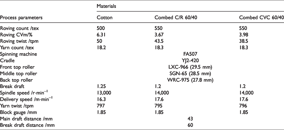
Three kinds of roving, listed in Table 1, were used for the spinning process to analyze yarn properties. The fiber parameters are listed in Table 2. Combed C/R 60/40 is the blended yarn with 60% combed cotton fibers and 40% rayon fibers, and combed CVC 60/40 is the blended yarn with 60% combed cotton fibers and 40% polyester fibers. Since the fibers of the three yarns are different and the parameters of drafting process are set according to the characteristics and length of fibers, spindle speeds, break drafts and roving counts are not all the same among the three yarns.
Spinning particulars of the two drafting systems in part I
Fiber parameters

Note: the micronaire value of cotton fibers is 4.7.
For comparison, each kind of yarn was produced on the same spindles and in the same condition to eliminate any possible variation between spindles, and the test results were analyzed statistically to determine any significant differences. The specific spinning process parameters, selected based on the CDS and preliminary experiments, are shown in Table 1.
Experiments: part II
In part II, experiments were conducted on the same machine as in part I to produce 100% cotton yarns of 18.2 tex with different block gauges, pressures on the top roller and break drafts, which are important conditions in spinning. The roving count was 500 tex and the mean value of roving CVm% was 6.42%. The experimental design was analyzed using Design-Expert 10 software.
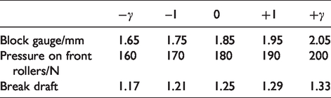
The design matrix requires a 23 factorial design augmented by six axial points. In this work, γ is the distance of axial points from the center and is equal to 1.682. The value of γ was obtained by the following equation
27

where Y is the estimated response;
The ranges of different parameters
Testing program
Before testing the yarn properties, the yarns were conditioned for at least 24 hours in standard atmospheric conditions (temperature: 20 ± 2°C, relative humidity: 65 ± 2%).
Yarn variation in mass (CVm%), yarn imperfections and hairiness were measured on an USTER® ME100 according to the ASTM D1425/D1425M-14(2020) standard. Ten samples were tested and then the average values were recorded. The testing speed was 400 m/min, and the duration time was 1 minute. The yarn tenacity was measured on the USTER® TENSORAPID and each sample was tested three times according to the ASTM D2256/D2256M-10(2015) standard.
Results and analysis
Part I: comparison of yarn properties between soft and conventional drafting systems
Combed C/R 60/40, combed CVC 60/40 and carded cotton, the three most widely used materials on the market, were spun on both drafting systems. The test results of yarn properties are given in Figures 4–9 and the statistical analysis results are listed in Table 4.
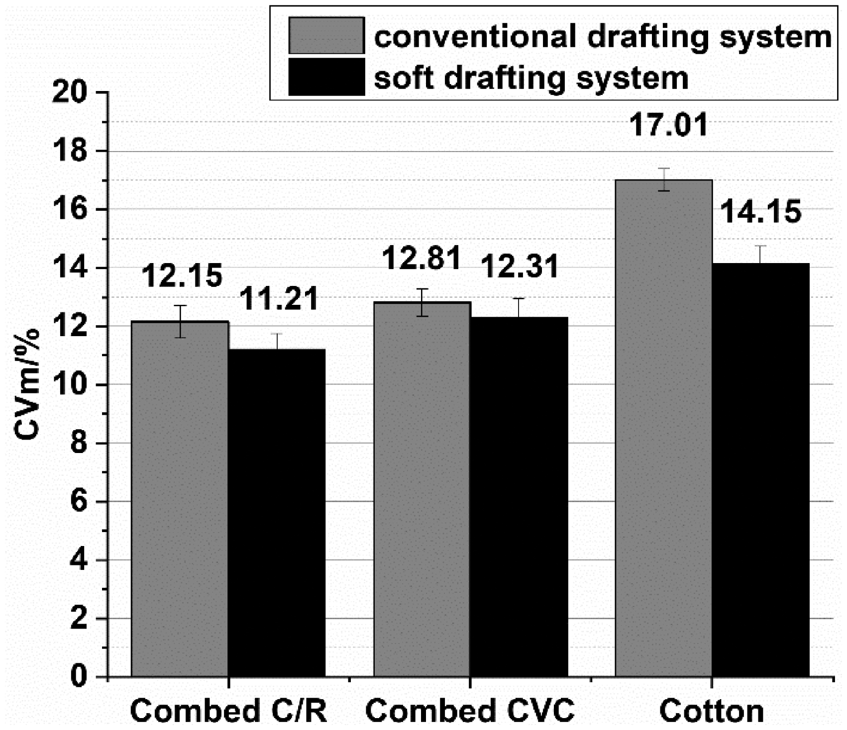
Yarn evenness values.
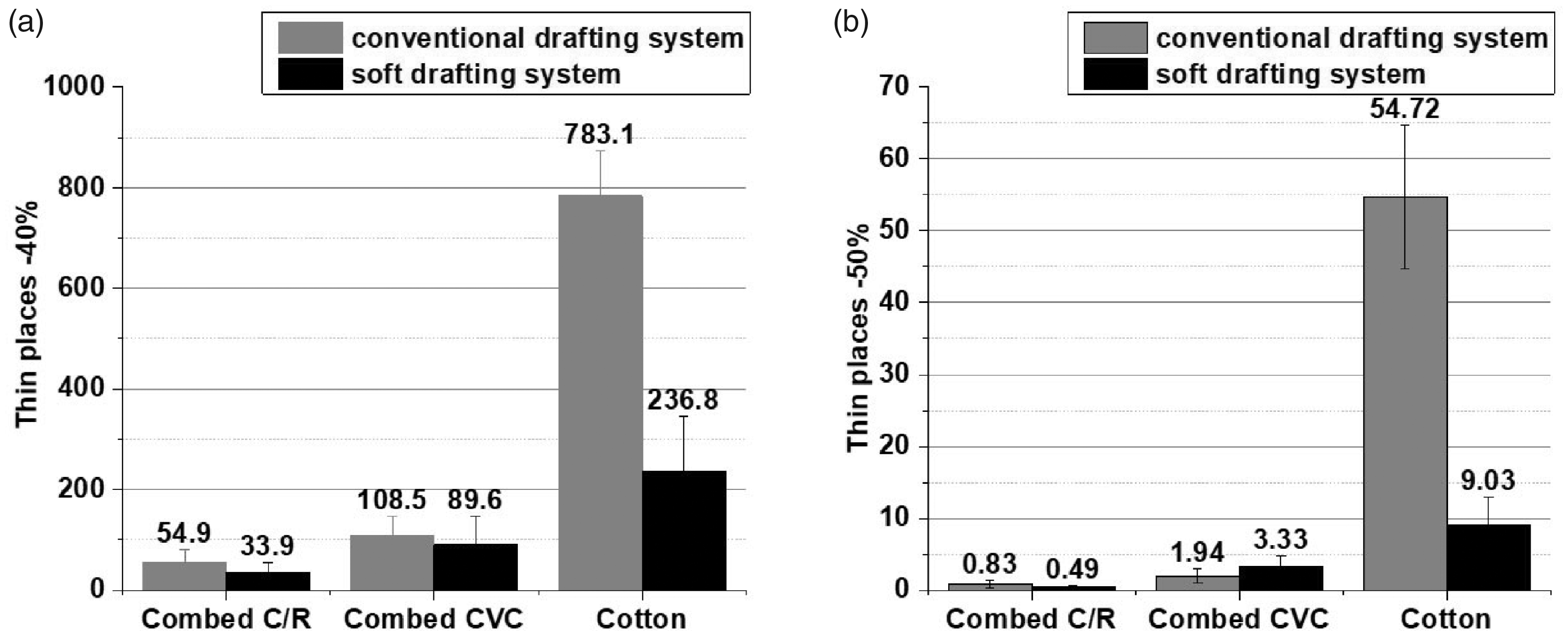
Thin place values.
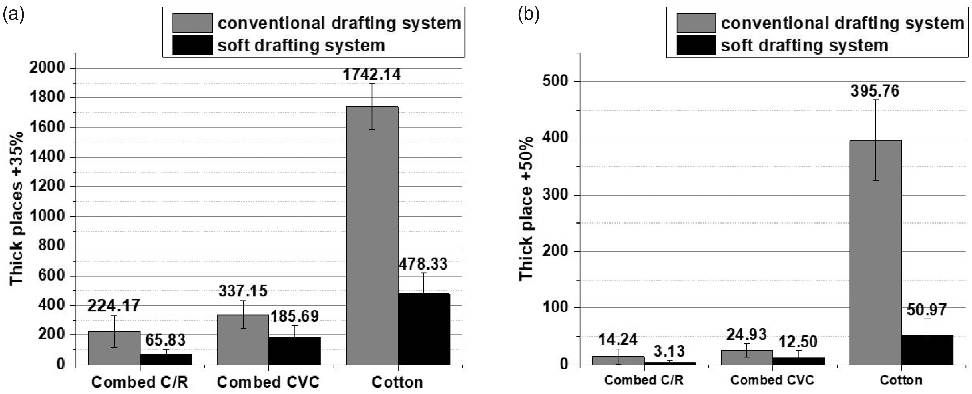
Thick place values.
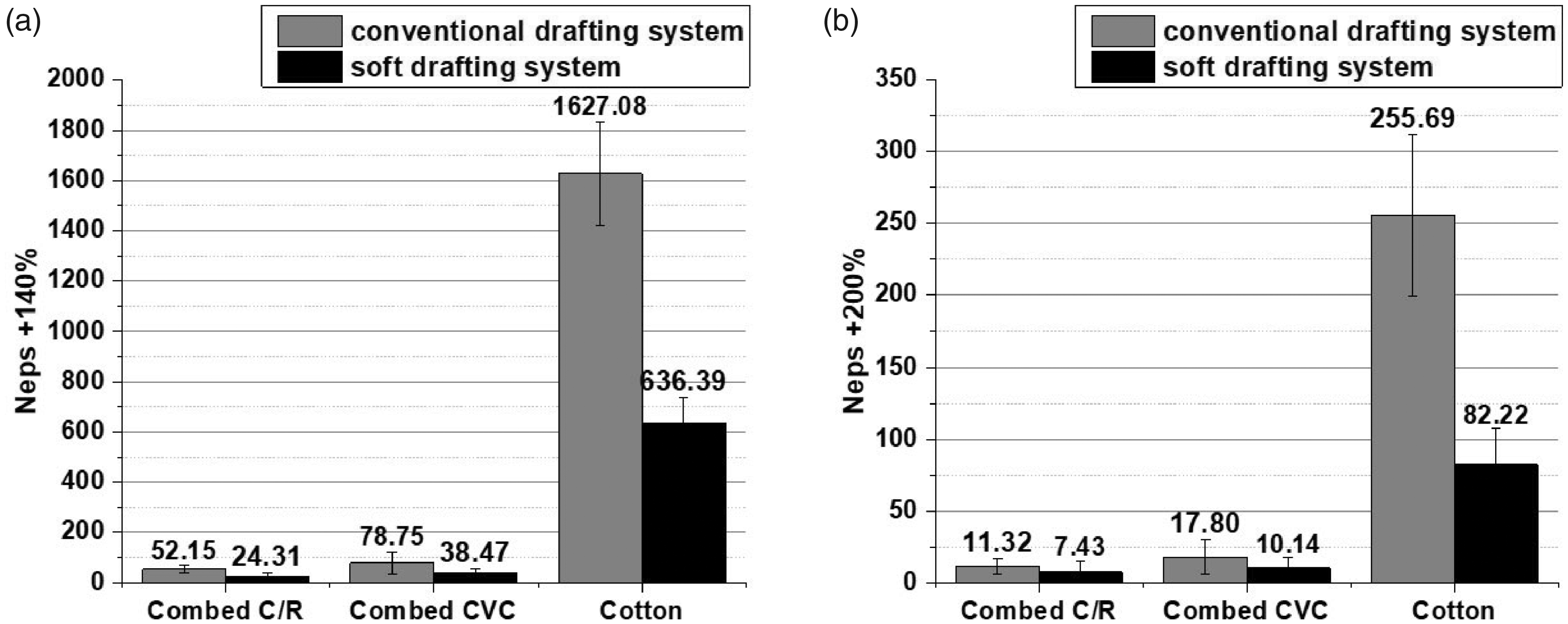
Nep values.
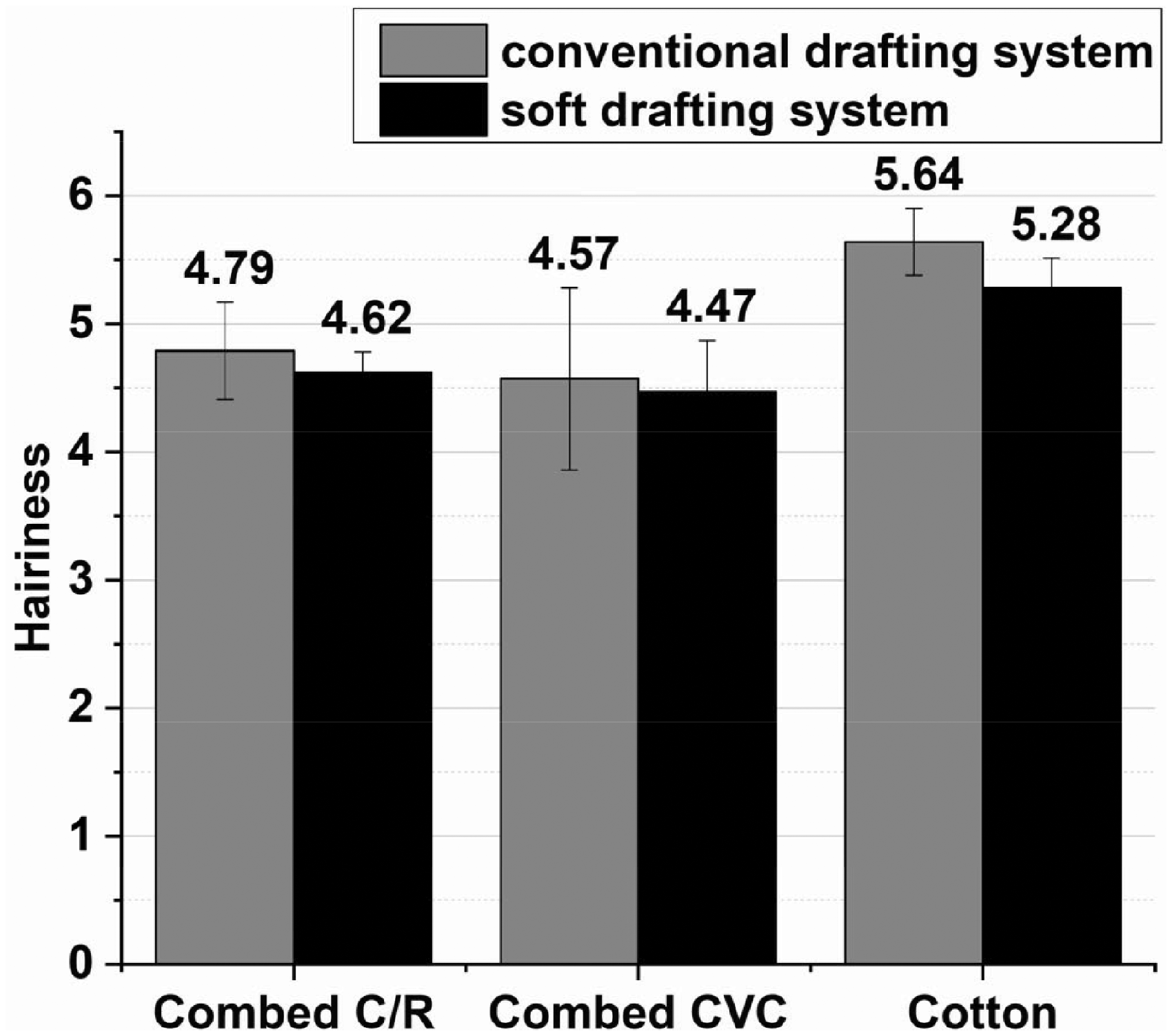
USTER hairiness (H) values.
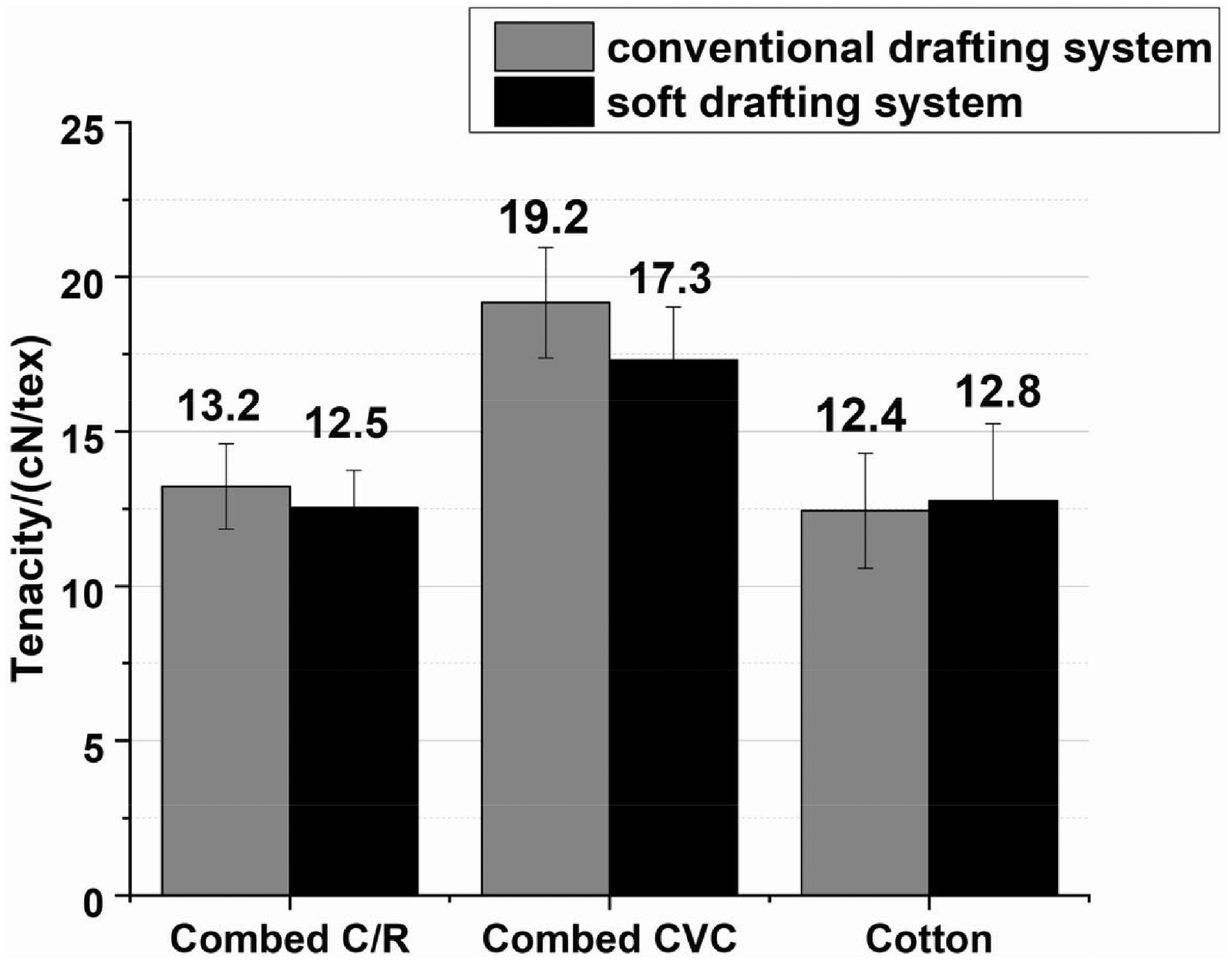
Yarn tenacity values.
The statistical analysis for the mean values of frequently occurring yarn faults produced by conventional and soft drafting methods
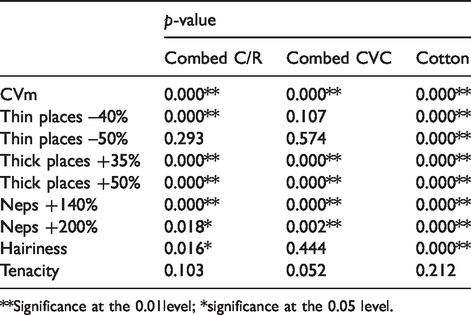
**Significance at the 0.01level; *significance at the 0.05 level.
It is noted in Table 4 that the p-values of yarn evenness are all smaller than 0.01, which means that the SDS can decrease yarn irregularity (listed in Figure 4) significantly, especially for CVm% of cotton yarn, reducing to 16.8%. The irregularity of cotton-fiber lengths, convolution structure of cotton fibers 29 and rovings not being combed lead to the cotton fibers, especially short fibers, randomly arranging and entangling in the yarn. Since the floating area of the SDS is much smaller than that of the CDS and the pressure distribution of the SDS is stable, the SDS can strengthen the control of these random short fibers to ensure the shift points of fibers are more concentrated.
Yarn imperfections (thin places, thick places and neps) are shown in Figures 5–7.
Similar to the irregularity results, all yarn samples produced on the SDS have fewer imperfections, especially in imperfections of thick places of +35% (Figure 6(a)), thick places of +50% (Figure 6(b)) and neps of +140% (Figure 7(a)), whose p-values are all less than 0.01. The values of thick places of +35% produced on the SDS reduce by 70.7%, 44.9% and 72.5% compared with those of the CDS. However, yarn properties vary with different fibers. The SDS has significant improvement in all indicators of cotton yarns, while there is no significant difference for combed C/R yarn in thin places of –50% and combed CVC yarn in thin places of –40% (Figure 5(a)) and thin places of –50% (Figure 5(b)). In the spinning process, thin places are mainly caused by accidental drafting of short fibers in the floating area, so the number of thin places in the carded cotton yarns is relatively large. However, because the floating area of the SDS is only 6 mm and fibers in motion are controlled under the normal pressure of the front edge of the SDS, accidental drafting is less likely to happen. Consequently, thin places of the cotton yarn are significantly reduced. Instead, for combed yarn, there are fewer short fibers after the combing process, so the front drafting part (SDS or CDS) has little influence on the imperfections of thin places, especially on the –50% thin places.
The USTER hairiness (H) results of three yarns are given in Figure 8. Although it is just a slight reduction in hairiness for combed CVC, the SDS can reduce the hairiness of combed C/R and cotton yarns significantly. In the ring spinning frame, the hairiness is mainly produced in the process of twisting and winding after drafting. Firstly, in the twisting triangle, a large number of fiber ends and a few fiber middle sections, which are not controlled by the twisting torque, cannot be rolled into the yarn body and are exposed outside to form hairiness. Secondly, during the process of twisting and winding, yarns are rubbed by the yarn guide wires, yarn separators and ring travelers, so that some of fiber ends or fiber middle sections in the yarn body or on the surface of the yarn are scraped, rubbed and pulled out to form new hairiness. Although the control of the SDS on fibers is conducive to the concentration of the shift points of fibers and can reduce fiber diffusion, it can only slightly reduce the amount of hairiness due to the mechanism of hairiness generation.
The yarn tenacity test results are shown in Figure 9. Combined with Table 4, it is observed that tenacity of the SDS yarns of combed C/R and combed CVC are slightly lower than that of the control samples, while the tenacity of the cotton yarn has increased. For the combed yarns, this is due to the improvement in fiber straightness after the SDS, which leads to the deterioration of cohesive forces between fibers, resulting in a decrease in the yarn tenacity. However, it can be seen from Table 4 that the differences are not statistically significant for any of the three kinds of yarns. Hence, the SDS has little effect on yarn tenacity.
From the above results, the SDS has huge advantages in terms of yarn evenness and imperfections.
Part II: evenness of yarns produced on the soft drafting system with different particulars
CVm% is the main indicator of yarn evenness reflecting the drafting process. Therefore, this part takes CVm% as the test indicator. The relationships between yarn evenness and the three independent variables (block gauge, pressure on the front rollers and break draft) were studied. The experiment design of CCD shown in Table 5 also provides the test results for each experimental run.
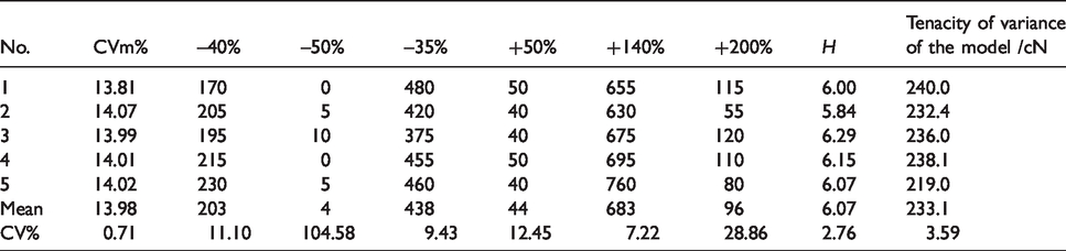
Experimental design matrix and yarn evenness

The regression equation based on the second-order polynomial model was obtained to assess the influence of the three parameters on the yarn evenness. The concluding relation can be expressed as follows

In this equation, the negative and positive signs in front of the factors demonstrate antagonistic and synergistic effects, respectively. The determination coefficient (
The parameters, such as the p-value, F-value and
Analysis of variance of the model equation

As shown in Figure 10, contour plots can express the combined effects of two factors on the yarn irregularity when the other factor is maintained at the center level.

Response surface plots and the corresponding contour plot for interactive effect among factors ((a) block gauge and pressure on the front rollers; (b) block gauge and break draft; (c) pressure on the front rollers and break draft) on yarn evenness CVm%.
Figure 10(a) describes the interaction between the block gauge and pressure on the front rollers with the break draft of 1.25. At a pressure of 160 N, CVm% increased by 0.21%. (from 15.51% to 15.72%) as the block gauge increased from 1.65 to 2.05; at a pressure of 200 N, CVm% increased by 1.88%. (from 13.86% to 15.74%) as the block gauge increased from 1.65 to 2.05. When the pressure on the front rollers is too small, it is recognized that yarn evenness becomes worse sharply due to the abnormal local slip phenomenon of the fiber bundle in the front roller nip, 25 and the block gauge has little influence on the yarn.
Figure 10(b) illustrates the individual/combined effects of the block gauge and break draft when the pressure was at zero level (180 N). For a given break draft, yarn evenness reduces as the block gauge is larger, which can be attributed to the reduction of force between the top controlling plate and bottom curved plate. As with the interaction in Figure 10(a), CVm% increases by 1.06% as the break draft increases from 1.17 to 1.33 at a block gauge of 1.65, but does not change obviously (–0.38%) at a block gauge of 2.05. The break drafting process is to untwist the roving, which is beneficial to the straightening and parallelization of fibers. There is a critical point for the break draft: excessive draft will cause unexpected drafting and increase thin places; too small a draft will cause poor untwisting.
The interaction effect of pressure on the top rollers and break draft is represented in Figure 10(c). As can be seen for each break draft, CVm% decreased as pressure on the front rollers decreased in the range of 160–190 N. Yarn evenness worsened by 0.05% and 0.01% when the pressure increased from 190 to 200 N at break drafts of 1.17 and 1.33, respectively. Excessive pressure on the rollers aggravates the load of the drafting drive system, causing side effects such as wear and roller bending, which in turn destroy the normal drafting process and affect the yarn quality. 30
The optimum condition of each variable is designated by RSM to obtain the best yarn evenness. Here, 1.75 mm, 190 N and 1.21 are the optimum conditions for the block gauge, pressure on the front rollers and break draft, respectively, where the predicted value of yarn unevenness (CVm%) is 13.95%. In the verification experiments, the CVm% of the yarn spun with the optimum conditions is 14.02%, listed in Table 7, which is very close to the predicted value.
Results of verification experiments
Conclusions and outlook
This paper introduces characteristics of the SDS and describes the principles of how and why it can improve the qualities of yarns. The yarn quality test results show that the SDS can improve yarn evenness and reduce the number of frequently occurring yarn faults. The reductions of thick places of +35% and thick places of +50% are especially significant. The analysis of the factorial experiment using RSM based on CCD indicates that the spacing block gauge, pressure on the front rollers and break draft have significant influences on the yarn evenness, while their interactions with each other do not. The second-order polynomial regression model proposed by the statistical analysis results could properly interpret the experimental data. The minimum CVm% of 13.95%, which is very close to the experimental result (CVm% = 14.02%), is predicted under the following optimal parameters: block gauge of 1.75 mm, pressure on the front rollers of 190 N and break draft of 1.21.
Through the preliminary theoretical research and experiments on the SDS, we can determine that it has certain reliability for improving yarn quality and has a wide variety of adaptability. More systematic theoretical research and detailed study will be carried out on this system in the future. A study about feasibility of the system for industrial use will also be conducted, where the factors include the stability of the device, implementation cost, energy consumption and so on.
Footnotes
Declaration of conflicting interests
The authors declared no potential conflicts of interest with respect to the research, authorship, and/or publication of this article.
Funding
The authors disclosed receipt of the following financial support for the research, authorship, and/or publication of this article: This work was supported by National Key R&D Program of China (Grant No. 2017YFB0309100), College of Textile, Donghua University, Shanghai, China.