



Abstract
Due to its excellent light-weight, mechanical, and electromagnetic performance, the three-dimensional woven spacer microstrip antenna (3DWS-MA) has become a promising communication device to be applied in aerospace or high-speed vehicles. To explore the electromagnetic performance of 3DWS-MA in extreme environments, microstrip antennas based on three-dimensional woven glass fiber/epoxy spacer composites (3DWSC) with different conductive yarn (copper wire, nickel-coated carbon yarn and carbon nanotube yarn) were manufactured and tested at various temperatures (from –196°C to 150°C). The results showed that the 3DWSC exhibited superb dielectric properties (
Keywords
The three-dimensional textile structure has great potential as a platform for highly integrated multifunctional composites, due to its multi-dimensional and embeddable features. 1 The conformal microstrip antenna based on three-dimensional textile composites is a typical example of multifunctional composites. Conformal antennas were proposed in the 1990s and were developed to realize the integration of antennas into structures for better mechanical properties.2–5 In the integration designs, the antennas were embedded in the sandwich composite structure. This sandwich structure brought excellent weight efficiency to the microstrip antenna. 6 , 7 However, when the microstrip antenna was subjected to mechanical and thermal shocks, easily delaminated, which eventually caused the antenna to malfunction.
To overcome the delamination problem, the concept of the three-dimensional integrated microstrip antenna (3DIMA) was proposed.8–11 In the 3DIMA structure, the antenna elements are woven by fibrous materials, including the conductive fiber and the reinforced fiber, into a three-dimensional orthogonal fabric using textile technology. Then, the 3DIMA is obtained by composing the three-dimensional textile antenna preform with matrix resin. However, the solid composite antenna structure brought fatal disadvantages such as poor electromagnetic radiation (gain
Three-dimensional woven space composites (3DWSCs) are hollow integrated structures with excellent light-weight, mechanical, and dielectric properties,15–19 and exhibit great application prospects in integrated multifunctional composites such as radomes and microstrip antennas (Figure 1). The three-dimensional woven spacer microstrip antenna (3DWS-MA) with excellent electromagnetic performance and ultra-low density, as well as low-profile characteristics, is very suitable for use with aerofoils or other curved structures, such as electromagnetic transmission equipment in airplanes, satellites, or high-speed vehicles. However, the dielectric properties of 3DWSC and electrical resistance of conductive fibers can be sensitive to temperature change,19–23 which may affect the electromagnetic performance of the 3DWS-MA. Therefore, the performance of 3DWS-MAs with different conductive fibers in various temperatures should be systematically investigated.
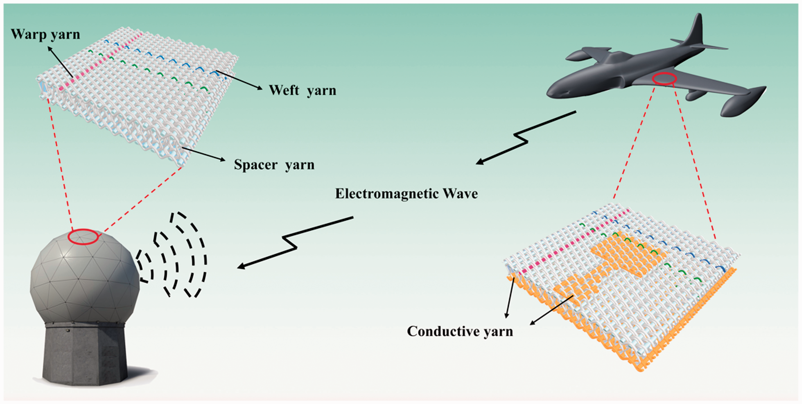
Schematic illustration of the application of three-dimensional woven space composite in radome and load-bearing microstrip antenna.
In this study, 3DWSC and the microstrip antenna with different conductive yarns (copper wire, nickel-coated carbon yarn, and carbon nanotube yarn) were manufactured and tested. The S11 values of 3DWS-MAs under different temperature conditions were characterized. To explore the principle of the change in performance of 3DWS-MAs, the dielectric properties of 3DWSC and the electrical resistance of conductive yarn were tested and analyzed. This research can provide an experimental basis for the practical application of 3DWS-MA in different scenarios.
Experiments
Materials
3DWSC was woven utilizing pure E-glass yarn (300 tex) provided by Zhejiang JuShi Group. The dielectric constant is 6.0 and the dielectric loss is 0.003. The resin system for the substrate consolidation was the epoxy resin (JL-235) and the curing agent (JH-242), supplied by Jiafa Chemical Company, China. The dielectric constant is 4.0 and the dielectric loss is 0.02. The yarn used for feeding line and ground plane were copper wire, nickel-coated carbon yarn, and carbon nanotubes (CNT) yarn. The copper wire was supplied by Lizi Precision Electric Wire Company (Wuxi, China) with the diameter of 0.4 mm. The conductivity of copper wire was
Manufacturing of 3DWSC and 3DWS-MA
The 3DWSC and 3DWS-MAs were manufactured using a self-built three-dimensional woven loom. The fabric count for both warp and weft yarns in the case of each layer and Z-yarns of 3D fabric were 5
Compression test of 3DWSC
According to the test standard of ASTM C365/C365M-11a, compression experiments were carried out through an INSTRON test machine (model 5967). These composites were prepared as a sample with a length of 40 mm×40 mm and tested along the spacer yarn direction, and the speed of the cross-head was set at 0.5 mm/min.
Dielectric properties of 3DWSC measurement
A Vector Network Analyzer (VNA) PNA3766 was used to measure the dielectric constant and dielectric loss of the composites. This test method is the resonance frequency method. The value of the dielectric constant



The diameter of the test sample is 80 mm and the height is 6 mm. The test frequency is 30 MHz–3 GHz. The dielectric properties of 3DWSC at high and low temperatures were tested in a heating oven and a cryogenic box. The samples were placed inside the box and connected to the VNA through a transmission line. Pictures of the test are shown in supplementary Figure S1.
Conductivity measurement
This experiment uses an Agilent 34450A digital multimeter to measure the resistance change of conductive yarns. The length of the copper wire and NCCF sample was 50 m, and the length of the CNT sample was 0.5 m. The sample was evenly wound on the paper tube, and the two ends of yarns were connected to the digital multimeter to measure its resistance. When measuring the resistance change at different temperatures, the paper tube wrapped with yarn was placed into the cryogenic box or heating oven. A schematic diagram is shown in supplementary Figure S2.
Antenna S-parameter measurement
For S-parameter measurement, the 3DWS-MAs were connected to a calibrated PNA3766. The return loss was measured from the S11 following the below equations:


Radiation pattern measurement
Radiation pattern measurement of 3DWS-MA was carried out in a microwave anechoic chamber as shown in supplementary Figure S3. The microwave anechoic chamber was a closed space surrounded by absorbent material (polyurethane absorbent sponge SA) to reduce the interference of external electromagnetic waves. Radiation patterns were measured by the HP 8510C Antenna Test System. The antennas rotated 360° with the turntable and transmitted a signal while an auxiliary antenna was fixed at one point receiving the signal simultaneously, and the system calculated the result of the pattern. By comparing field values of a Reference-Gain Horn Antenna, the gain of tested antenna was calculated.
Results and discussion
Dielectric properties of 3DWSC
As shown in Figure 2(a) the face sheets of 3DWSC were woven by warp and weft yarns as plain weave structure, while the core layer of 3DWSC was composed of spacer yarns. Two face sheets were connected together with “8” shaped spacer yarns being interlaced (moving up and down) along the warp direction, resulting in the high void fraction (75%) and low density (0.5 g
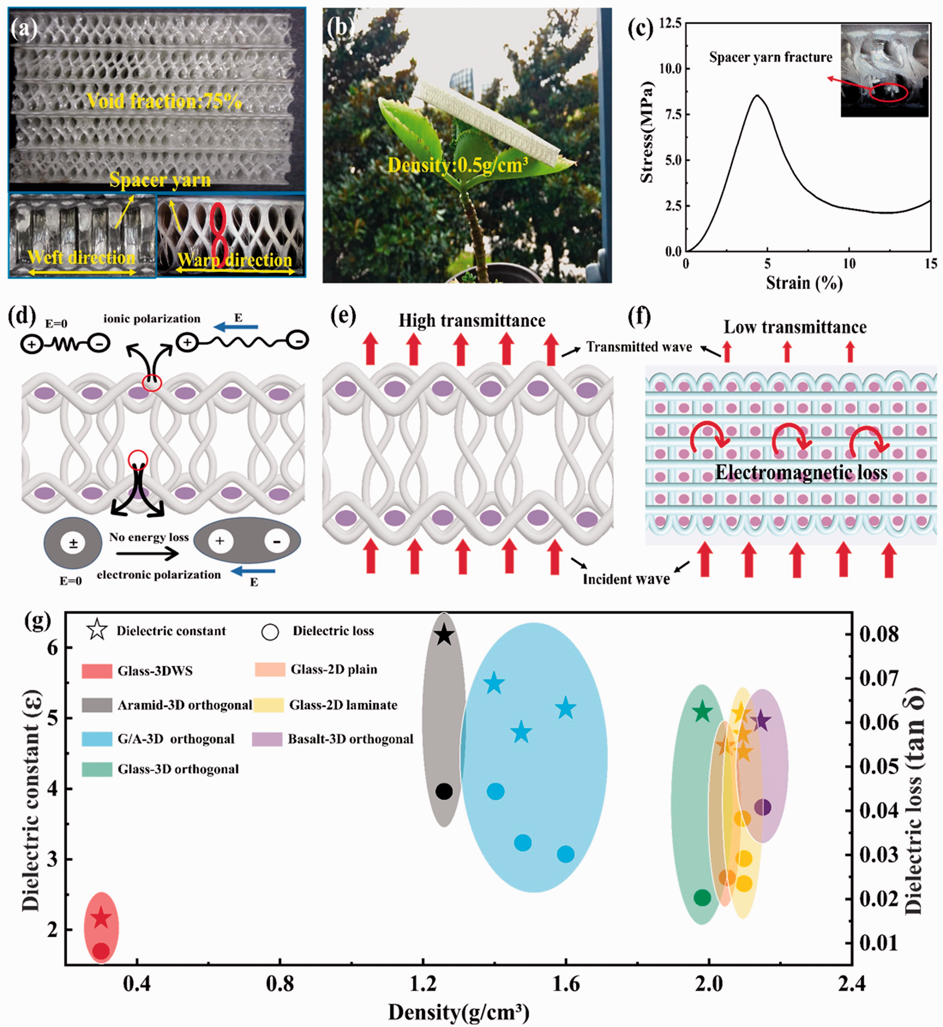
(a) optical picture, (b) light-weight characteristic, and (c) compression stress-strain curve of 3DWSC; (d) schematic illustration of polarization of 3DWSC material in electric field; (e, f) comparison of wave permeability between 3DWSC and 3D orthogonal composites; (g) comparison of density, dielectric constant, and dielectric loss with other 2D and 3D composites.
Due to the firm spacer yarns, 3DWSC exhibited superb compressive strength (8.5 MPa), as shown in Figure 2(c). Dielectric materials (resins and fibers) can be polarized under the action of an electric field, while the energy loss occurred when molecules were polarized and shaken. 28 However, most of the molecules of the air are non-polar dielectrics, which will undergo electron displacement polarization in the electric field without consuming energy, resulting in the low dielectric constant (1.62) and dielectric loss (0.016) of 3DWSC (Figure 2(d)). Compared with the solid structure of the three-dimensional composites, 3DWSC had a lower dielectric constant and dielectric loss, which can greatly reduce the reflection and loss of incident waves 1 (Figure 2(e, f)). Figure 2(g) shows the comparison of the density, dielectric constant, and dielectric loss of different types of composites. Compared with two-dimensional composites, three-dimensional laminated composites and three-dimensional orthogonal composites composed of glass fiber, aramid, and basalt fiber, the 3DWSC prepared by E-glass fiber in this experiment had the lowest density and also showed the best dielectric properties.25–30 These excellent mechanical and dielectric properties of 3DWSC endow broad potential applications in smart composites and systems.
Microstrip antenna based on 3DWSC
Figure 3(a) and 3(b) show a schematic of 3DWS fabric and microstrip antenna which comprising radiation patches, dielectric substrate, and ground plane. By combining the microstrip antenna into the 3DWS fabric structure, 3DWS-MA was proposed as shown in Figure 3(c). In 3DWS-MA, conductive yarns were embedded in the top and bottom layers as radiator patch and ground plane, integrated by spacer yarns. The main steps of the three-dimensional weaving process used are shown in Figure 3(d). First, the weft yarns were inserted into the upper and lower sheds composed of warp yarns. Then, the warp yarns were interwoven to form a plain weave. Finally, both top and bottom layers were bound by spacer yarns by interlacing (moving up and down) along the warp direction over the copper weft yarns. After several weaving cycles, the conductive warp and weft yarns were woven into certain patterns to form the radiating patch, feeding line, and ground plane of the 3DWS-MA.
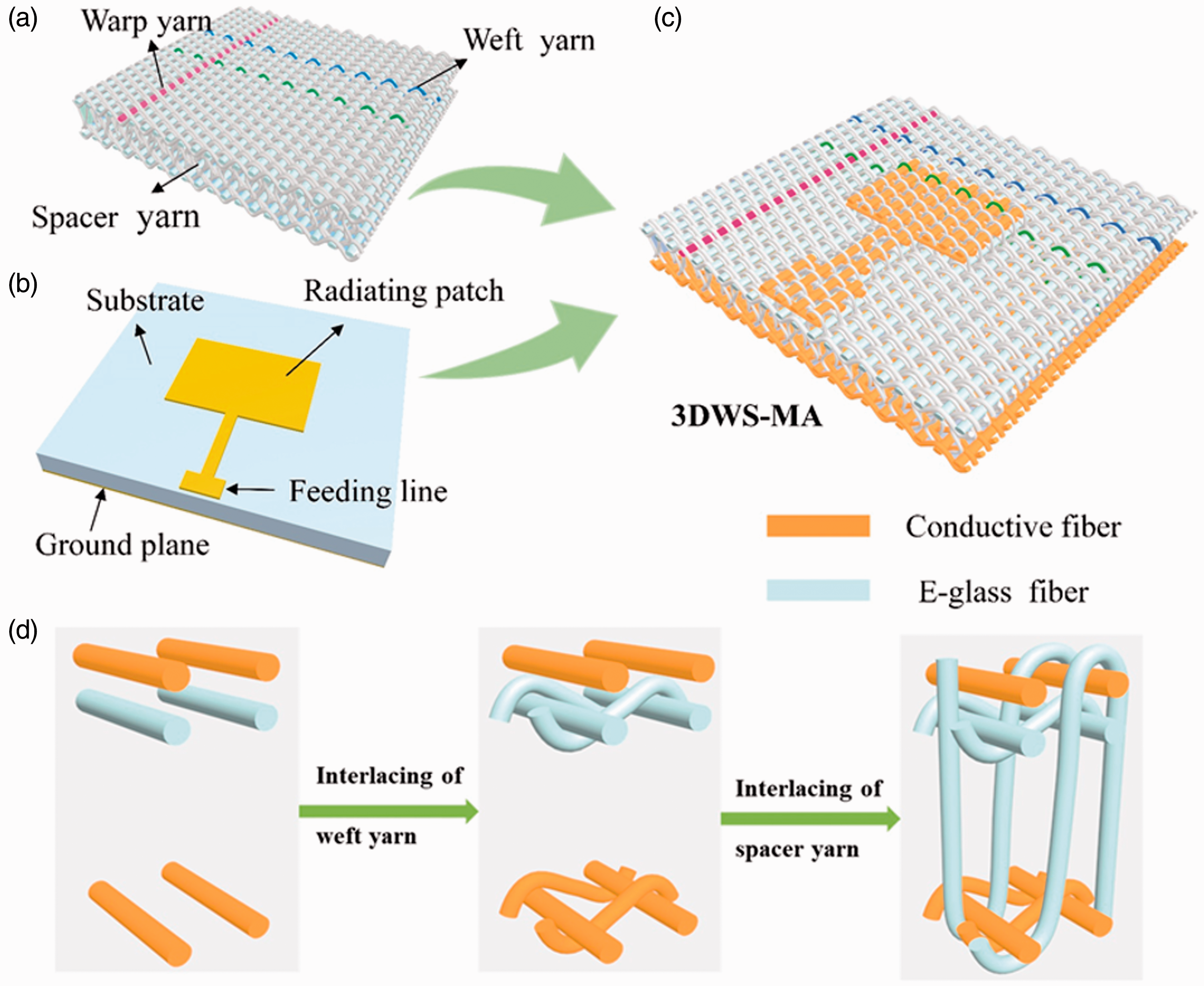
Structural schematics of (a) 3DWS fabric, (b) microstrip antenna and (c) 3DWS-MA; (d) schematic of weaving process of 3DWS-MA.
Figure 4(a) shows that the resonant frequency was near the designed frequency (2.4 GHz) of 3DWS-MA (copper) while the S11 value was lower than –23 dB. This means that at least 99% input power was delivered to the antenna, which is acceptable for most practical applications. The imbedded image in Figure 4(a) shows the optical figure of 3DWS-MA. Figure 4(b) is the radiation pattern of the E-plane, showing that the main lobe had a maximum value of 7 dB near 90°and small side lobes in other directions, which demonstrated the good radiation property of the antenna.
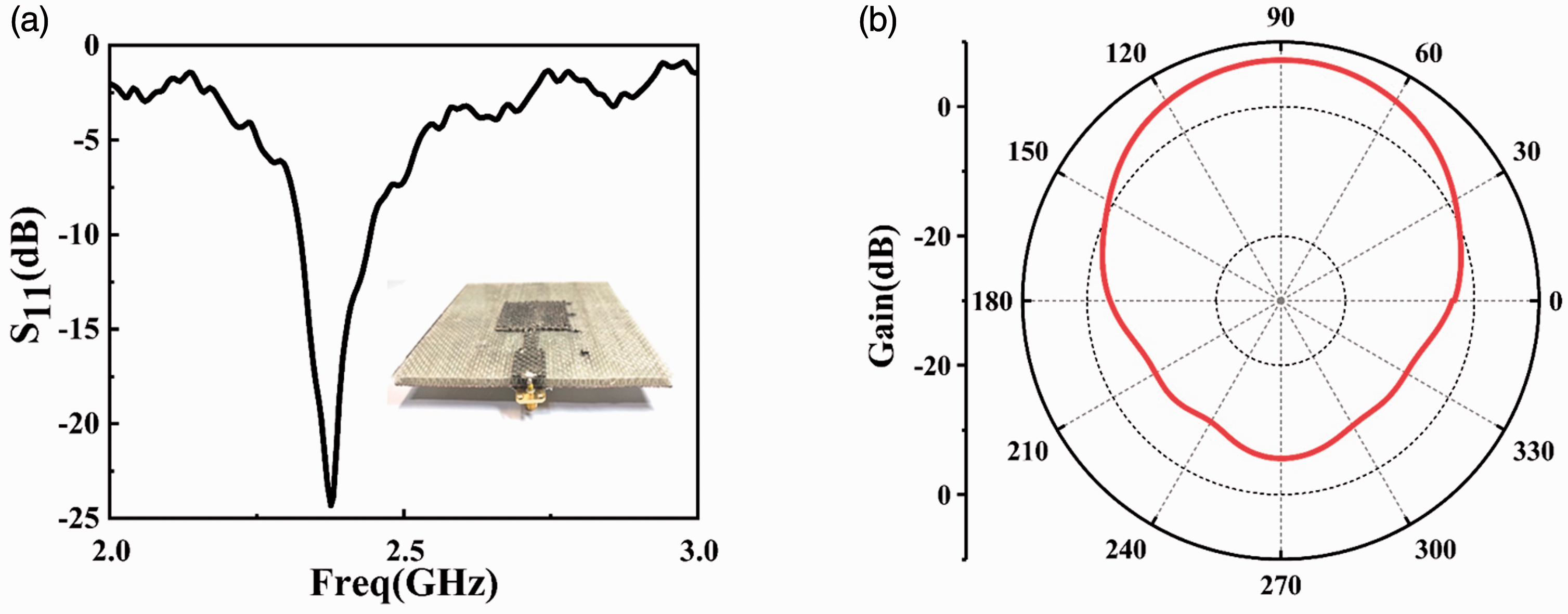
(a) S11 of 3DWS-MA; (b) E-plane radiation pattern.
Electromagnetic performance of 3DWS-MA in various temperature conditions
Figure 5(a) is a schematic diagram of 3DWS-MAs testing S11 at low temperatures from –196°C to 0°C. As shown in Figure 5(b), when the temperature increases, the S11 values of 3DWS-MA (copper) gradually decrease from –25 dB to –29 dB; simultaneously the resonant frequency decreased from 2.44 GHz to 2.40 GHz. The same trend was also observed in 3DWS-MA (carbon yarn) and 3DWS-MA (CNT yarn), as shown in Figure 5(c) and 5(d), respectively. The resonant frequency changes of the three antennas were similar (30–50 MHz), but the S11 value change of 3DWS-MA (CNT yarn) was the lowest (4 dB).

(a) test diagram at low temperature; S11 at different low temperatures of (b) 3DWS-MA (copper), (c) 3DWS-MA (carbon yarn), (d) 3DWS-MA (CNT yarn).
Figure 6(a) is a schematic diagram of 3DWS-MA testing S11 at high temperature. As shown in Figure 6(b–d), when the temperature increases from 20°C to 150°C, the resonant frequencies of the three antennas shifted to lower frequencies, and the S11 value also increased. Among them, the S11 value of 3DWS-MA (copper) was relatively stable and gradually increased from –23 dB to –19 dB, and the resonance frequency shifted from 2.40 GHz to 2.34 GHz. The resonant frequency and S11 value of 3DWS-MA (carbon yarn) changed by 50 MHz and 4 dB, respectively, but its electromagnetic performance was poor. The resonant frequency of 3DWS-MA (CNT yarn) had 40 MHz offset, but the S11 value had the highest degradations (17 dB). The electromagnetic performance of 3DWS-MA in various humidity conditions was investigated, as shown in supplementary Figure S5, and the result showed humidity had little effect on the S11 of the three types of 3DWS-MAs.
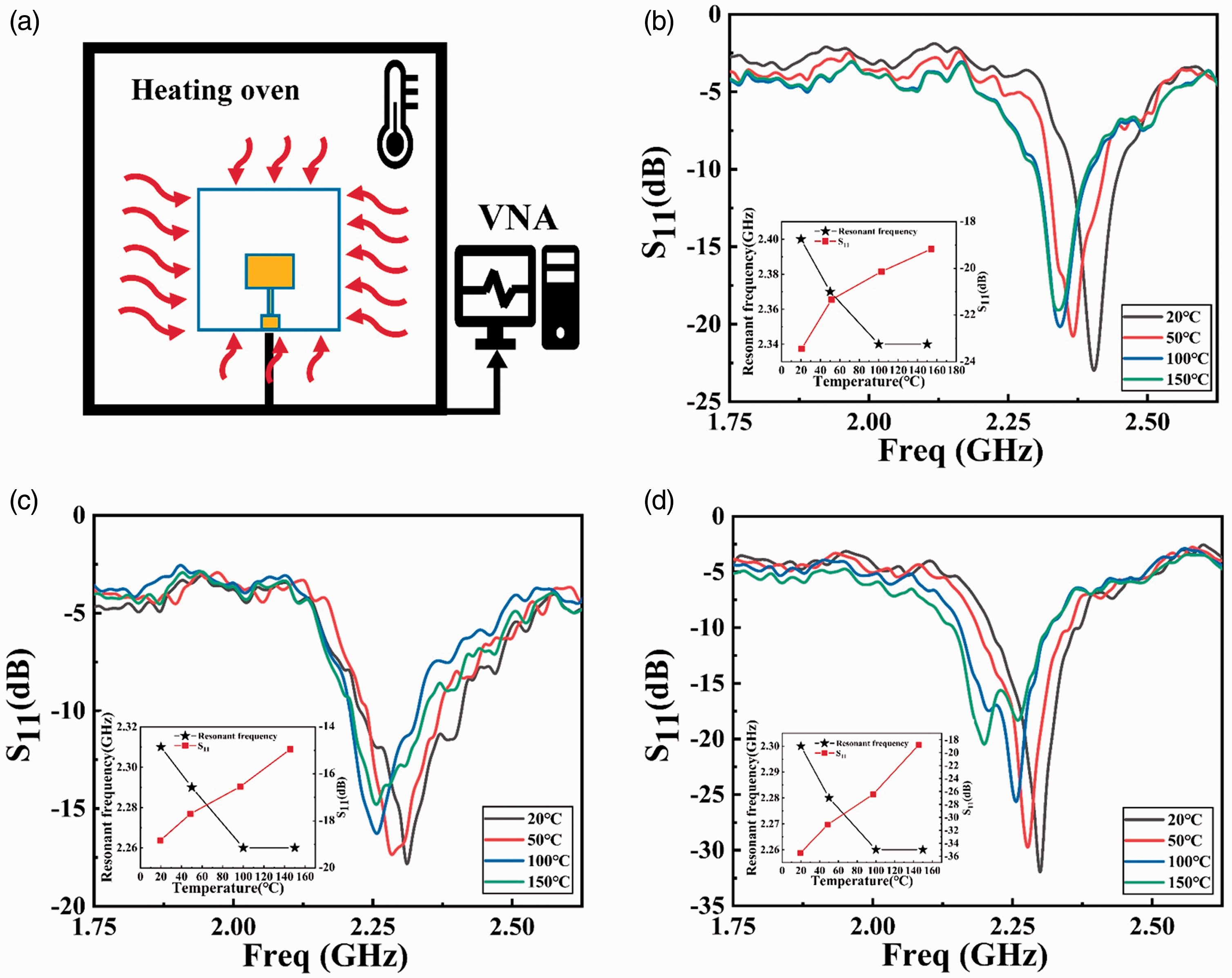
(a) test diagram at high temperature; S11 at different high temperatures of (b) 3DWS-MA (copper), (c) 3DWS-MA (carbon yarn), (d) 3DWS-MA (CNT yarn).
Property test of 3DWSC and conductive fiber in various temperature conditions
As shown in Figure 7(a), with the temperature increasing from –196°C to –100°C, the dielectric constants of 3DWSC maintained a constant (1.57). However, with the temperature rising from –100°C to 0°C, it increased from 1.57 to 1.62. The main components of E-glass fiber are SiO2, Al2O3, MgO, and B2O3, and it contains Al3+, Mg2+, and B3+. Consequently, the main polarization forms of glass fiber are electron displacement polarization and ion displacement polarization. 35 Epoxy contains a large number of polar groups such as ether bond, amine bond, and lipid bond, therefore the main polarization form of epoxy is dipolar polarization. 36 , 37 Therefore, the change in dielectric constant at –100°C to 0°C was due to the dipolar polarization of epoxy resin and ion displacement polarization of glass fiber resulting from thermal movement. Similarly, when the temperature rises from 20°C to 70°C, as shown in Figure 7(b), the dielectric constants of 3DWSC increased from 1.62 to 1.67 due to the destruction of the fiber/matrix interface and thus the increment of interfacial polarization. 38 When the temperature was higher than 70°C, the dielectric constant remained stable due to the saturation of the material polarization. 39
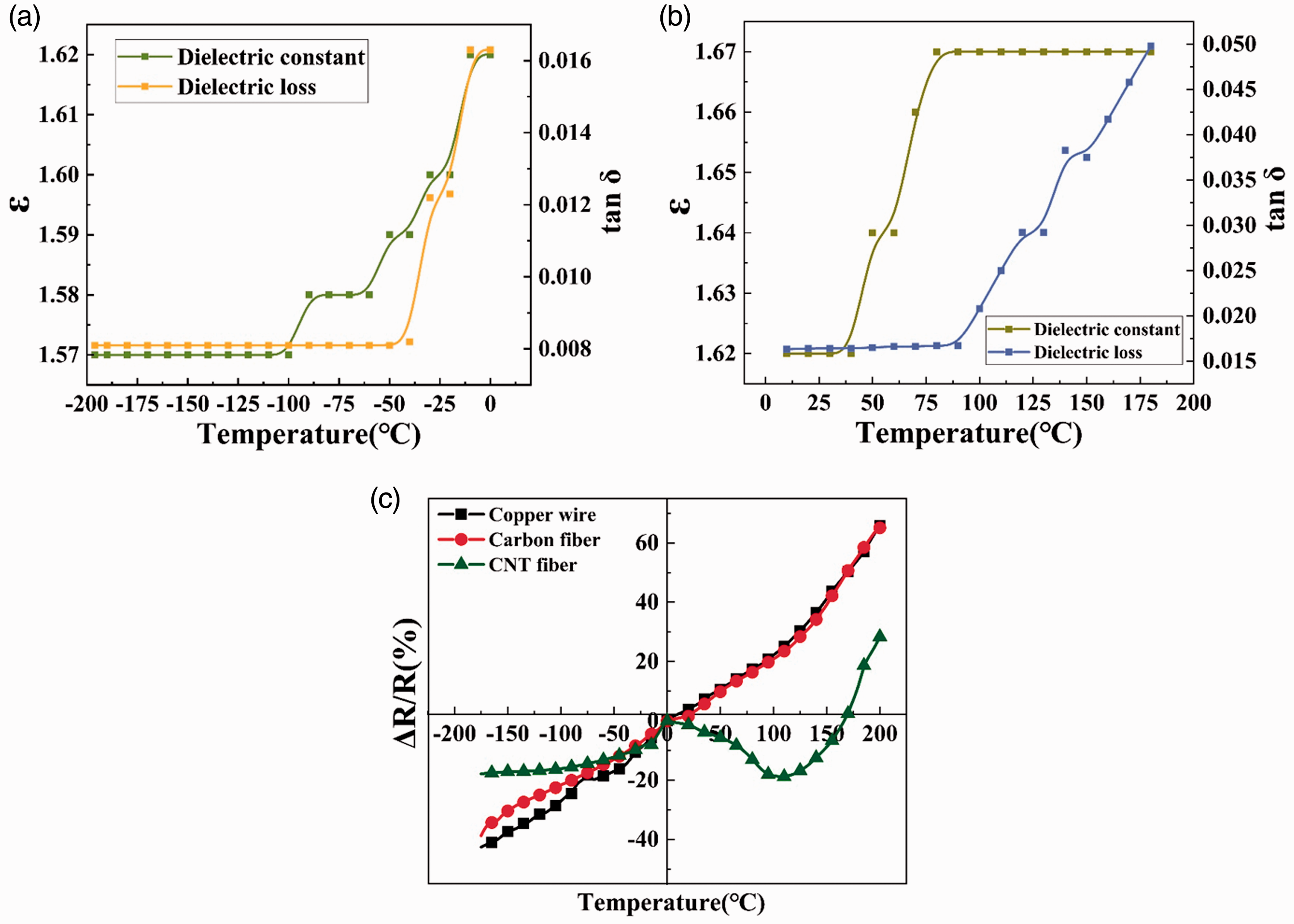
Dielectric constant and dielectric loss of 3DWSC in the temperatures from (a) –196°C to 0°C and (b) 20°C to 180°C; (c) variation of the resistance changes rate (ΔR/R) of the three conductive fibers with temperature.
According to the antenna design formula (supplementary Figure S4), the resonant frequency is determined by the dielectric constant
As shown in Figure 7(a), when the temperature increased from –196°C to –50°C, the dielectric loss of 3DWSC remained at 0.0081. When the temperature increased from –50°C to 0°C, it increased to 0.016, due to the intensification of dipole polarization of epoxy resulting from thermal motion of polar groups caused by the increase of temperature. 39 Similarly, when the temperature rises from 90°C to 180°C, as shown in Figure 7(b), the dielectric loss increased from 0.016 to 0.05, because of the polarization rotation of polar groups and small molecules triggered by the thermal expansion of the epoxy resin. The influence of humidity on the dielectric properties of 3DWSC was explored (Figure S6), and the results showed the dielectric properties of 3DWSC were not sensitive to humidity.
Figure 7(c) shows the change in resistance rate (ΔR/R) of the three types of conductive fibers with temperature. The change of resistance of copper wire and NCCF was similar, but the change of resistance of CNT fiber resemble that of a semiconductor. 40 When the temperature was low, as the temperature increased, the electrons in the CNT valence band were more likely to transition to the conduction band, and the conductivity increased. But at high temperatures, the electronic transition was hindered and the resistance increases. The change in the resistance of the conductive fibers resulted in the mismatch of the impedance between the radiating patch and feed line, which caused the S11 value of 3DWS-MA to increase with temperature changes in Figure 5(b–d) and Figure 6(b–d).
Therefore, the dielectric properties of 3DWSC and the conductivity of conductive fibers were changed by the increase of the temperature, which may affect the electromagnetic performance of 3DWS-MA. The 3DWS-MA (CNT yarn) exhibited the most stable S11 value at low temperatures (from –196°C to 0°C). The 3DWS-MA (copper) exhibited low return loss and stable resonance frequency at high temperatures (from 20°C to 150°C).
Conclusions
In this study, dielectric properties of 3DWSC, electrical properties of conductive fiber, and electromagnetic performance of 3DWS-MA were systematically investigated in various temperature conditions. The prepared antenna had good electromagnetic performance with S11 value of –23 dB and gain of 7 dB. With the temperature increase from –196°C to 150°C, the dielectric constant of 3DWSC increased from 1.57 to 1.67, resulting in the decrease of resonance frequency of 3DWS-MAs (maximum offset 60 MHz). The resistance changes rate of the conductive fiber reached 105%, resulting in a degradation in the S11 value (maximum 17 dB). At low temperatures (from –196°C to 0°C), the 3DWS-MA (CNT yarn) exhibited the most stable S11 value, while at high temperatures (from 20°C to 150°C), the 3DWS-MA (copper) exhibited low return loss and stable resonance frequency. This study is of great value to the practical applications of 3DWSC and 3DWS-MA in the fields of communication and aerospace.
Supplemental Material
sj-pdf-1-trj-10.1177_00405175211005015 - Supplemental material for Electromagnetic performance of three-dimensional woven spacer microstrip antenna with various conductive fibers in extreme temperatures
Supplemental material, sj-pdf-1-trj-10.1177_00405175211005015 for Electromagnetic performance of three-dimensional woven spacer microstrip antenna with various conductive fibers in extreme temperatures by Li Wuzhou, Zhang Kun, Zheng Liangang and Xu Fujun in Textile Research Journal
Footnotes
Declaration of conflicting interests
The author(s) declared no potential conflicts of interest with respect to the research, authorship and/or publication of this article.
Funding
The author(s) disclosed receipt of the following financial support for the research, authorship, and/or publication of this article: This work was financially supported by Natural Science Foundation of Shanghai (Grant No. 17ZR1400800).

Supplemental material
Supplemental material for this article is available online.
References
Supplementary Material
Please find the following supplemental material available below.
For Open Access articles published under a Creative Commons License, all supplemental material carries the same license as the article it is associated with.
For non-Open Access articles published, all supplemental material carries a non-exclusive license, and permission requests for re-use of supplemental material or any part of supplemental material shall be sent directly to the copyright owner as specified in the copyright notice associated with the article.
