



Abstract
This paper proposes a simulation method suitable for weft-knitted seamless kneepads. The purpose of this study is to realize the simulation of complete weft-knitted products, and it has the advantage of speed to display the simulation results online in real-time. The loop of the basic loop model is controlled by up to eight characteristic points and the yarn path is fitted by a three-dimensional spline curve. To string the loop model into the fabric, the coordinate of the characteristic point of the loop at other positions is obtained based on the loop model at the origin by using the translation matrix and the rotation matrix. The simulation of the weft-knitted kneepad is realized by the joint programming of Visual Studio and WebGL. The results show that the structure model can achieve the simulation of the kneepad with high efficiency. This method has strong real-time performance and practicability.
Weft-knitted seamless kneepad refers to fabric that is made by a seamless kneepad machine in one step. It has no seams and has a better fit than traditional knitted products. The seamless kneepad is of the sleeve wearable type; it is an integral structure. Different knitting stitches are used to fit the human knee structure. So, the simulation of this kind of product is used to highlight its three-dimensional (3D) tubular structure.
For the knitted fabric simulation, the current research is based on the spring particle model to solve the virtual display of fabric tiling, folding, collisions, and other problems, and to better simulate the dynamics of the fabric. The B-spline curve and Pierce loop model are used to simulate the loop structure from the microscopic point of view, which is helpful to identify the complex weaving process. The existing simulation technology has laid a good foundation for the research of loops, yarn, and fabric.
With the continuous improvement of computer technology and 3D simulation of the weft stitch structure becoming increasingly true, physical simulation of weft-knitted fabric has gradually become the focus of scholars' research. Among them, the mass–spring model and finite element analysis model are the most widely used. The comparison of different simulation implementation methods is shown in Figure 1. The basic idea of Provot 1 in using the mass–spring model to simulate knitted fabric is as follows: the fabric is a quadrilateral grid of particles connected by a spring, and the correspondence between the mass–spring model grid and the loop is established. On the fabric scale, the stress and deformation were simulated by the model, and then the coordinate of the control point of the loop was solved according to the mesh deformation. Based on the mass–spring model, not only is there a great deal of research, but many scholars have not only simulated the stress deformation of knitted fabric but also have simulated the phenomenon of stitch deformation caused by the change of stitch structure. Sha et al.2,3 proposed an improved cuboid model, and the interpolation algorithm can generate a new auxiliary point. They used the Velocity-Verlet numerical integration method to update the spatial displacement of particles and realized the 3D dynamic simulation of fancy weft-knitted fabric. Peng et al. 4 applied a simplified particle model to simulate fancy weft-knitted fabric, and the results show that it can accurately represent the deformation of the loop and the texture of the yarn.
The finite element analysis method is a numerical method to solve problems in engineering and mathematical physics. It is used to solve typical problems in the field of mathematics and related engineering. The finite element analysis model can easily simulate the structure of irregular objects, so it is applied in fabric simulation. Perumalsamy et al. 5 numerically simulated the tensile strain of double rib fabric in the transverse, longitudinal, and front and rear directions. Abghary et al. 6 used the piecewise function loop geometric model to simulate the spherical contact deformation of biaxial weft-knitted fabric. Oliver et al. 7 combined mesoscale simulation with the numerically homogenized yarn 3D beam model and the nonlinear orthotropic response surface model. Wadekar et al. 8 defines a single cost function to capture the various parameters of the loop geometry model. Wu et al. 9 built a virtual fiber model at the micro-scale to simulate the fiber interaction of knitted fabrics and the nonlinear characteristics of yarn under large deformation. Besides, Kaldor et al. 10 regard the yarn as an inextensible B-spline tube and, on this basis, take the bending and friction of the yarn into consideration for simulation, and achieve a good simulation effect. Cirio et al. 11 increased the processing speed by an order of magnitude by treating yarn-to-yarn contact as persistent.
Many scholars have conducted studies to improve the yarn's sense of reality. Xu et al. 13 inserted Lumislic slices with random brightness changes in the middle of the type value points. This slice is composed of random points and rotates the slices according to the twist angle to obtain twist strands with a strong sense of reality. Zhao et al. 14 combined regular fibers with fibers floating on the surface to build a high-quality yarn model with fiber-level details. Jiang et al. 15 performed texture mapping, texture interpolation, and brightness processing on the model to simulate a clear and realistic deformation loop. For the simulation of tubular knitted fabrics, Wu et al. 16 and Yuksel et al. 17 incorporated displacement path operation into their knitted mesh model to enable the yarns to be helically woven in horizontal rows. Kaspar et al. 18 also described the seamless structure of knitted fabric in the computer simulation of flat machine products.
Based on previous researches on the 3D simulation of weft-knitted fabrics by scholars, this paper proposes a simulation method suitable for weft-knitted seamless kneepads, the physical fabric is shown in Figure 2. The purpose of this study is to realize the simulation of complete weft-knitted products, and it has the advantage of speed to display the simulation results online in real-time.
Modeling the three-dimensional structure of the weft-knitted fabric
Weft-knitted fabric is formed by overlapping yarn. In this paper, the yarn loop is used as the basic unit to simulate the fabric. Modeling a weft-knitted fabric includes defining the type of loop, the configuration of the loop, the path of the loop, and the deformation of the loop.


Weft-knitted seamless kneepad.

ZY550HS automatic jacquard kneepad machine.
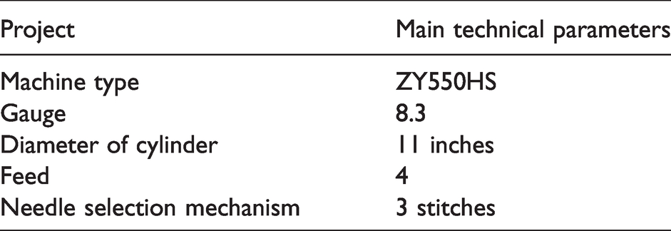
According to the rule of loops in a weft-knitted fabric many types of loops can be formed, such as knit, tuck, float, and weft repetition. By observing the weft-knitting structure, it is found that the type of the loop can be changed based on the knit structure. As shown in Figure 4(a), on the premise that the loop shape can be maintained, we take eight points as the characteristic points of the knit loop structure based on related research on the knitting loop model.3,19 The real fabric was knitted by a ZY550HS automatic jacquard kneepad machine, as shown in Figure 3 and Table 1 (Zuoyou Knitting Goods Co., Ltd, China, Wuxi). The ZY550HS machine specializes in the production of sports, medical, health knitted kneepads, elbow pads, and other equipment, with seamless, jacquard functions. This machine is fully capable of producing a weft-knitted seamless kneepad and meets the experimental requirements. The apparatus used to observe the fabric is z XTZ-D continuous ploidy visual microscope (Shanghai CSOIF Co., Ltd, China, Shanghai).
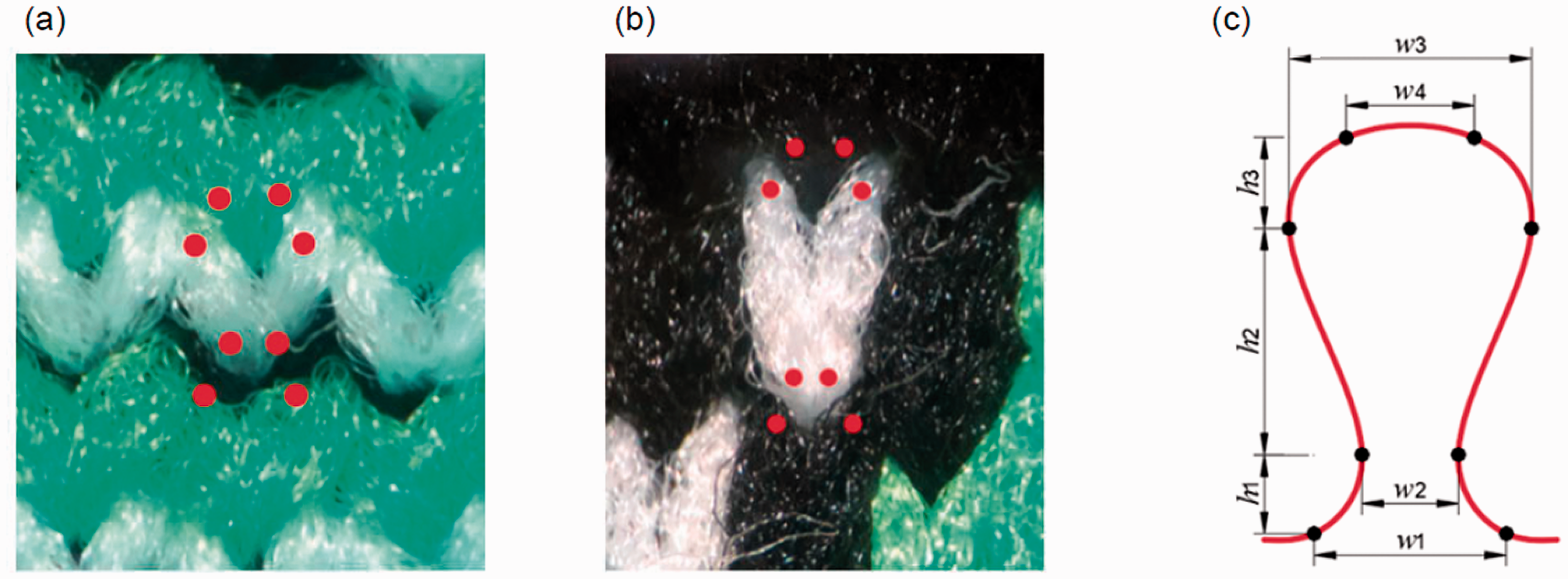
Physical drawing of the knit loop structure: (a) back loops; (b) face loops; (c) ideal loop structure model.
Figure 5 shows the yarn loop model of the front loop and the reverse loop, where P0–P15 are at the starting and ending points of the rib loop, as shown in Figure 5(a). The parameters of the rib loop model are as follows: loop width W, loop height H, and thickness L of the fabric. The geometric model of the tuck, float, and transfer is obtained by adjusting the rib loop model, as shown in Figure 6. Because the knit structure defines eight points (P0–P7), the tuck structure only takes six points (P0, P2–P5, P7) and, similarly, the float structure only takes two points (P0, P7).
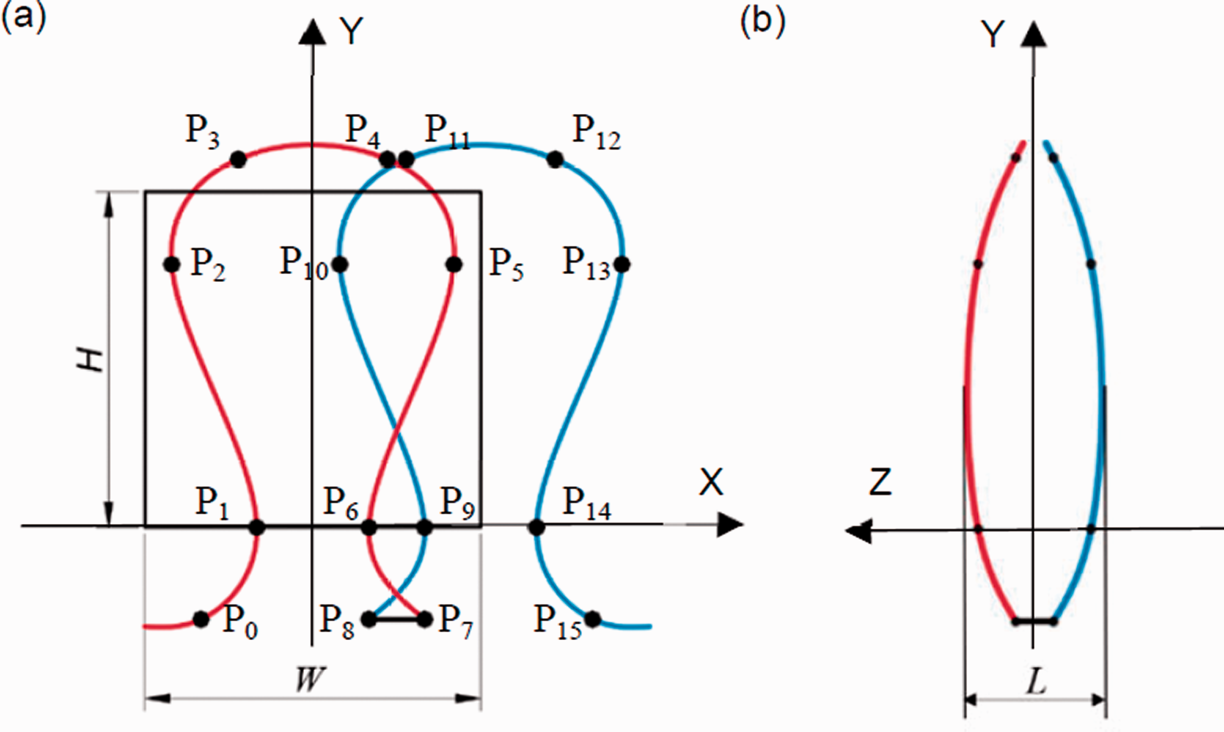
Rib loop model: (a) front view of the characteristic points of the rib loop model; (b) lateral view of the characteristic points of the rib loop model.
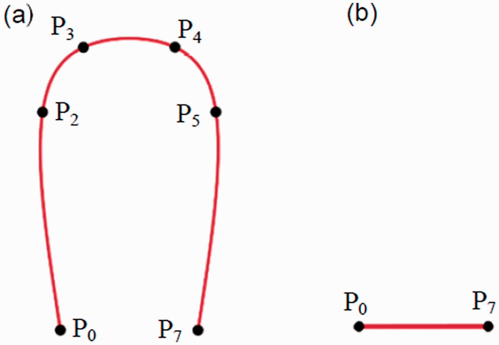
Geometric models of different loops: (a) tuck; (b) float.
Here, P0–P15 are characteristic points of the rib loop model, and their position determines the loop's shape. The specific method of determining the coordinate of the characteristic points will be described in the following paragraphs. The centerline of the yarn passes through the characteristic points, and the path of the yarn is represented by a 3D spline curve. Spline curves are completely piecewise polynomials composed of any number of curve segments, so changing one characteristic point does not affect the shape of other curve segments. 20
The loop path is represented by a 3D spline curve passing through the center of the yarn. A spline curve is a kind of parametric curve with uniform expression, accurate simulation, and flexible control. The form of the spline curve is suitable for yarn shape control in complex fabrics. Further, to simplify the representation for computation and rendering later, we assume a piecewise linear property of the yarn and use a series of straight tube segments for approximation.
CatmullRomCurve3 in Three.js is used to form a 3D spline curve that provides multiple attribute parameters to draw a smooth loop. CatmullRomCurve3 controls the shape of the curve through the parameter of characteristic points. To further confirm the values of h1, h2, h3, w1, w2, w3, w4 in the knit loop model, different parts of the kneepad fabric, as shown in Figure 4, are selected for measurement.
The micrographs of these fabrics were measured to obtain the 3D structure of the yarns inside the fabrics. During the measurement process, 10 loops of different positions were selected for measurement and their average values were taken. The specific test results are shown in Table 2.
Main technical parameters of the ZY550HS automatic jacquard kneepad machine
Distance between each characteristic point and centerline in the ideal loop

As can be seen from Table 2, there is little difference between the width dimensions of the back and face loops. The height of the needle loops varies. Because the sample is tricolor jacquard, the face and back course ratio is 1:3, and the difference between the h2 of the back loop and the h2 of the front loop is denoted as Δh, and Δh multiplied by 1.5 is the face loop height H. The w3 plus yarn diameter 2*r is the face loop width W. The z-coordinates in the direction of thickness refer to previous research; the specific coordinates of each characteristic point in the knit loop are shown in Table 3.
The proportional relationship between characteristic points and the loop structure parameters

Because the double-jersey jacquard kneepad is selectively jacquard knitted on the front side of the fabric, the phenomenon that the front side loop is higher than the backside loop will longer will appear. The deformation of the loop that we talked about before is the problem of the face loop caused by the different heights of the face and back loops of the kneepad, as shown in Figure 4. So, we need to correct the coordinates of the needle loop of the front loop, that is, change the y-coordinate of P2–P5 according to the interloop relationship.
In one wale of fabric, if loop B is not knitted, the needle loop of loop A shall be raised to the position of loop B, as shown in Figure 7. This causes loop A’s height to increase. The number of consecutive unknitted loops in the same wale is defined as c, then the y-coordinate of the characteristic point on the needle loop is related to c, as shown in Equation (1)


Diagram of the loop unknitted.
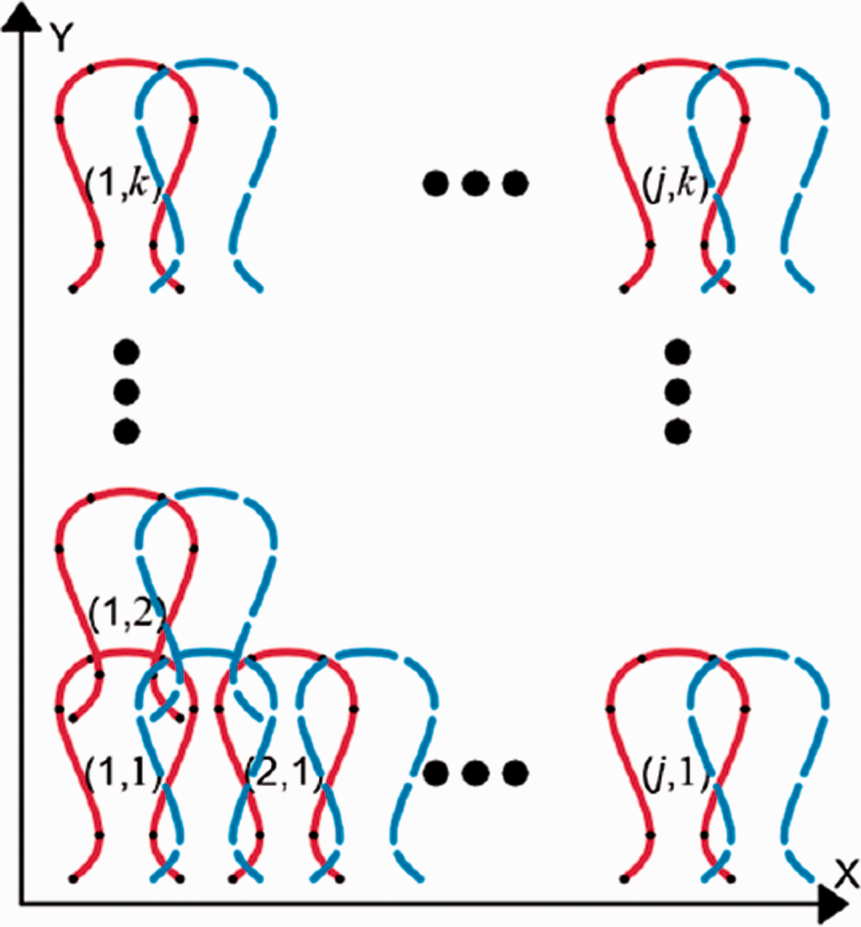
Loop translation diagram.

(a) Tubular kneepad. (b) Loop rotation diagram.

The results of different values of two parameters of TubeBufferGeometry: (a) tubular segments; (b) radial segments.
In the computer jacquard knitting machine, the knitting diagram is usually used to describe the knitting condition of the knitting needles. According to each knitting information, the needle is selected to form a loop, tuck, or float. To identify the information of needle selection conveniently and accurately in the computer, we use a two-dimensional (2D) matrix 

Modeling the three-dimensional structure of weft-knitted kneepads
Translation matrix operation
Weft-knitted fabric is formed of several yarns from the barrel along the weft direction of the sequence of the pad on the knitting needle to form a loop, and in the longitudinal interlaced formation. Therefore, the loops, as the smallest unit of the knitted fabric, are arranged in a certain number both vertically and horizontally. The double-jersey complete jacquard stitch refers to a double-jersey jacquard stitch in which all dial needles are knit when the reverse loops are knitting in each feeder.
Taking the cylinder needle knitting and dial needle knitting as an example, as shown in Figure 8, we take the lower-left corner of the coordinate system as the origin and shift the characteristic points of the loop model to the position of the kth row and the jth wale, that is, the x-coordinate of each type value point plus (j–1)*W, the y-coordinate plus w, and the z-coordinate remain unchanged; the matrix operation is shown in Equation (4)

Rotation operation
To make the simulation of the kneepad more 3D, we changed the translation operation of the loop graph element into rotation, as shown in Figure 9. To make the calculation easier, we set the y-axis as the central axis, so adding R to the z-coordinate of the characteristic points of the basic loop.
We write the width of the kneepad as ww and the height as hh, ww circular loops are arranged, with the perimeter as ww*W, so the radius R is 



According to the above coordinate rotation algorithm, the resulting kneepad will have the appearance of a cylinder. To obtain a simulation result that conforms to the shape of the human leg, we add a variable Δz to the formula of the z-coordinate, as shown in Equation (8)

We construct a sine function with row number k as the independent variable and the variable Δz as the dependent variable. The height hh of the kneepad pattern is set as half of the minimum cycle interval of the sine function, and the maximum is set as 1.5 times the kneepad radius R.
TubeBufferGeometry
BufferGeometry is an efficient representation of mesh, line, or point geometry. It includes vertex positions, face indices, normals, colors, ultraviolet (UV) light, and custom attributes within buffers, reducing the cost of passing all this data to the graphics processing unit (GPU). The secret of its efficiency is to put the data in contiguous memory space, as contiguous storage space can save the time of passing the data to the central processing unit (CPU).
When parsing a Geometry object, if the Geometry object is Geometry, the Three-js WebGL renderer will convert the Geometry to BufferGeometry and then extract the vertex information contained in the BufferGeometry. We can see from this process that using BufferGeometry directly eliminates the need to use Geometry in the middle. This improves the efficiency of the renderer.
In this paper, the 3D unit loop model incorporating TubeBufferGeometry and Three.js in spline curves is proposed for geometrically modeling 3D weft-knitted structures. The TubeBufferGeometry Constructor has several parameters, of which two parameters are closely related to the quality and performance of constructing TubeBufferGeometry, namely, tubular segments and radial segments. Tubular segments represent the number of segments that make up the tube, and radial segments represent the number of segments in the cross-section of the tube, the tube effects under different parameters are shown in Figure 10.
Results and discussion
To achieve a real-time realistic simulation effect on the premise of reducing the threshold of computer configuration, the experimental computer is equipped with an Intel Core i5-1035G1 central processor (specification: 3.60 GHz, 8 GB RAM) and an NVIDIA GeForce MX250 graphics card.
Our knitted fabric computer-aided design (CAD) system is based on browser development; users can directly access it through a computer or mobile intelligent terminal anytime and anywhere through the Web browser design of the knitted fabric. WebGL is a JavaScript API (application programming interface) that renders high-performance interactive 3D and 2D graphics in any compatible Web browser without the need for plug-ins. So, to simulate the fabric in a browser, we chose the joint programming of Visual Studio and WebGL.
Simulation of the kneepad
Figure 12 shows the plane expansion of the kneepad simulated by the translation matrix algorithm. Figure 13 shows the 3D display of the kneepad simulated by the rotation matrix algorithm.
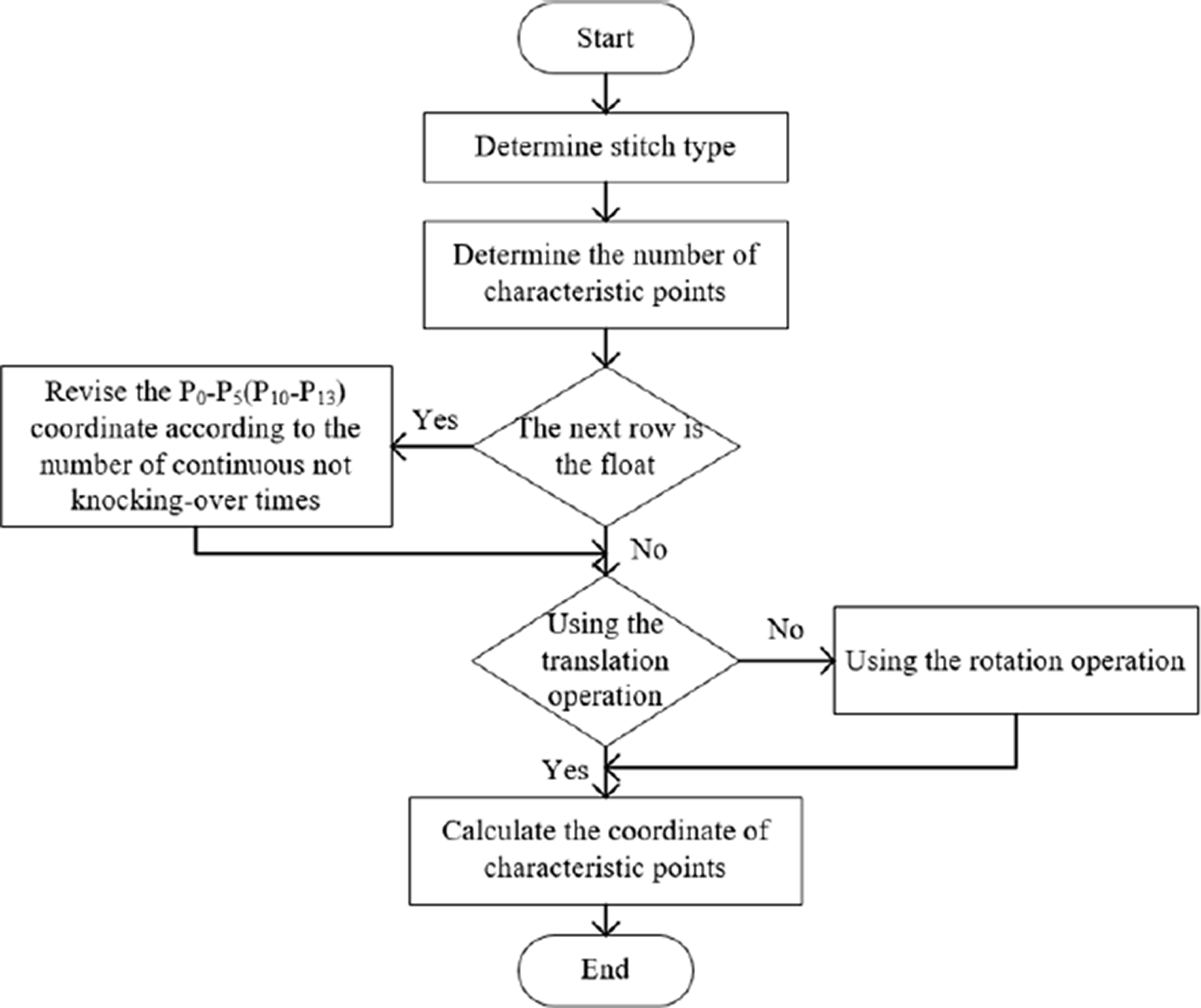
Workflow of the kneepad simulation.

Simulation of kneepad: (a) design pattern of the kneepad; (b) kneepad plane simulation diagram (24*ww tubular segments, six radial segments); (c) jacquard part kneepad plane simulation.
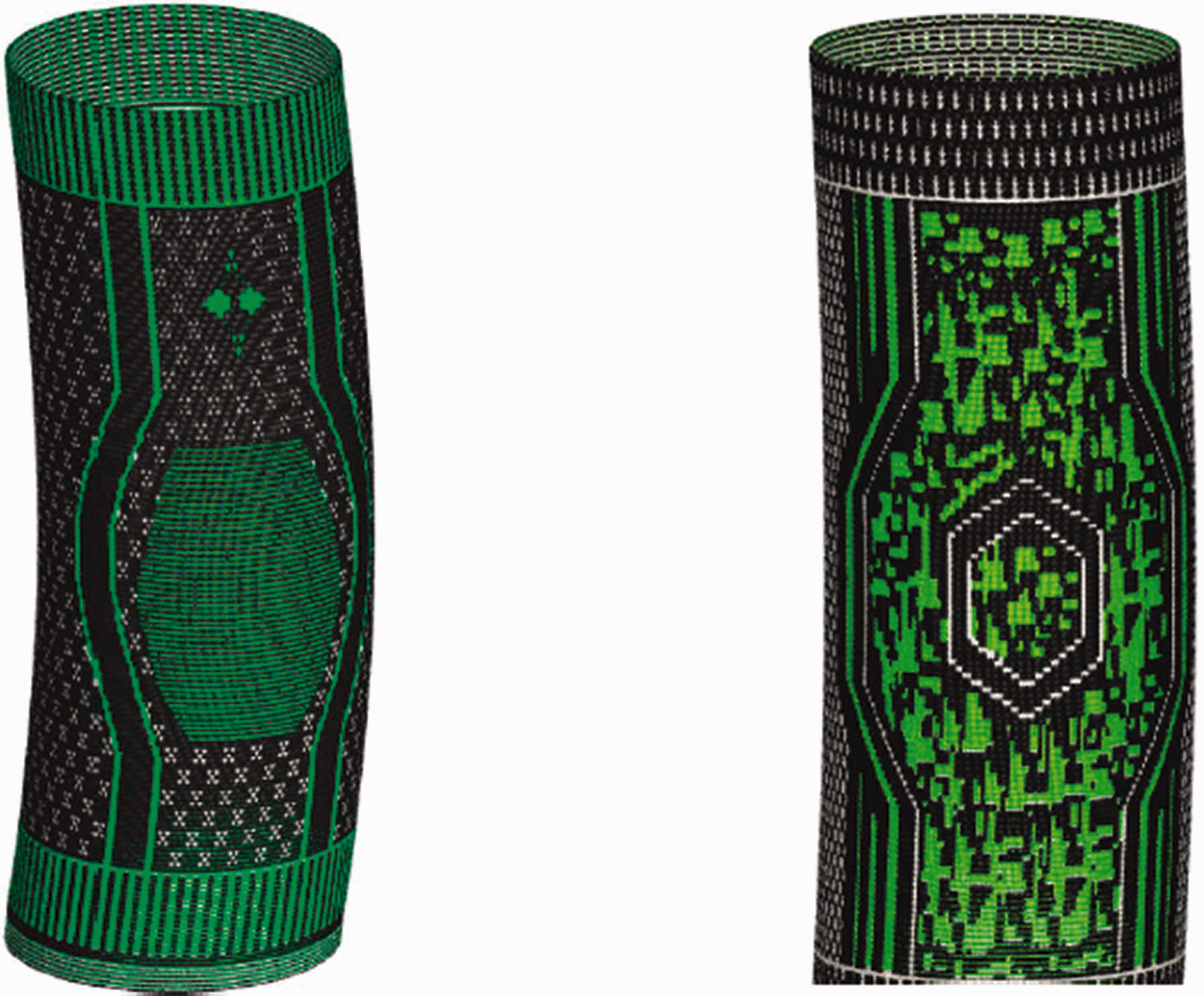
Virtual display of the kneepad (24*ww tubular segments, 12 radial segments).
Analysis of simulation efficiency
We set a different number of tube segments and tube surfaces to obtain a simulation of different effects. The simulation results of two loop arrangement models are shown in Table 4.
Runtime performance of the simulation

It can be found from the table that the simulation time will lengthen when the number of segments and the number of segments in the cross-section increase. The larger these two parameters are, the smoother the tube will be, but the corresponding rendering speed will decrease. The rotation operation is more computationally intensive, so the simulation takes longer.
Conclusions
In this paper, we proposed two loop coordinate matrix operations to achieve different simulation results of a complete weft-knitted seamless kneepad. Besides, the influence of yarn model parameters on the simulation results and simulation time is also analyzed. The results show that using TubeBufferGeometry can greatly improve the rendering efficiency and realize the online simulation of tens of thousands of loops. The finer the yarn surface subdivision is, the higher the fabric image definition is, and the better the simulation effect is. The finer the yarn surface subdivision, the longer the simulation time. Our analysis shows that the parameters can be selected based on the size of the fabric and the desired display effect. On the premise of good appearance simulation, the proposed method has the advantage of speed to display the simulation results online in real-time.
Footnotes
Declaration of conflicting interests
The authors declared no potential conflicts of interest with respect to the research, authorship, and/or publication of this article.
Funding
The authors disclosed receipt of the following financial support for the research, authorship, and/or publication of this article: This work was supported by the National Science Foundation of China (Grant No. 61772238) and Taishan Industry Leading Talents (Grant No. tscy20180224).
