



Abstract
In recent decades, attention has been focused on the design of protective soft fabrics against cutting. The anticipated textiles should shield the wearer's body from threats caused by pointed or sharp-edged objects, such as a knife, sharp blade, or spike. Therefore, as it is of great importance to design slash-resistant fabrics, it is also necessary to have an apparatus that gives the possibility to simulate the conditions of cutting processes of the protective fabric. The main objective of the present work is to develop a new apparatus to test the slash-proof materials used in soft protective armor or gloves. The apparatus can test the material with different cutting angles, different speeds, and various normal forces applied to the sample at the point of contact between the material and the cutting blade, with the capability to change all the parameters affecting the cutting force. This study aims to develop a cutting apparatus to study the cutting mechanism of textile materials with the capability to change all the parameters affecting the cutting force. The cutting angle and cutting speed have a significant effect on the maximum cutting force; however, the latter showed a high decrease of the maximum cutting force.
In many industrial applications, cutting processes are applied, and therefore personal protective equipment is necessary for workers’ protection from being injured by cutting tools such as a knife, saw, or other sharp objects. This brings the necessity to protect against the danger of trauma by knives and other sharp instruments.1,2 There are several methods to evaluate the cutting resistance of material that are standardized by several international organizations, such as the European standard EN388 2016, the American Society for Testing Material ASTM- F1790-97, and the International Standardization Organization (ISO-13997). The principles of testing methods for material cutting resistance can be summarized as follows.2,3
Static blade test – weights can be changed to modify the force applied to the blade, as well as the blade itself, as it cuts through a test piece mounted on a curved surface.
Linear movable blade test – applying a certain force onto a sharp blade that travels over a test sample. The sample is laid on a curved grooved mandrel. The value that determines the cut level is defined as that required for the blade to cut through the material after traveling 20 mm.
Reciprocating rotating circular blade – rotating circular blade moving back and forth on the surface of the sample under a vertical force of 5 N. The number of revolutions of the blade to cause a cut-through of the specimen will be used to calculate the cut index. The cut resistance of the tested fabric is compared to the resistance of a reference cotton fabric, and the ratio between the two is known as the “Cut Index.”
Drop-mass tests – the stab energy is measured when a penetrator (which consists of dropped 2 kg mass and knife or spike) enters the fabric. The kinetic energy of the cutting is determined by the mass of the penetrator and the fall height, 0.5–3 m.
The difference between the above methods mainly is in the method of the application of the load, the sample mobility, and the nature of the load application (static or dynamic). It can be used in the comparison of the cutting resistance behavior, either between the cut samples or related to the standard sample. The material cut resistance under a specified load is related to a cutting action by a smooth sharp edge across the surface of the material. 1 According to ASTM F1790-97 and ASTMF1790-05, the cut protection performance tester (CPPT) is widely used for the classification of cut resistance level, where the weight in grams can be applied to a razor blade while moving the blade over the fabric without cutting through the fabric more than 20 mm. The ranking of cut protection performance (CPP) has nine levels: for the cut-through the distance is 25.4 mm. For EN 388 standards, the CPP level for cut resistance is measured using a circular, free rotating blade under the pressure of a standard weight 5 [N], which moves backward and forward over the surface of the tested material over a fixed stroke length.
During the real situation of the fabric in the case of cutting, the yarns in the fabric are subjected to complex stresses such as tension, flexure, and shear, which are not static but dynamic. In the situation when the yarn or fabric might deform under the cutting force, the fabric will fail under shear stress and tensile stress.
Consequently, the evaluation of the cut resistance, punching resistance, stab, or slash will differ according to the type of the testing system used, which can be summarized as follows.
NIJ 0115.008. Judging criteria: value for stab resistance energy, strike energies. The armor shall not allow penetration of a knife blade or spike more than 7 mm.4 HOSDB Body Armour Standards for UK Police (2007) Part 3. Judging criteria: pass or fail test. No penetration of the spike is permitted.5 ASTM F1790/F1790M3. Judging criteria: value cut resistance level; the weight needed (in g) to cut through the material with a 20 mm blade.6 EN 388, 2003. Judging criteria: the performance rating scale (Cut Index); the ratio of the number of cycles to cut the sample compared to the resistance of a reference cotton fabric.7 ASTM D3763. Judging criteria: the energy at maximum force and total energy to break using load–deflection curves.8 ISO 13997. Judging criteria: the depth of blade travel is used for pass/fail criterion; several cuts (five cuts in the range of 5–15 mm).9 ASTM F1342. Judging criteria: the measured force is used for pass/fail criteria. If the load is 20–60 [N], the material is considered low puncture resistance, 60–100 [N], moderate, and >100 N for high puncture resistance.10 HOSDB 008/18. This addresses materials designed to protect against aggressive short-duration swipes of an edged weapon across the body to ensure that the slash-resistant materials satisfy the particular requirements. The guided drop assembly with the test blade will freely fall to hit the mounted for test samples. The minimum perforation force is 30–60 [N].11
The test procedures of some standards are similar, such as in the case of ISO 13997 and ASTM F 1790, but different in the length of cut of the fabric by the edge of the blade. The assessment of the protective fabric emphasized the testing apparatus used and method of evaluation. ISO 13997, ASTM F1790, and ASTM F2992TDM recommends the use of a TDM-100 cut test machine to determine the cut resistance of protective gloves by the TDM method according to ISO 13997. The tester is designed to determine resistance to cutting by sharp edges, such as knives, sheet metal parts, swarf, glass, and bladed tools.11,12
Cutting testing equipment has various designs, each recommended by specific standard associations such as the CPPT, the device used in ASTM F1790, the mCPPT – modified cut protection performance tester, a modified version of the CPPT, used for testing materials with high friction in ASTM F1790, TDM-100 – tomodynamometer, the device used in ISO 13997 and ASTM F1790-05, and the COUPTEST device used in EN 388. Several researchers have worked on introduced testers for the determination of the cutting resistance of fibers, yarns, and fabrics, which in each case can be applied for performing cutting of the material according to its end-use.13–22 The emphasis has been placed on the recent developments in both test standards and experimental methodologies used to evaluate stab and slash protection.1–3 The chain saw cut resistance tester is an apparatus that can be used for testing the protective fabrics required for hand-held chain saw users, according to EN 381-1.
The analysis of the literature established that there still is the need to design a tester that can replicate the actual condition when the fabric is subjected to a real cutting and allow one to change all the parameters of that process: the value of the normal load, the value of pre-tension, the speed of the cutting blade, the blade cutting angle, blade sharpness, and blade orientation. Hence, the existing tester is not designed to predict the “real” in-use performance of the considered protective fabrics.
Material and methods
Material
A commercial cotton plain weave fabric of the following specifications: 22 warp/cm, 18 weft/cm, weft count 50 tex, warp count 43 tex, fabric GSM 220 g/m2, fabric breaking load 5.82 [N], and fabric break strain 0.4 was chosen to test the reliability of the setup in determining the cutting resistance.
Design of the setup
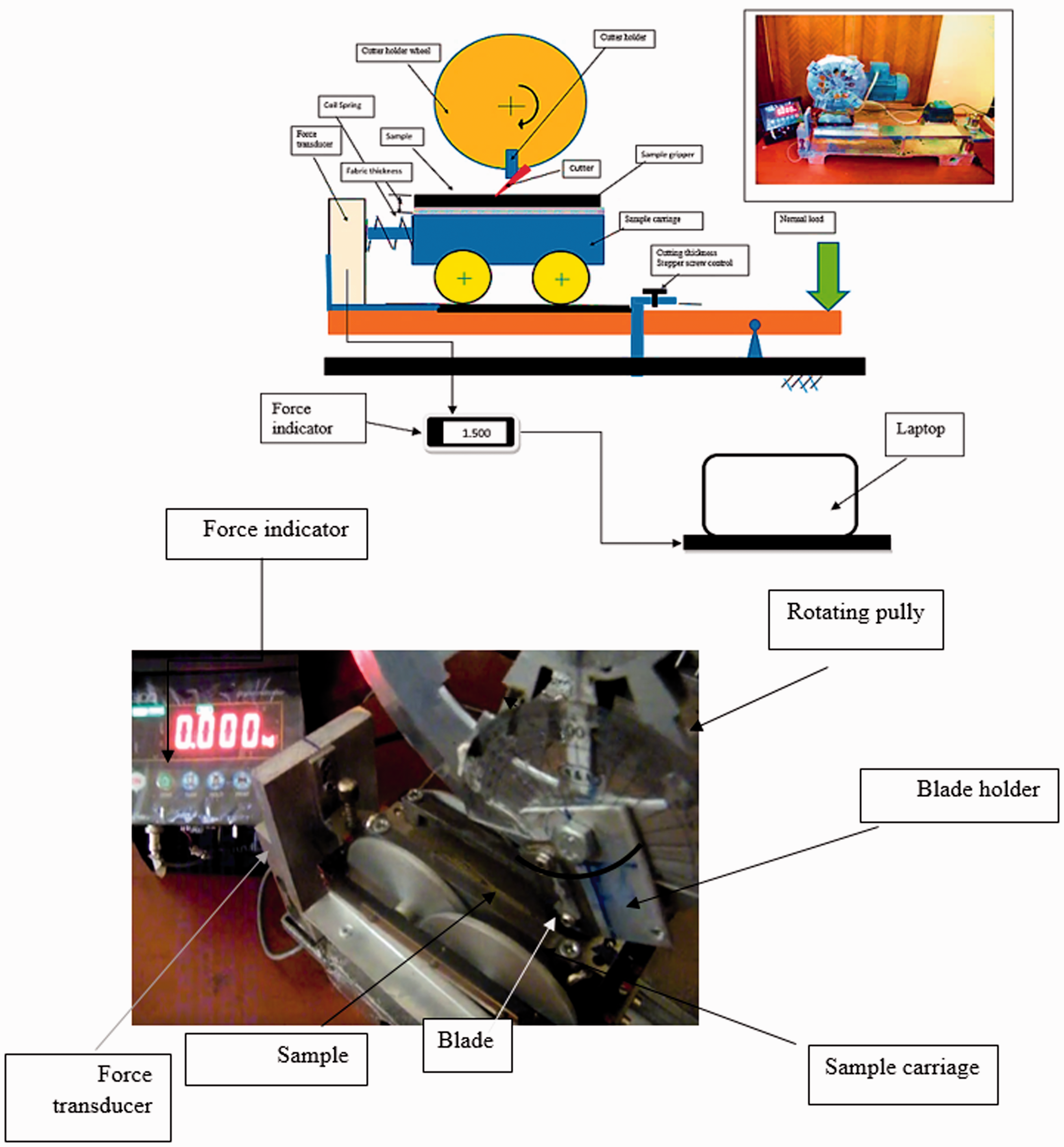
A prototype of the test apparatus was developed to satisfy the requirements for measuring the cutting of the fabric as well as the cutting resistance of the fibers and yarns. Figure 1 illustrates the main elements of the setup.
Sketch of the designed cutting setup.
Test procedure
Figure 1 shows the fixture for gripping a fiber, yarn, or fabric sample on opposing sides. To mount a fabric sample for cut testing, one end of fabric was clamped in the test fixture, and then the fabric was pre-tensioned to 5 cN using a static weight. While under tension, the second fabric sample end was clamped. To execute a cut experiment, a fabric sample was fixed in the sample carriage that was provided with a frictionless bearing moving on the loading lever. The movement of the carriage presses a force cell that measures the cutting force during the movement of the carriage due to the cutting of the sample by the blade. The rpm of the blade holder was adjusted through a variable speed motor with the ability to adjust the test speed from 0 to 1500 mm/s. When the test started, the blade was lowered until the fabric was contacted, loaded, and then completely cut off. Cutting force versus displacement curves was measured. Five repetitions were conducted for each blade angle ζ, normal load [N], and cutting velocity. Marks were placed on the fabric near the grip and were visually inspected after testing to ensure that the fabric did not slip in the grips during the cutting test. A new blade cutting edge was used for each experiment to minimize the blade dulling effect. The results were recorded on a laptop using a special program (Serial Port Monitor from Eltima Software®), and the rate of collection of the date was adjusted to be at least 10 readings per record along the yarn cut width. The values of the cutting force (CF) were recorded and analyzed. The average maximum cutting force (CFmax) [N] and cutting energy (CE) [J] was calculated for each sample.
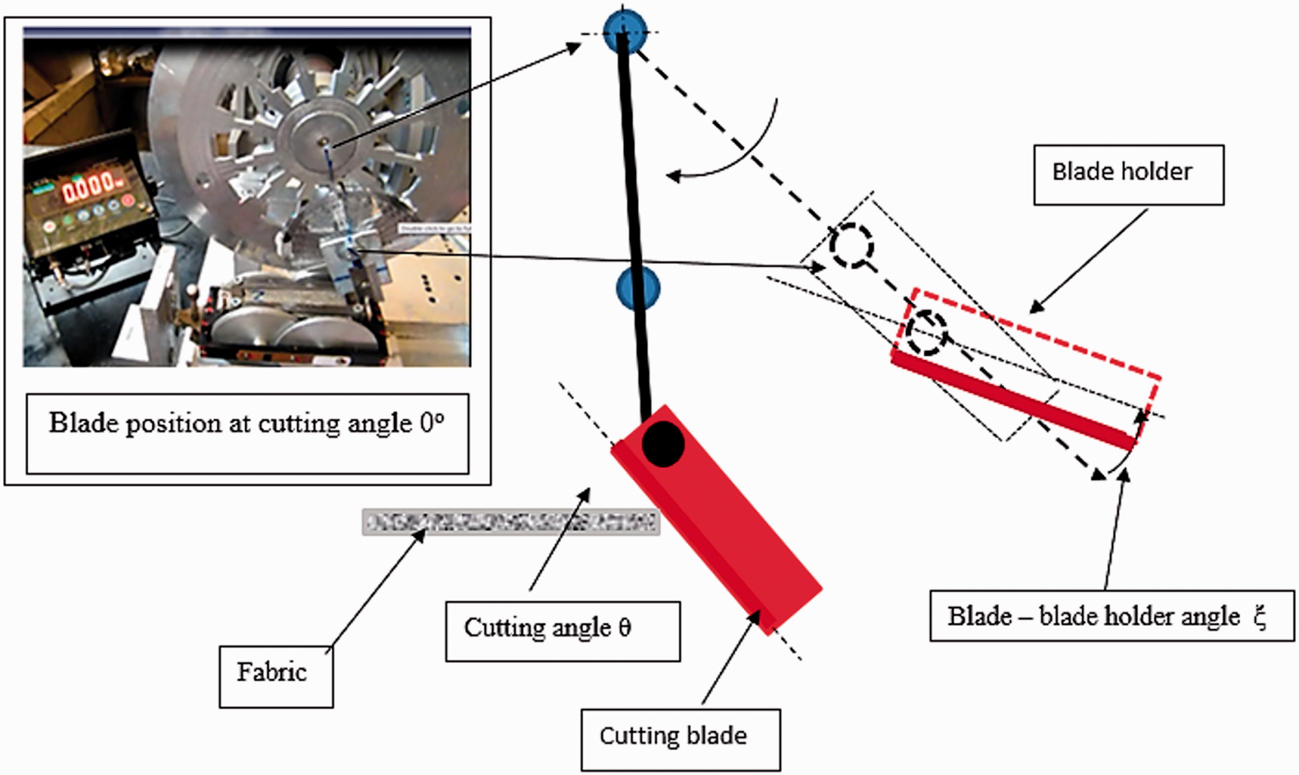
The cutting angle can be adjusted to satisfy the condition of cutting application with different attacking angles, as illustrated in Figure 2. The inclination of the blade edge to the blade holder with angle θ will change the maximum cut length. In the meantime, the blade can be adjusted so that the tip of the blade initially penetrates the fabric, and the edge of the blade starts the fabric cutting.
Blade inclination.
Results and discussion
Design parameters of the cutting setup
In this design, the cutting blade is fixed in the cutting blade holder with the possibility to change the angle of inclination θ of the blade edge to the blade holder. Figure 3(a) shows the trajectory of the cutting blade edge during rotation of the blade holder. The blade holder can rotate to change the angle of attack of the blade to the fabric surface, as shown in Figure 3(b)


Movement of the cutting blade through the sample.
The calculated maximum cut length, Figure 4, Lmaxcut, should be greater than the sample’s width; in the setup design the cut length is 100 mm. The angle of rotation of the sample holder can be changed to imitate the movement of the blade during the cutting


The maximum cut length calculations.
The rotation of the blade by cutting angle θ position II, Figure 5, affects the maximum cut length and will be shorter as the cutting angle θ increases.

Analysis of the sample cutting geometry. Fabric thickness (tm); fabric cutting angle (θ).
The force applied during blade travel through the material cutting at the point of contact is constant. 22 The material at the point of contact with the blade will move along the blade edge as the blade moves through.
Analysis of the mechanism of cutting in the setup
The cutting capacity of the blade depends on the blade sharpness, coefficient of friction, fiber materials and cutting blade material, the value of normal force on the sample, and the cutting angle. The cutting force of the material depends on the mechanical properties of the cut sample, the tensile property, the Young’s modulus, and its shear stress as well as the cutting angle.
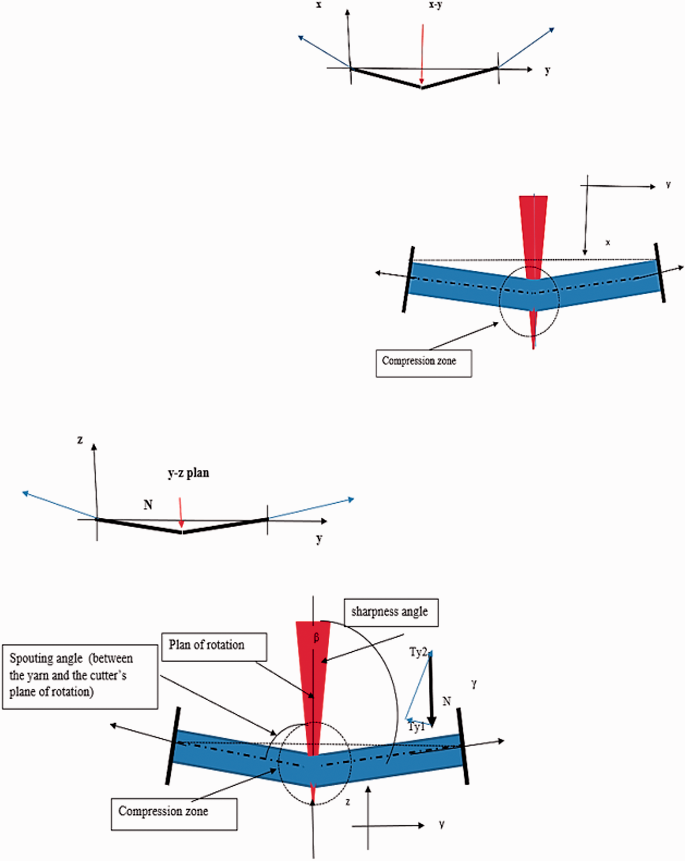
The analysis videos of the cutting process of the yarns or fabric on the setup, illustrated in Figure 6, indicates that the material was deformed during cutting in both the X–Y and Y–Z planes, and the contact point of the material slides over the blade edge.
Mechanism of cutting, fabric cutting angle θ.
According to the analysis of different samples, Figure 7 indicates the deformation of the yarn or the fabrics when the cutting blade comes into contact with it. The blade will press the yarn or fabric down and forward as shown in the photos, creating a tensile stress in the X–Y and Y–Z planes.

Cutting process of yarn and fabric.
Equilibrium equation of forces
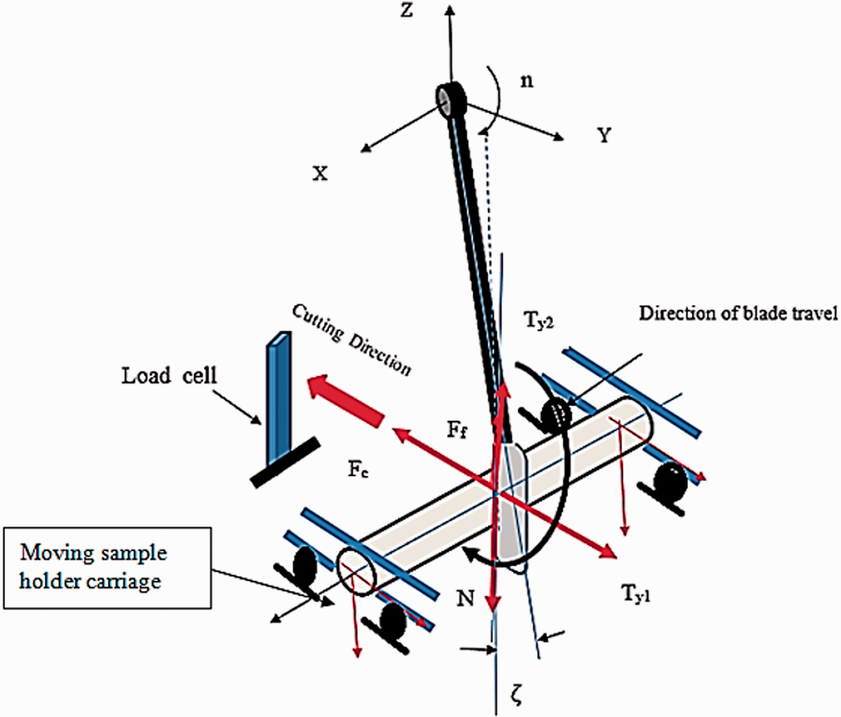
A mathematical model was developed to simulate the blade's movement and analyze its resulting linearity. This model calculates the expected cutting force Fc under different cutting conditions: materials with different coefficients of friction, normal load, cutting velocity, cutting angle, yarn, or fabric mechanical properties. Figure 8 illustrates the mechanism of cutting.
Deformation of the sample during cutting.
During the cutting process, the forces at the start will build up and continue until all the yarns are completely cut out. The analysis of the forces acting on the yarn during cutting on the Y and Z axes is shown in Figure 9, assuming the forces lie in one plane, Y–Z, only.

Forces acting on the yarn during cutting.
Analysis of the forces in I-I and II-II directions
The following set of equilibrium equations calculates the normal force (Fc)


The cutting force value due to the movement of the blade through the yarn is

Due to the deformation of the yarn in the X–Y plane, the yarn tension Ty2 will be tilted to the Z-axis by a small angle λ. The tensions can be approximated to

where Ty1 is the resultant tension due to straining of the yarn in the X–Y plane, Ty2 is the resultant tension due to the straining of the yarn in the Y–Z plane, N is normal force acting on the yarn during cutting, and Fc is cutting force. Ff is the friction force between the blade and the sample

where μ is the coefficient of friction between the yarn and the blade and λ is the angle of inclination of the force Ty2 to the normal load N during the cutting. The value of angle λ depends on the physical properties of the yarn. The value of the cutting force will be a function of the normal force N, μ, and angle of inclination of the blade θ, as well as λ. Yarn will be cut if its cutting value is less than that calculated by Equation (3); if it is more, then the uncut yarn will be dragged by the blade. Therefore, a higher value of normal force is required until the cut occurs. Figure 10 illustrates the effect of normal load on the expected cutting force; the increased angle of inclination of the blade θ reduces the value of Fc.
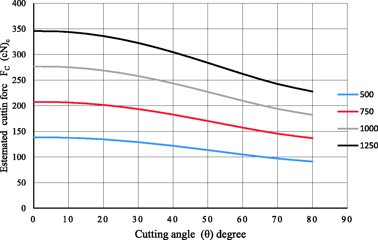
Estimated cutting force versus blade angle of inclination for the different normal loads, λ = 10 degrees.
The calculations by Equation (5) for constant normal force (N) indicate that as the angle λ increased the value of Fc increases, as shown in Figure 11.
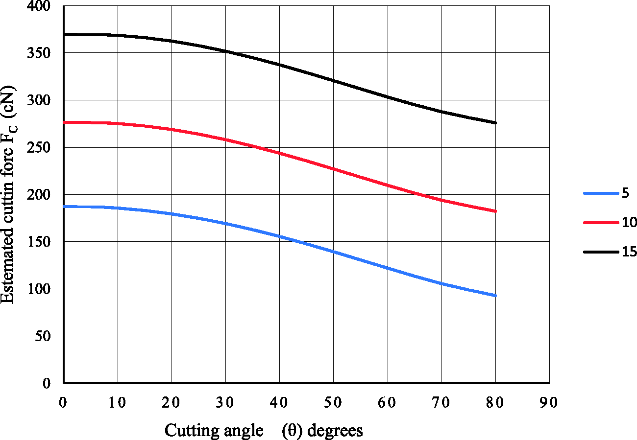
Estimated cutting force versus blade angle of inclination for different λ at normal load (N = 1000 g).
Fabric cutting force
The mechanism of cutting of the fabric in the setup consists of tensile stress, bending stress, and shear stress, which simulate the cutting of the material when subjected to cutting forces in many applications. This is due to the failure initiation site on the tensile failure, flexure, or shear failure. According to the Maximum Principal Stress theory, the Equivalent Stress is

σ z = Ty2/(cross-section area of the yarn)
σ y = Ty1/(cross-section area of the yarn)
τ xy = yarn shear stress
Typical failure patterns of the fabric at different cutting angles θ are shown in Figure 12.
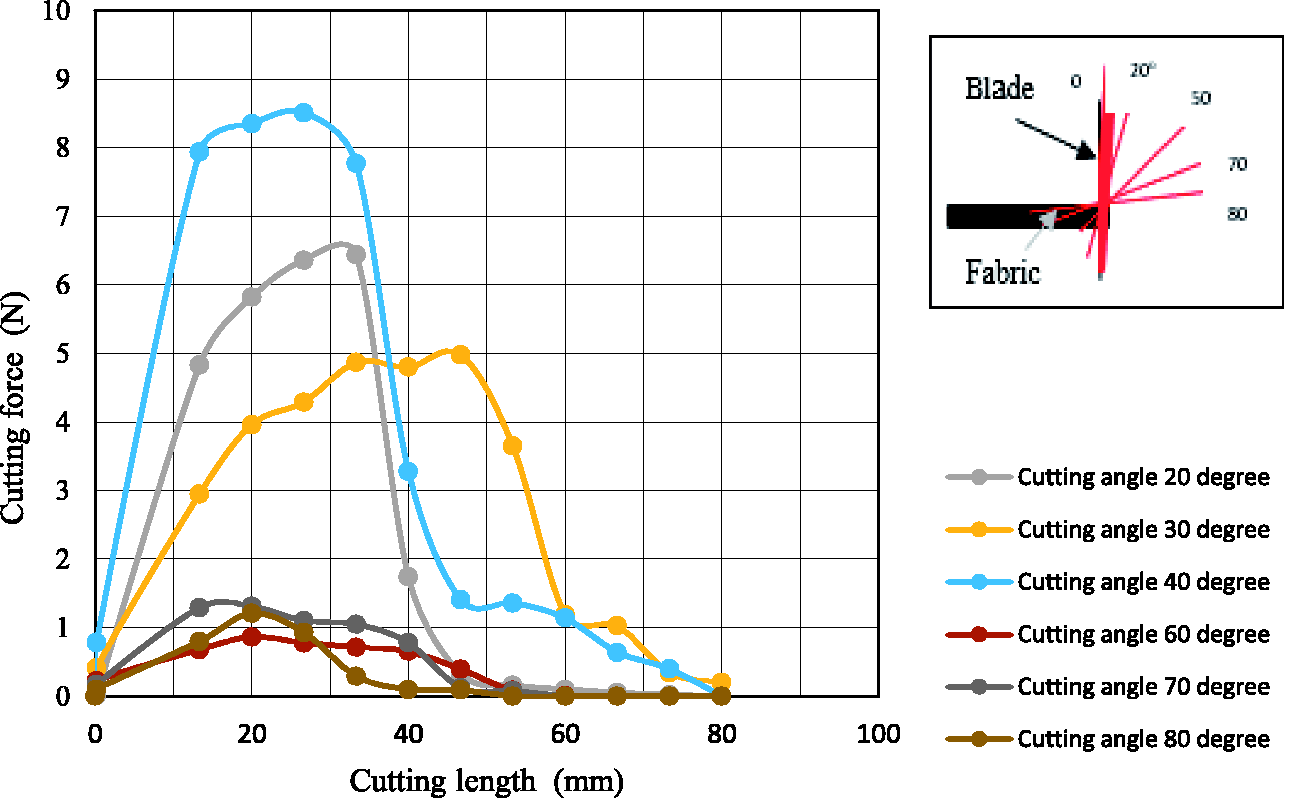
Values of maximum cutting force for different values of the cutting angle θ at cutting speed 100 mm/min.
The value of maximum cutting force decreases as the cutting angle θ increases because the cut length decreases, and a smaller number of yarns will be cut during the movement of the blade through the fabric. The increase of the normal load N will lead to an increase of the pressure between the blade and the sample at the point of contact as well as the stress σ y and σ z . Consequently, the textile and flexure stress increase, and the material will cut under the lower value of cutting force.
From Figure 13, both cut energy and cutting force decrease with an increase of the cutting angle. This is due to the fact the fabric will move on a longer length of the blade edge.
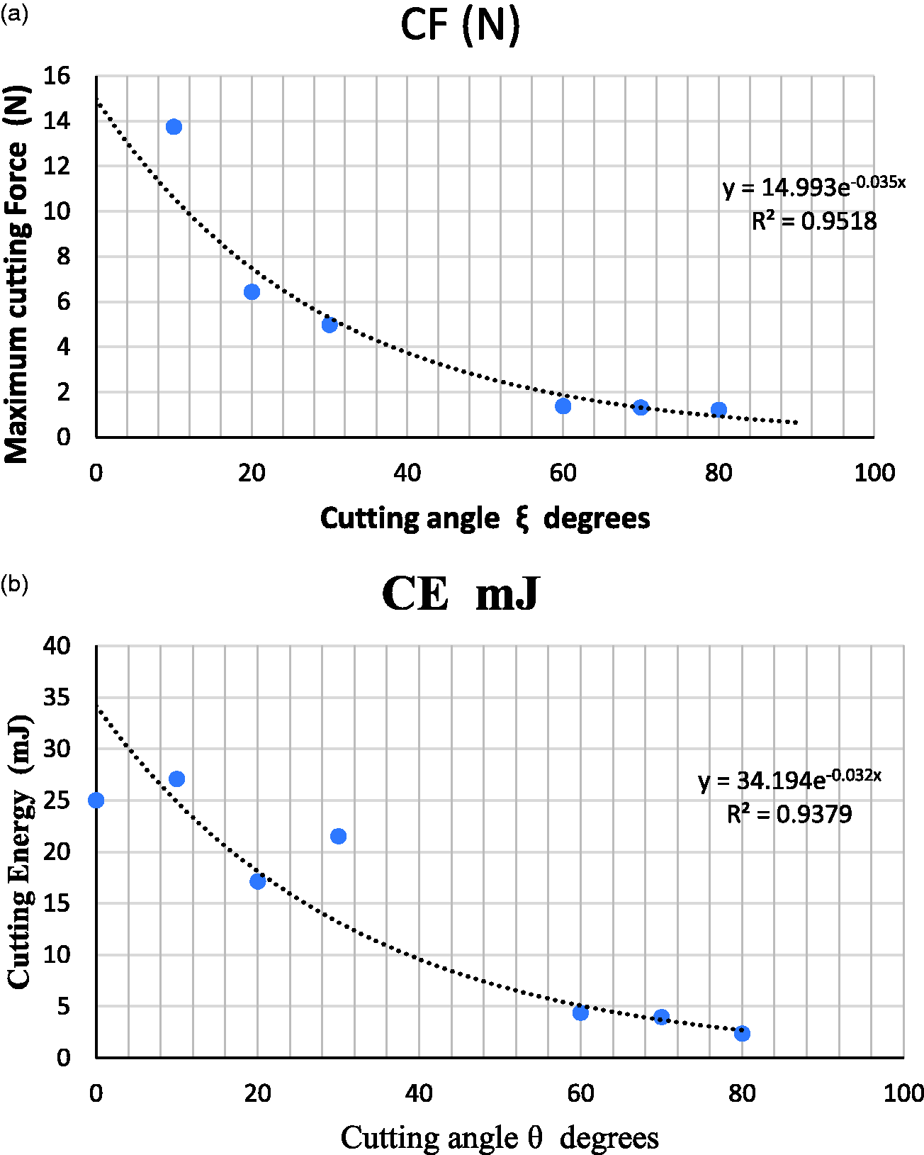
Value of maximum cutting force versus cutting angle at cutting speed of 100 mm/min: (a) cutting force; (b) cutting energy.
This drop depends on the structure of the fabric and the cutting force of the weft or warp yarns, as well as the direction of the cut. 23
The change of the cutting speed has a significant effect on the cutting force of the fabric. Figure 14 illustrates the effect of changing the cutting speed in the range of 100–210 mm/s. The maximum value of the cutting force was found to fall as the speed of cutting increases, Figure 15, showing the consequential effect of cutting speed on cutting force. The results have shown that with the increase in the cutting speed from 100 to 210 mm/s the maximum cutting force reduces from 5.4 to 1.4 [N]. The mechanism of spun yarn cutting under tension influences the value of the cutting force. 1 When the blade initially contacts the fibers, the yarn tension increases the stress between the outer layer fibers and the blade edge, causing a shear of the fibers, and the blade further penetrates in the successive layers of the fibers in the yarn cross-section. The yarn cutting resistance surges as the blade penetrates toward the yarn axis until it passes through it, then the cutting force drops until cutting of all the gripped fibers under shear and strain forces. At the same time, the cutting of the outer layer fibers will reduce the pressure on the other fibers in the inner layers, and slippage occurs. As the cutting blade penetrates further, the yarn loses its integrity, accelerating its failure. With the increase of the cutting speed, this mechanism will be accelerated, and a lower cutting force will be recorded. The integrity of the yarn depends on the coefficient of friction between the fibers in the yarn cross-section, which reduced as the cutting speed increased.
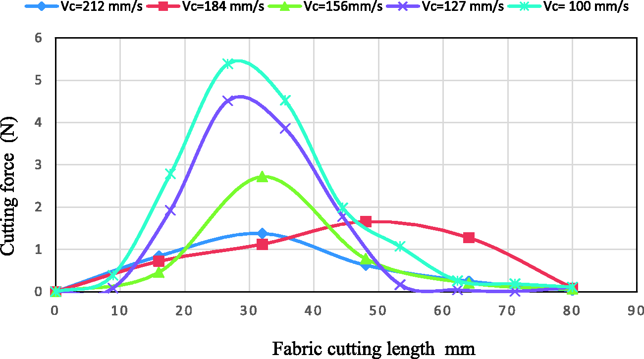
Cutting force versus fabric cut length, cutting angle zero.
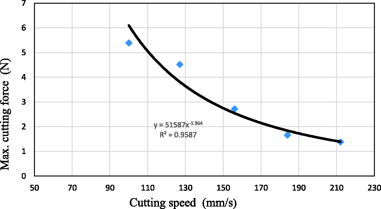
Maximum cutting force versus cutting speed, cutting angle zero.
Conclusion
The challenge facing protective fabric, when subjected to cutting forces, necessitates accurate measurement of the cutting force of the fabric under similar working conditions. A new design apparatus for measuring the cutting force for yarns and fabric was introduced. The analysis of the mechanism of cutting by the designed apparatus was given. This indicates that the yarns in the fabric are cut under the effect of shear stress, tensile stress, and flexural stress. In addition, the maximum cutting stress is a function of the yarn’s mechanical properties, the friction coefficient at the point of contact between the yarns and the blade, and the value of the normal force applied.
The unique features of this invention are as follows:
the material can be tested under various normal forces or cutting speeds; the cutting angle can be changed to simulate the conditions of cutting.
The measurement of the cutting force of fabric indicates that the cutting angle has a significant effect on the value of the maximum cutting force and the cutting energy; they fall significantly when the cutting angle decreases from 0° to 30°. It was revealed that the cutting speed has a highly significant effect on the cutting force. The results indicate that with the increase in the cutting speed from 100 to 210 mm/s, the maximum cutting force reduces from 5.4 to 1.4 [N].
Footnotes
Declaration of conflicting interests
The authors declared no potential conflicts of interest with respect to the research, authorship, and/or publication of this article.
Funding
The authors received no financial support for the research, authorship, and/or publication of this article.
