
Abstract
During the processing of covered yarn, the stability of the tension of the yarn unwinding from the package directly affects the quality of the covered yarn. In this work, a mathematical model of the yarn unwinding balloon was established, and the influence of Coriolis force and air resistance on the balloon was considered. Further, the balloon shape of the yarn at different unwinding linear speeds was studied. An experimental observation platform for the yarn balloon morphology was built. The comparative analysis of the balloon shape obtained using the experimental observation and the theoretical research results showed that the mathematical model of the yarn unwinding balloon is correct. The phenomenon of scratching the upper edge of the package during the unwinding of spandex should be avoided. Finally, in order to maximize the diameter of the spandex package, the taper of the core yarn bobbin and the minimum yarn guide distance was determined based on the guidance of the theoretical simulations and experimental analysis. The research results provide a design base for the layout and structural dimensions of the follow-up elastic fiber passive precision tension control device.
With the continuous progress of the textile industry and the improvement of people’s requirements for the comfort of clothes, elastic fibers are being widely used in socks, underwear, sportswear, and high elastic fashion due to their high elongation at break, low modulus, and high resilience. Further, they continue to expand into the automotive decoration, medical, aviation, and other fields. Spandex is the earliest developed and most widely used variety of elastic fiber with the most mature production technology. The spandex covered yarn has good elasticity, and the woven fabric is soft, comfortable, close to the body, and allows freedom of movement.
The covered yarns consist of mostly elastic fibers in the core and are wrapped with another filament in order to form a yarn with a new structure. They have characteristics such as uniformity in thickness, fluffiness, and plumpness. Further, they are also smooth with less hair with high strength, and minimal broken ends. The mechanical covered yarn continuously winds the outer covering yarn on the surface of the elastic core yarn, which is controlled at a certain draft ratio in a spiral manner. The continuous spiral winding forms a yarn with a certain twist, which is characterized by good elasticity, high strength, and good wear resistance. Further, its fabric style is flat and crisp and close to the body, but not very tight.
In the spinning process, the yarn tension has to be kept constant during the unwinding process in order to reduce the influence of the yarn tension fluctuations on the formation of the products. 1 When the yarn is unwinding, the quality of the unrolled yarn should not be reduced, unless this reduction does not significantly reduce the quality of the yarn products.2,3 After unwinding the package, the outer covering yarn is wound and covers on the surface of the core yarn. The unwinding process forms a yarn balloon. The unwinding tension of the yarn during unwinding is often affected by many factors, such as the yarn guide distance, unwinding speed, yarn characteristics, and the bobbin shape. In order to ensure the stability of the yarn tension while the yarn is unwinding at high speed, in this work, the influence of the yarn guide distance on the tension of the unwinding balloon was mainly studied, and the taper of the core yarn drum and the minimum yarn guide distance were determined.
The yarn structure, bobbin parameters, and unwinding process are the main factors that affect the unwinding tension. 4 Henry 5 derived the relationship between the unwinding tension and the adhesion and static friction in series while estimating the adhesion between the yarns. Fraser 6 elaborated and solved the unwinding form and yarn tension of linear elastic yarn in more detail. Fan et al. 7 conducted the corresponding numerical analysis on the small curvature balloon model. Pracek et al.8,9 studied the theory of yarn unwinding from the package and established a mathematical model for unwinding a cylindrical package, and analyzed how the winding angle affects the angular velocity and tension oscillation of the yarn during the unwinding process.
During the production of the covered yarn, Feng et al. 10 established a balloon model of the yarn unwinding in order to analyze the influence of the yarn tension, speed, balloon height, and turn-table radius on the balloon shape. Feng et al. 11 studied the relationship between the draft ratio of the covered yarn and the yarn tension and proposed a new type of covered yarn system that could control the stretching tension of the spandex elastic yarn.
In this work, the influence of Coriolis force and air resistance on the unwinding yarn was established, and the mathematical model of the unwinding yarn balloon and the corresponding motion equation was established. Further, the Runge–Kutta method was used for the numerical solution, and the unwinding yarn was simulated and analyzed. Furthermore, an experimental test platform for the shape of the unwinding yarn balloon was established and the trajectory of the balloon of the moving yarn was measured. By comparing the balloon shapes that were obtained using simulation, the taper of the core yarn tube and the minimum yarn guide distance were determined.
Processing of the covered spandex yarn
The mechanically covered yarn machine is one of the main items of equipment for processing covered yarn. A schematic representation of the covering principle is shown in Figure 1.
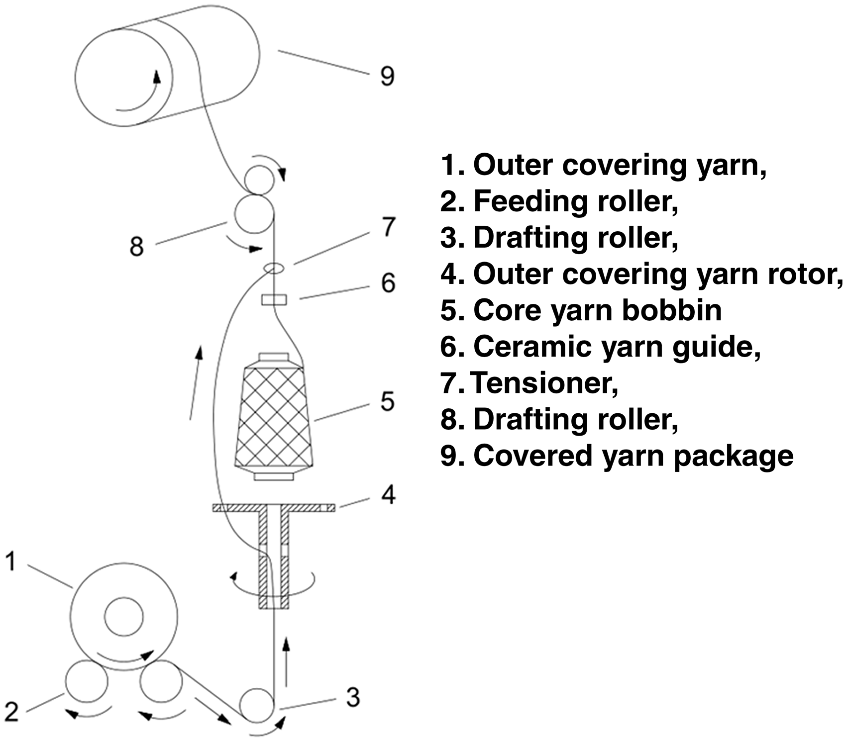
Schematic representation of the mechanical covered yarn machine.
In Figure 1, the elastic core yarn passes through the hollow spindle and is drawn between the feeding roller, 2, and the drafting roller, 8. Then, the outer covering yarn is inverted and formed on the rimmed bobbin, and the hollow spindle rotates with the outer covering yarn rotor, 4. After the outer covering yarn is thrown out of the rimmed bobbin to form a balloon, the core yarn is spirally wrapped at the ceramic yarn guide, 6, and finally, the covered yarn is formed. After being sent out by the drafting roller, the covered yarn reciprocates regularly through the traverse guide device at a certain overfeed rate, and is finally packaged on the covered yarn drum.
Mathematical model
The system model of the covered spandex yarn, the constitutive relation, and the establishment of the elastic yarn balloon are discussed below.
System model of the covered spandex yarn
For the convenience of research, this paper uses two coordinate systems in order to define the spatial form of the elastic yarn balloons, namely the fixed coordinate system Г(r, φ, z) and the rotating coordinate system W(r, θ, z). Their origins are located at the center point O of the ceramic yarn guide, and the Z-axis coincides with the central axis of the bobbin. Moreover, the rotating coordinate system W rotates around the Z-axis at an angular velocity ω, as shown in Figure 2.
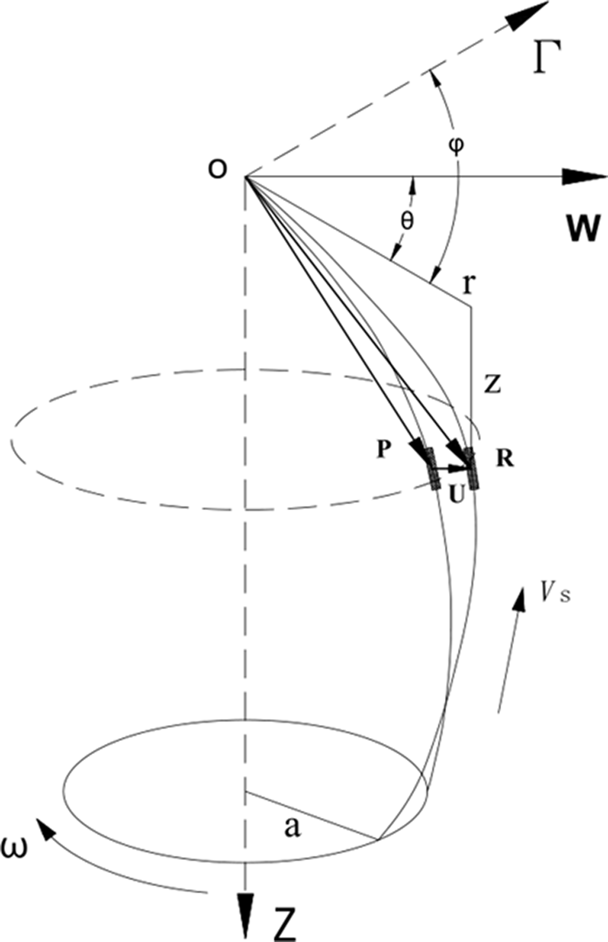
Space coordinate system of yarn unwinding balloon model.
In Figure 2, the vector

Constitutive relation
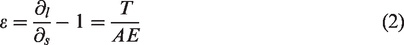
The ratio of the elongation of the yarn to the original length of the yarn is the strain of the yarn. Generally, yarns whose initial modulus strain is less than 5% are considered to be linear elastic yarns, such as cotton and polyester. Yarns with a strain greater than 5% are considered as non-linear elastic yarns, such as viscose fibers and elastic fibers. For linear elastic yarns, the Young’s modulus of the yarn at
For non-linear elastic yarns, the Young's modulus is no longer constant, but rather changes with the yarn tension and strain. The relationship between the yarn tension and strain is mainly reflected in Equation (3)

Therefore, the strain expression of non-linear elastic yarn is obtained as shown in Equation (4)
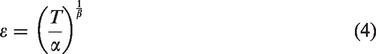
In Equation (4), α refers to the initial modulus of the non-linear elastic yarn and β refers to the nonlinearity of the non-linear elastic yarn; α and β are determined according to the tension–strain curve of the elastic yarn.
Establishing the elastic yarn balloon
The micro-elements

In Equation (5),
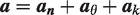
As the elastic yarn is deformed during the unwinding process, the linear density on vector

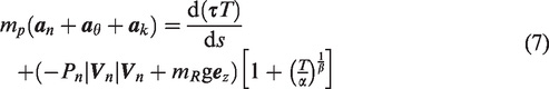
In Equation (7),
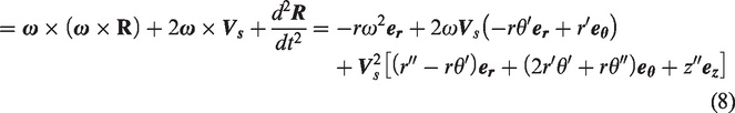
When the bobbin radius at the unwinding position is a, and the height of the unwinding balloon is H, according to the dimensionless parameters given by Fraser, the above parameters are defined as dimensionless (Equation (9))
In Equation (9),
The strain of elastic yarn is expressed as shown in Equation (10)
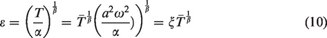
In Equation (10),
As the dimensionless

In Equation (11),
The boundary conditions are as follows: at the origin O of the ceramic yarn guide,
Experiments for the parameters
Due to the dynamic characteristics of the spandex unwinding process, in this work, the dynamic drafting of the spandex through the roller drafting system of the traditional mechanical covered yarn machine was determined. In this way, the corresponding tension value of the spandex at different draft ratios was determined, and then the tension–strain curve was fitted to obtain the values of α and β.
The experimental conditions were as follows. The ambient temperature was 22°C; the relative humidity was 65%; the three specifications of the spandex yarn cakes of 20, 30, and 40 denier were produced by the same manufacturer.
The experimental equipment includes the roller drafting system of a mechanical covered yarn machine and an ETPX-B dynamic monitoring tension meter that was manufactured by Hans Schmidt, Germany, with a maximum range of 100 cN and accuracy of 0.1 cN.
The experimental process was as follows. The roller drafting system of the mechanically concealed yarn machine was used to realize the feeding, drawing, and winding of the spandex yarn. In order to avoid the influence of the conveying speed on the measurement accuracy, the unified conveying speed of 22 m/min was adopted. Further, through replacement, the change wheel of the drafting roller system realized the adjustment of different draft ratios, and thereafter, the dynamic monitoring tension meter was used to sample the data for 10 minutes, and the average tension value under each draft ratio was obtained as shown in Table 1.
Relationship between the tension and draft ratio of the spandex
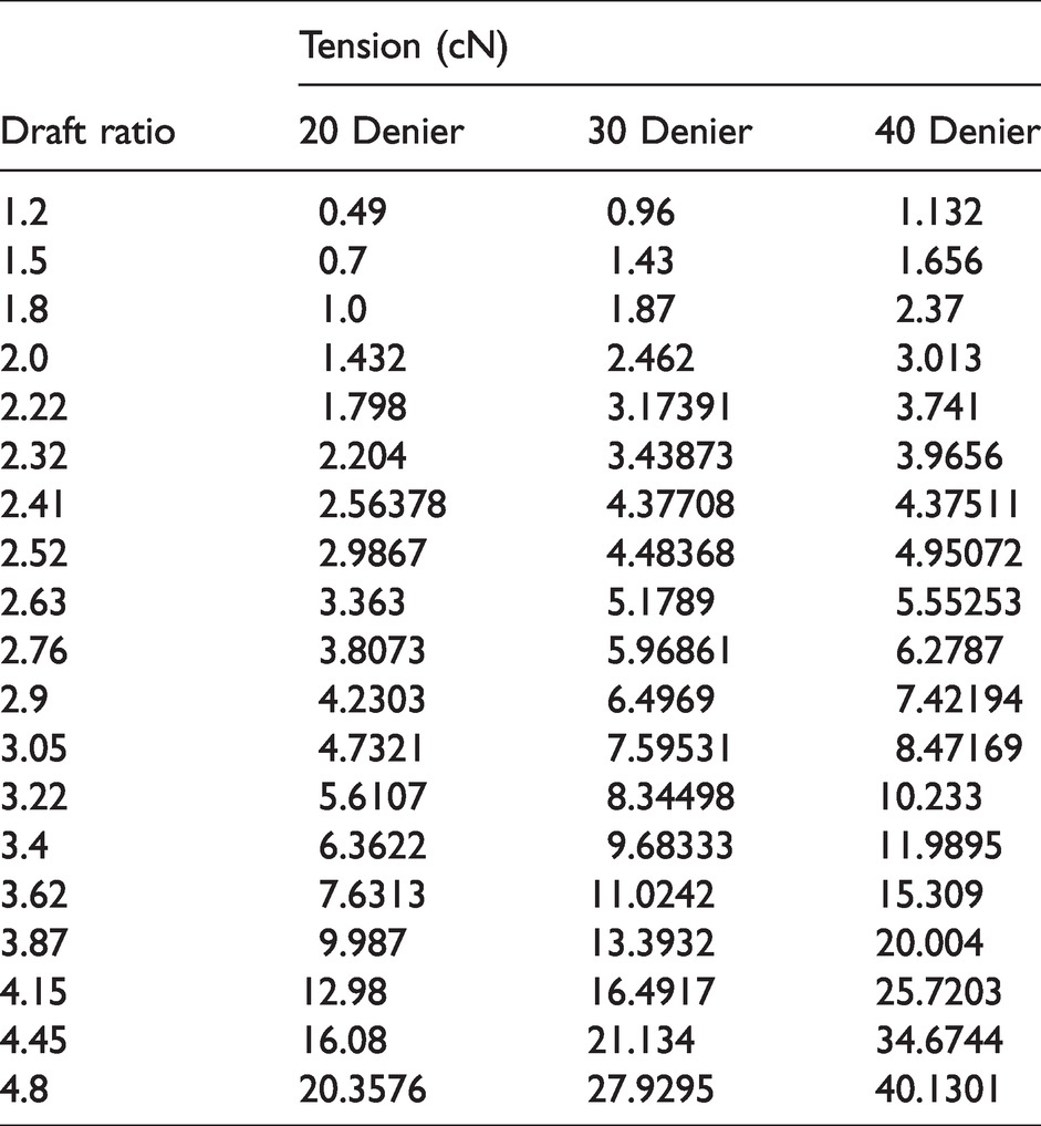
According to the data in Table 1, it is observed that the initial modulus of spandex is found to be relatively small, and the drawing deformation is achieved under very small tension. At a lower draft ratio, the relationship between spandex tension and the draft ratio is almost linear. It is also found that as the draft ratio gradually increases, the spandex tension also increases. In the critical draft zone, the spandex tension and the draft ratio are in line with the parabolic relationship. Further, when the draft ratio exceeds the critical draft zone, the relationship between spandex tension and the draft ratio conforms to the power function curve. The spandex tension–strain curve is drawn by fitting, as shown in Figure 3.
Tension–strain curve of spandex.
In Figure 3, the α values corresponding to 20, 30, and 40 denier respectively are 0.6055, 0.8827, and 0.9956 cN/D, that is, 5.45, 7.94, and 8.96 cN/tex, respectively. The β values are 0.3848, 0.3980, and 0.3614, respectively.
Results and discussion
In order to avoid friction between the spandex and the edge of the bobbin, the experiment was carried out using a bobbin with a taper of 3.5°, the spandex winding angle was 12°, and the full bobbin diameter was 48 mm. For the convenience of observation, the distance between the upper edge of the bobbin and the yarn guide was set to 150 mm. The elastic fiber used in the experiment was 30 denier spandex.
MATLAB was used to numerically solve Equation (11) by the Runge–Kutta method. The initial condition was
In order to describe the unwinding morphology of the elastic yarn in a better way, the morphological parameters
Effects of the drafting speed and the winding radius on the shape of the spandex balloon during unwinding
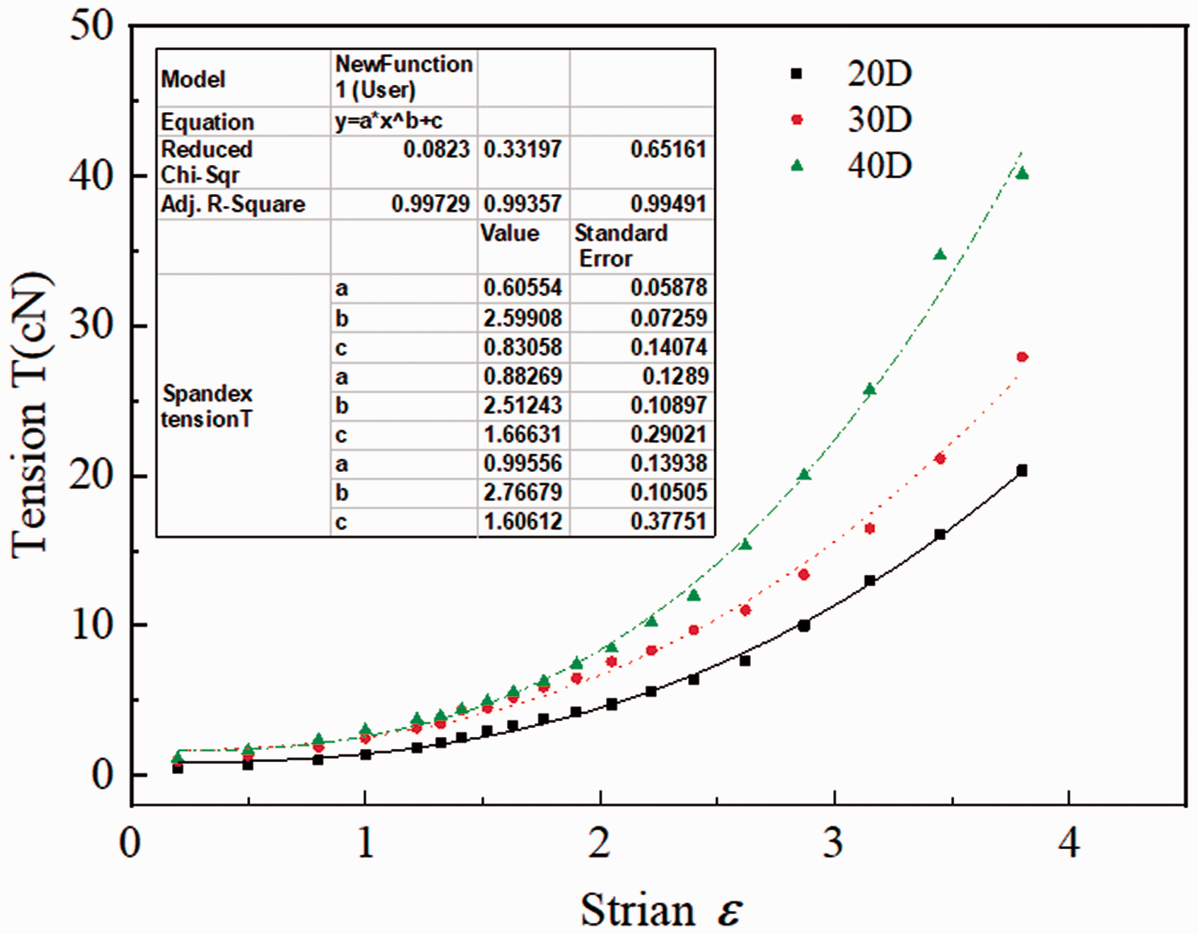
The rotational angular velocity of the unwinding of spandex was mainly determined by the drafting speed. It is found that when the drafting speed is high, the rotational angular velocity of unwinding is also high. This affects the unwinding tension and the elastic deformation of the spandex, which was finally reflected in the influence on the shape of the unwinding balloon. With the continuous unwinding of the spandex, the package radius is found to become smaller layer by layer. When the drafting speed was constant, the rotational angular velocity of the unwinding balloon is found to gradually increase, which would affect the shape of the unwinding balloon. In Figure 4, R is the bobbin radius. This paper simulates the balloon shape when the bobbin radii were 24, 20, and 17.5 mm, respectively, at the drafting speeds of 50, 100, 200, 300, and 400 m/min (Figure 4), respectively.
The simulated balloon shape of spandex unwinding under different drafting speeds and bobbin radii. (a) Drafting speed 50 m/min; (b) drafting speed 100 m/min; (c) drafting speed 200 m/min; (d) drafting speed 300 m/min and (e) drafting speed 400 m/min.
In order to compare with the shape of the spandex unwinding balloon obtained using the simulation, the actual balloon shape was observed under the above-mentioned experimental process parameters. In order to compare the actual and simulated unwinding balloon shapes more clearly, Figure 5 shows the unwinding balloon shape when the draft speed was 400 m/min with different package radii.
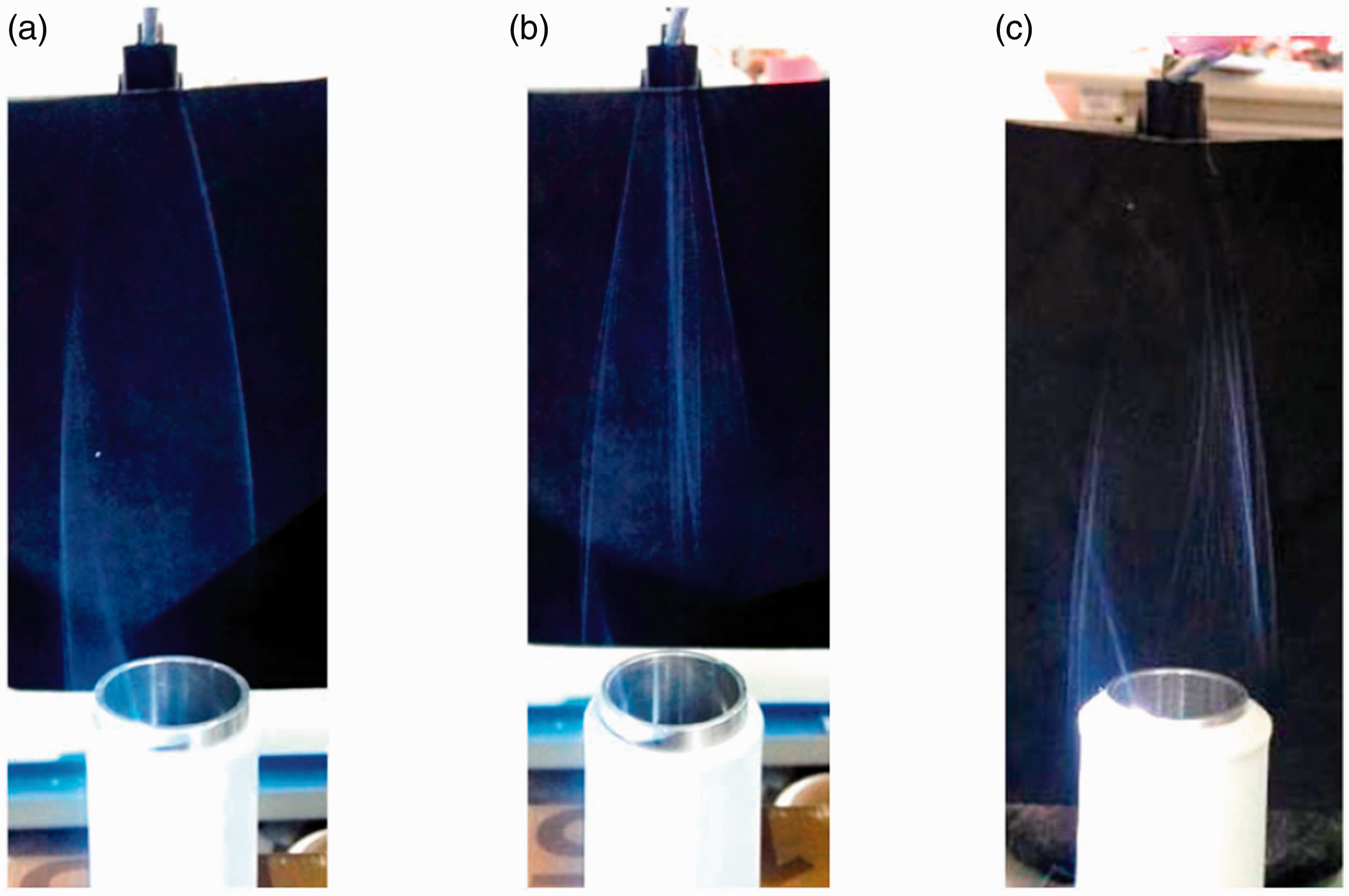
The actual balloon shape of spandex unwinding under different drafting speeds and bobbin radii. (a) Bobbin radius 17.5 mm; (b) bobbin radius 20 mm and (c) bobbin radius 24 mm.
From Figure 4, it is observed that at low drafting speeds, the unwinding angular velocity is small, and due to the elastic deformation of spandex, the balloon formed by unwinding is tapered. It is also observed that as the drafting speed increases, the unwinding angular speed also continues to increase, and the unwinding balloon begins to expand. When the drafting speed reaches 300 m/min, the maximum radius of the unwinding balloon is found to be already greater than the radius of the corresponding spandex tube. At the same drafting speed, when the radius of the spandex bobbin is less and the unwinding angular velocity is high, the unwinding balloon is found to expand more. This phenomenon is especially obvious when unwinding occurs at a high speed. The morphological parameters of the unwinding balloon obtained by simulation and actual observation are shown in Table 2.
The morphological parameters of the spandex unwinding balloon under different drafting speeds and bobbin radii
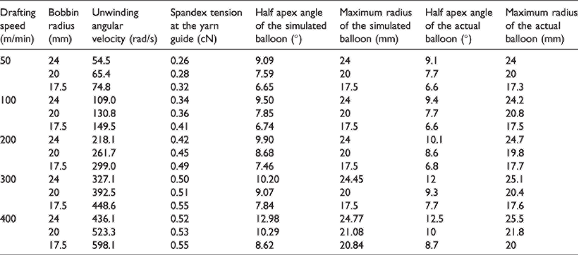
The comparison between the simulated value and the actual value in the table shows that when the radius of the spandex bobbin is 24 mm, the half apex angle and the maximum balloon radius obtained by the simulation and the experimental observation are the same at each drawing speed. When the spandex bobbin radius is 17.5 mm, the experimentally observed balloon half apex angle is generally smaller than the simulated value at various drafting speeds. This is mainly because, during the spandex bobbin winding process, the tension of the bottom layer is slightly greater than the tension of the outer layer.
Effect of spandex balloon height on the balloon shape during unwinding
The forming process conditions of the spandex yarn bobbin determine that the spandex unwinding is peeled from the yarn bobbin layer by layer, and the unwinding position changes periodically. In Figure 6, H is the corresponding unwinding balloon height. Therefore, the corresponding unwinding balloon height also changes periodically. When the bobbin radius is 24 mm, the drawing speeds are found to be 50, 100, 200, 300, and 400 m/min, and the spandex balloon heights are found to be 150, 200, and 250 mm, where the balloon shape is simulated (Figure 6).

The shape of spandex balloons at different unwinding heights. (a) Drafting speed 50 m/min; (b) drafting speed 200 m/min; (c) drafting speed 100 m/min; (d) drafting speed 300 m/min and (e) drafting speed 400 m/min.
From Figure 6, it is observed that when the unwinding height increases, the maximum diameter of the spandex unwinding balloon decreases. In particular, when the drafting speed is low, the spandex yarn at the lower part of the bobbin scratches the upper edge of the bobbin when it unwinds. This phenomenon is likely to cause periodic fluctuations in the unwinding tension of the spandex, and the spandex will be damaged when it is scratched against the upper edge of the package.
In order to avoid the phenomenon of scratching the upper edge of the tube when the spandex is unwinding, and at the same time to ensure that the spandex capacity is maximized, in order to reduce unnecessary joints in the mechanical coating process, a core yarn tube with a taper of 5° was selected. Based on the guidance of the above theoretical simulation, a large number of experimental analyses were carried out. Further, a core yarn tube with a taper of 5° was selected in order to ensure the stability of the yarn tension while the yarn is unwinding at high speed. The forming process conditions of the spandex yarn bobbin determine that the spandex unwinding is peeled from the yarn bobbin layer by layer, and the unwinding position changes periodically. The unwinding height increases and the maximum diameter of the unwinding air coil of the spandex decreases. The guide distance should be greater than 25 mm through experiments and simulations. When the bobbin radius is 24 mm, the minimum distance between the upper edge of the bobbin and the guidewire porcelain piece of the tension control device, that is, the minimum guide distance, should be 25 mm.
Conclusions
In this work, a mathematical model of the unwinding yarn balloon in covered yarn was established, and an experimental test platform for balloon morphology was built. The morphology of the yarn balloon was studied using numerical simulation and experimental testing. The following conclusions are obtained.
(1) The relationship between the spandex tension and the draft ratio was determined using experiments, and the non-linear elastic parameters of spandex were obtained using fitting, thereby simulating the shape of the unwinding balloon under different unwinding states. (2) During the unwinding process, friction between the spandex and the edge of the bobbin should be avoided. By comparing the simulated balloon shape with experimental tests, it was determined that the taper of the core yarn tube was 5° and the guide distance should be greater than 25 mm. Under this condition, the capacity of the spandex package was maximized, and the phenomenon of scratching the upper edge of the package during the unwinding of spandex was avoided.
Footnotes
Declaration of conflicting interests
The author(s) declared no potential conflicts of interest with respect to the research, authorship, and/or publication of this article.
Funding
The author(s) disclosed receipt of the following financial support for the research, authorship, and/or publication of this article: This work was supported by the National Natural Science Foundation of China (grant number 52103355) and the Fundamental Research Funds for the Central Universities and Graduate Student Innovation Fund of Donghua University (grant number CUSF-DH-D-2019095).