



Abstract
This paper focused on the investigation of the slub yarn parameters and the relationships of the aerodynamic friction along the surface of the slub yarn. The calculation of the frictional drag force was analyzed for spun yarns, which proves it has an irregular surface due to the irregularity of the yarn diameter along its length. In the case of slub yarns, the main descriptive parameters such as slub length, slub distance, slub multiplier, and base yarn count, will affect the air drag coefficient. A methodology for the calculation of the coefficient of air drag along the yarn in an airstream was developed for both regular and slub yarns under different conditions. The air frictional drag coefficients of yarn samples were calculated accordingly. Finally, empirical equations were developed. Calculations of the air friction drag coefficient of slub yarn were determined. The experimental results agreed well with the model predictions and showed that the present model had a high prediction accuracy.
On air-jet looms, the weft yarn of diverse types (spun yarn, plied yarn, slub yarn, chenille yarn) can be inserted. The insertion time is usually a function of the loom speed. The smaller the insertion time the higher the air velocity required, which increases the forces on the yarn during insertion and yarn breaks after insertion. Air-yarn friction force depends on several machine and yarn parameters,1–3 as well as the end breaks.4,5 A study of the effective parameters of weft yarn motion by simulation analysis in a single nozzle air-jet loom 5 deduced the pull force formula of the main nozzle on the air-jet loom and introduced the method of an experiment to test the airflow velocity at the exit of the nozzle. The equation for weft yarn motion was developed by using differential equations of air velocity distribution and air-yarn friction coefficient. A theoretical model is suggested to describe the weft yarn motion, that is, yarn displacement, yarn velocity, and yarn tension.6–8 Modification of this simulator with automatic data acquisition and analysis was used.9,10 The orthogonal test method and numerical simulation optimize the structure of the subsonic acceleration zone. 11 The yarn characteristics are thought to have the most effect on yarn velocity, air pressure, nozzle settings, and shed opening timings, and are likely to affect the failure of weft transfer during picking. 12 The value of the coefficient of the air drag force has been studied by several researchers.6,10,13– 16 Several authors have dealt with the theoretical investigation of the simulation of a yarn launched by the main nozzle of an air-jet weaving loom.17–19 Another parameter is the unevenness of the yarn diameter, which added another factor that complicates the determination of air drag force on the yarn.
Slub yarn can form a special appearance on the surface of the fabric and is used in the textile industry to produce primarily denim fabric, clothing and upholstery fabric, and is widely used in garments and decorative fabrics. The special appearance is determined by the different parameters of the slub yarn. To calculate the value of the yarn tension on the air-jet loom when using a slub yarn, the value of the coefficient of air drag must be known. It is a function of the Reynolds number (Re) which is not fixed on the various parts of the yarn during insertion. It is known that the main descriptive parameters of slub yarn (slub length, slub distance, slub multiplier, base yarn count, twist level, etc.) affect the strength and elongation performance of the fabric and its appearance. The theoretical profile of ring-spun slub yarn was studied. A mathematical model for the yarn count of ring-spun slub yarn was established to predict the yarn profile based on process parameters such as the fiber length, the velocities of rollers, and the time of over-feeding. A theoretical model of the air drag force along the yarn length with variable diameters and along the slub length in the airstream was developed. 20 A drag coefficient is a number used to model all the complex dependencies of yarn shape, surface conditions, inclination, and flow conditions. Several equations for the determination of an air drag coefficient were experimentally driven for normal yarn insertion. However, in the literature, there is a lack of information about the behavior of the insertion of slub yarns on air-jet looms, which is the main concern of this paper. In this work, a methodology for the calculation of the coefficient of air drag along the yarn in an airstream was developed for both regular and slub yarns, under different conditions. The effect of the air pressure on the coefficient of air drag was investigated.
Materials and methods
Materials
Several types of ring-spun yarns were tested as normal yarn and slub yarn, Figure 1(a), with different counts and structures as shown in Table 1 according to ASTM-D1907. Several yarns were produced with slubs of λ5 cm, L2 cm, λ10 cm, L2 cm, and λ15 cm, L2 cm.

(a) Slub yarns samples and (b) schematic design to measure the air drag force of yarns.
Types of different yarns with different counts and structures

Test set-up
A yarn is inserted into a glass tube of length 1500 mm and diameter 50 mm and held from one end into a tension force transducer, and then passed into a nozzle, and the other end is attached to a weight to perform a pretension of 0.5 g/tex. The yarn is exposed to the airflow in a single-channel main nozzle. The air pressure regulator controls the amount of air in the nozzle as shown in Figure 1(b). As the yarn is exposed to the airflow, tension in the yarn occurs. The flow of the air can be adjusted, and the change of yarn tension was measured using a strain gauge and the readings were recorded.
In each test, 10 yarns were fed, and the air drag force was measured at different values of the air pressure.
Measurement of yarn diameters
The yarns usually have an irregular diameter. The yarn diameter is highly varied over its length. 21 The analysis of the measurement of 22,000 cross-sections along the yarn length, ID 5, indicated the high variability of yarn diameter as illustrated in Figure 2. Figure 3 shows the frequency diameter distribution of single yarns, representing the usual pattern of yarn diameter variation along the yarn length. 22 The diameter of ring-spun yarns was measured on the Quick Quality management QQM3 instrument at the Faculty of Textiles laboratory of the Technical University of Liberec, Czech Republic. 21
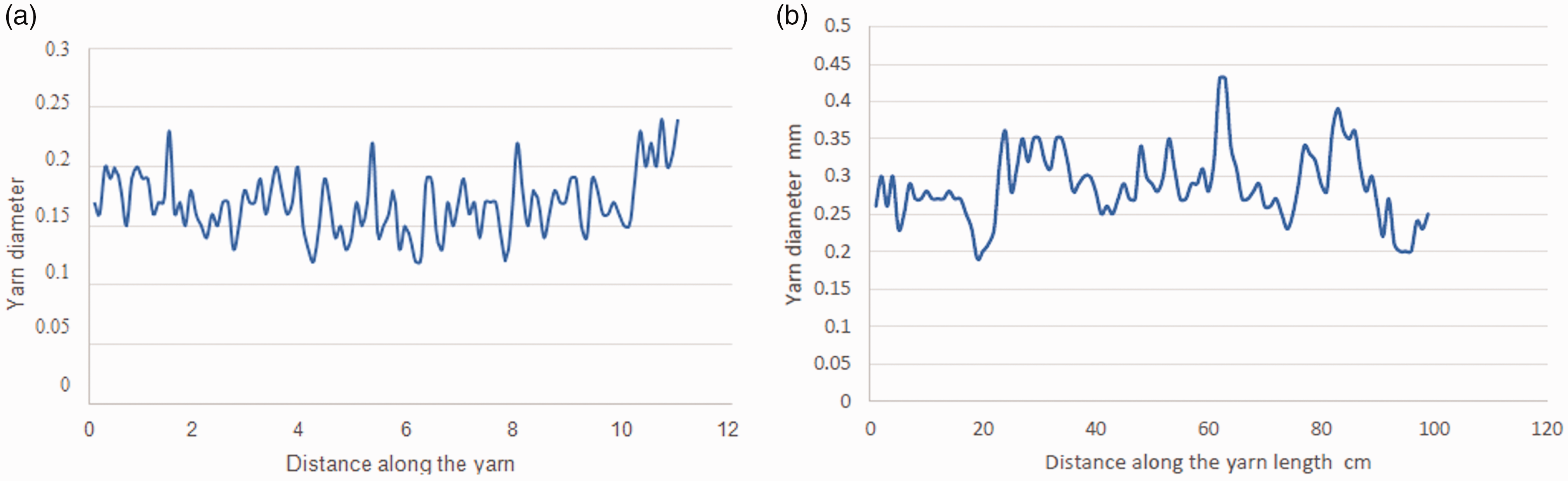
Variation of yarn diameter along its length.
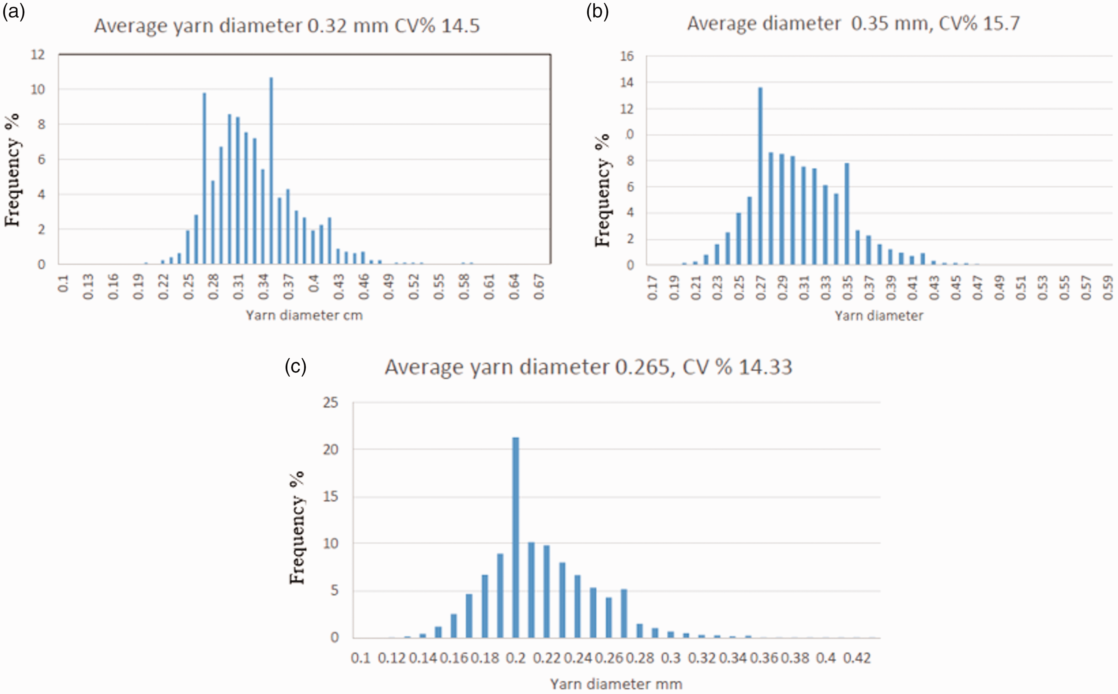
Frequency distribution of single yarn diameter.
Figure 3 shows the high variability of the yarn diameter (CV% 15–18), which will affect the movement of the yarn in the air stream.
Results and discussion
The air drag force of single yarns
The air drag force of single yarns is dependent on the coefficient of air drag, which, in its turn, depends on several factors such as the Reynolds number, surface roughness, yarn irregularity, yarn porosity, and type of fiber. Besides the change in the diameter, the spun yarns are hairy. Skin friction of the yarns, which is a function of the yarn hairiness, is another factor that affects air drag force. 23 It was found that the air drag coefficient decreases gradually with the increase in the number of yarn faults such as thick places, thin places, and neps. 24 The average yarn diameter is used for determining the theoretical values of air drag force. The measurements of the air drag force for the different samples are shown in Figure 4. It was revealed that with the change in the air pressure from 1 bar to 5 bar, the value of air drag force changes exponentially for different yarn types.
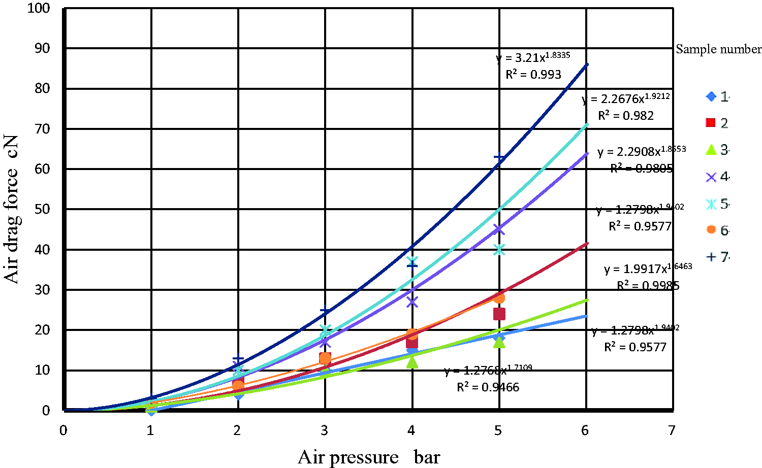
Measured air drag force versus the air pressure of different yarns.
As the air pressure increases, the drag force increases. In the case of spun yarns and slub yarns, the value of the air drag force will change according to yarn irregularities and the parameters of slub yarn as well as the yarn surface roughness. The coefficient of air drag was calculated for several yarns and was found to be proportional to Re0.59. The measurement of the air velocity distribution along the tube length was found to be at different air pressure (p):
4

The equation of motion for the weft slub yarn can be driven by the calculation of several factors affecting the weft air drag force.
Procedures of calculation
Calculate the resultant diameter of the slub yarn equation. Calculate the air velocity along the yarn length taking an increment of dx cm, p is air pressure (bars) at the nozzle, and X
i
is the distance from the nozzle exit. Calculate the value of the Reynolds number at different sections along the yarn:
4. Calculate the value of the coefficient of air drag at different sections along the yarn:
5. Calculate the value of air drag force at each yarn section:
where di is the yarn diameter at section i, and γ is kinematic viscosity (for air 1.6 * 10−5 m2/s).

where k is constant depending on yarn specifications and Cdi is the coefficient of air drag.

where ρ is the air density (1.225 kg/m3) and dFi is the air drag force.
Then calculate the value of the air drag force on the yarn of length 2 cm at different positions along the yarn length.
6. The total calculated air drag force on the yarn = ⅀Fi, where C is constant depending on the yarn specifications. 7. Measure the value of the total yarn tension for the total length of the yarn inserted in the tube under a pretension to keep it straight during the testing. 8. If the total measured air drag force and calculated air drag force are not equal, an iteration procedure was used to get the value of C that makes them equal.
The theoretical calculation of the air drag force
Figure 5 shows the theoretical calculation of the air drag force on several types of yarns.
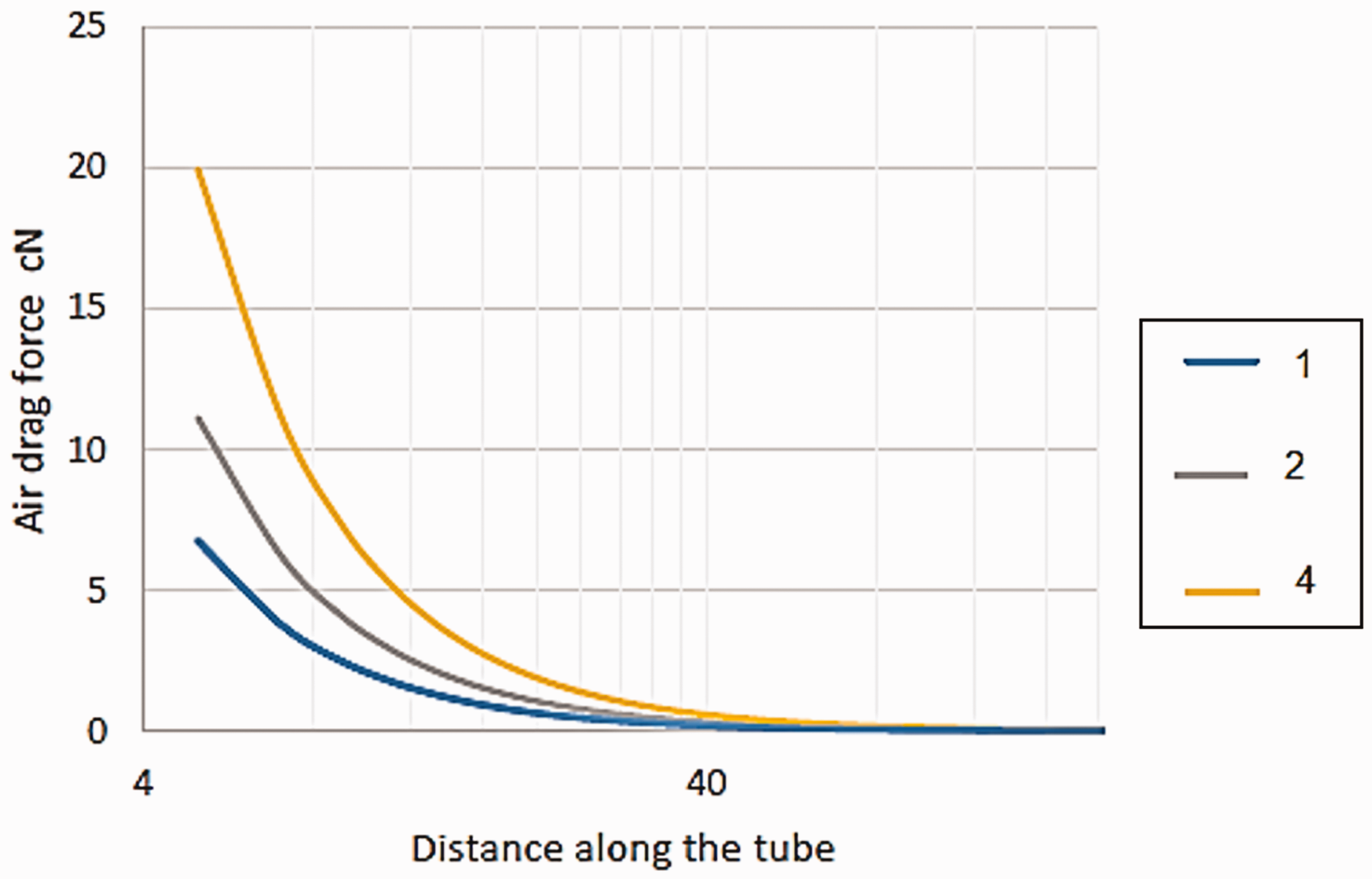
Theoretical air drag force for several types of yarns at length 2 cm and air pressure 5 bar.
Figure 6 shows the values of the calculated air drag force versus the measured air drag force. Measured air drag force on the yarn at different pressures was found to be highly correlated with the theoretical values. Statistical analysis at a 95% level of confidence shows that there is no significant difference between the average total yarn tension of theoretical and experimental results. With the good agreement between the theoretical values of the yarn air drag force and the experimental results, the suggested methodology is suitable for the prediction of the behavior of yarn in the insertion zone. For this purpose, the equation has been developed for weft yarn motion. The total air-yarn friction force is:

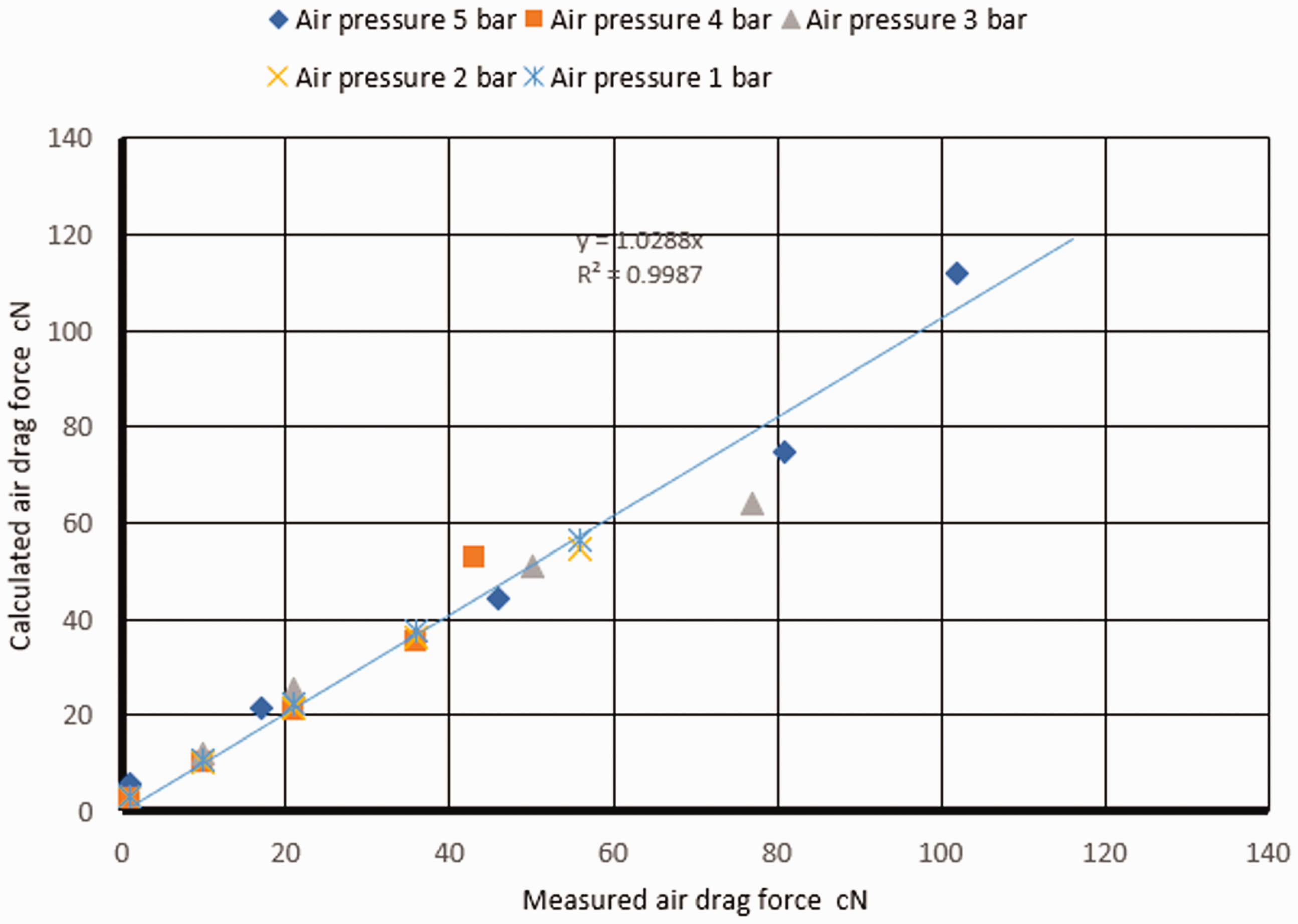
The calculated air drag force versus the measured air drag force of the yarn.
Due to the variability of air velocity along the yarn length, the value of Re will be different, corresponding to the values of Cd. The calculated values of Cd, as a function of the Reynolds number, are shown in Figure 7 for different yarns without slubs. It was found that the air pressure affects the Re value, especially at low air pressure. The high value of the air pressure will increase the value of the air velocity, and therefore affect the value of the friction force created from the contact of the yarn and the air.6,25–30 In the meantime, the increase of the air velocity leads to a change in the yarn surface hairiness reducing the yarn skin friction coefficient.
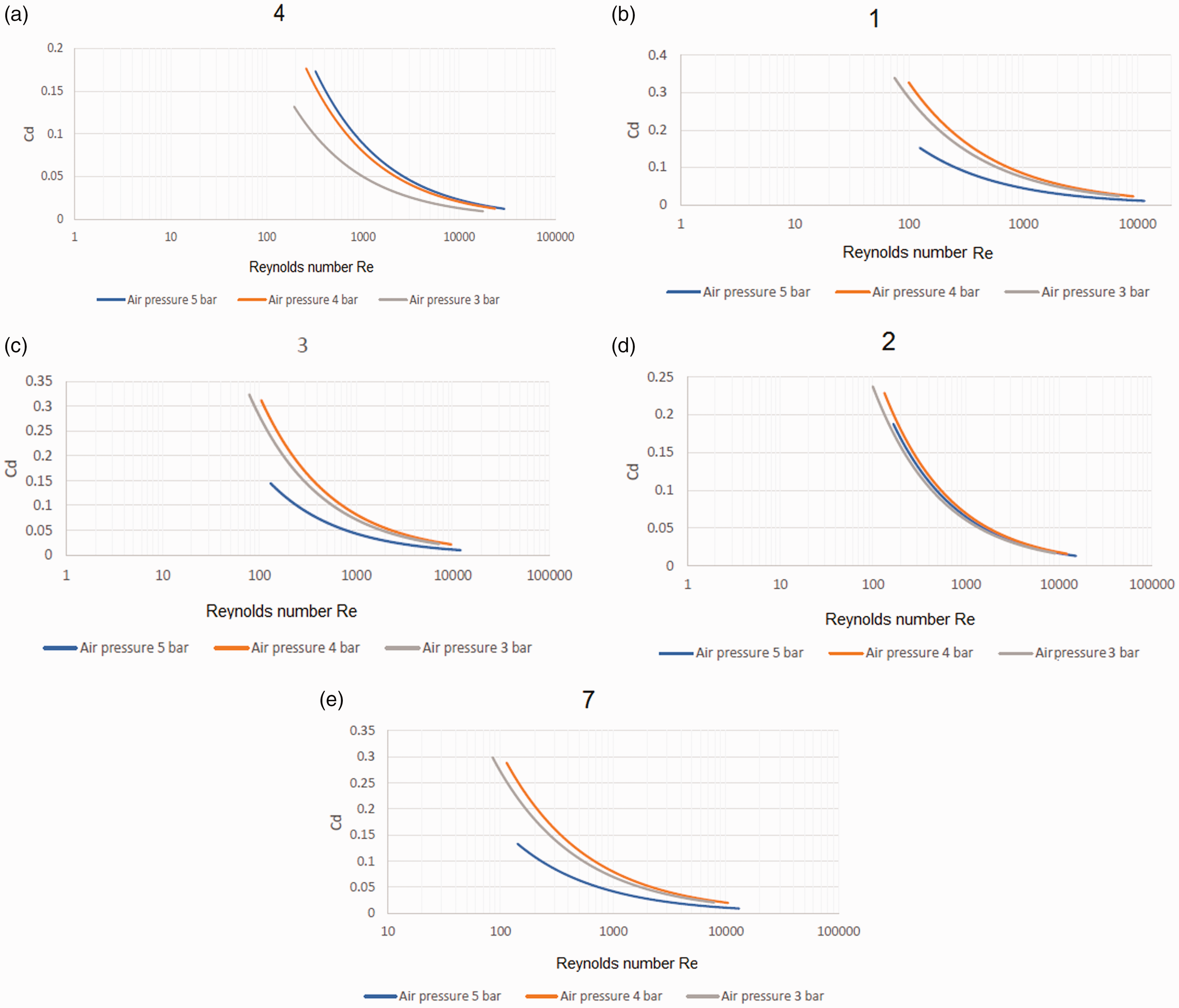
Coefficient of air drag versus Reynolds number at different air pressures.
Due to the variability of air velocity along the yarn length, the value of Re will differ, and consequently, the values of Cd. The calculated values of Cd, as a function of the Reynolds number, were tackled by several authors, and each one deduced a different formula.6,31 As the air pressure increases its velocity also increases. The value of the Reynolds number (Re) will also increase, reducing the value of the Cd; 6 this probably happens at high-pressure values. The value of Cd alsodepends on the type of fibrous material. It was found experimentally that the relationship between the air friction coefficient and air velocity was C f = c1 V− c 2, where c1 = 0.4193 and c2 = −0.4883 for cotton yarn; c1 = 0.4274 and c2 = −0.4887 for textured polyester yarn.6,32
Another factor affecting the value of the air-drag force is when the yarn is allowed to vibrate in the air stream leading to an increase in the air-drag force value.
33
That can occur because of many factors that control the airflow in the tube. The initial pressure is a determining factor for pressure distribution along the yarn path and, consequently, the elemental friction force applies to the elemental surface of the weft. An empirical equation that expresses the Cd was assumed as:

The fitting experimental data of the different yarns gives the following:

Constant Kcd depends on the fiber type and yarn structure and is given in Table 2.
The values of constant Kcd for several types of yarns

The transfer of weft yarn also has its complications, especially in the case of staple yarns. The weft yarn air drag force is provided by the friction between the yarn surface and the air stream, both are variable along the tube length and cannot be controlled. The airflow through the tube as well as the behavior of the yarn in the flow is complicated, especially when using a slub yarn.
Air drag force in the case of slub yarn
A simple slub yarn structure is composed of two parts: the base part and the slub part. Slub yarn can be considered as a regular change of the yarn diameter. Figure 8 represents the geometrical parameters of the two slub parts; the changes could be in the diameter of the slub, slub length, or slub distance. The influence of short slub yarn faults on drag coefficient was studied. It was found that the rate of change for the coefficient of drag force increased first and then verged to stabilization gradually with the diameter of yarn faults increasing. In addition, the change rate for the coefficient of drag force presented a descending tendency gradually with an increase in the number of yarn faults.25,27

General slub yarn design.
In the case of slub yarn, the diameter is not constant and varies along the yarn. The slub also may have the same diameter or different diameters along the yarn length with periodical equal distance or it may be variable, depending on the slub distribution desired pattern for the final fabric, either woven or knitted fabric. In this analysis, the slub yarn may be considered as yarn with a count equal to the resultant count of the slub yarn. A simple slub yarn structure is composed of two parts – the base part and the slub part. Let us assume that the slub yarn consists of two portions as shown in Figure 8.
The resultant count of slub yarn:

Presuming that the slub yarn is formed from slubs of count (texslub) and the base yarn has a yarn count (texyarn), then the resultant of slub yarn count texresultant is given by:

Taking yarn diameter = (1/280.2) ((texyarn/(Φρf))0.5.34 where Φ is the yarn packing factor and ρf is fiber density.
Equation (9) gives the resultant diameter of slub yarn:

There are three different parameters in the production of slub yarn: slub distance (distance between two slubs), slub diameter, and slub length as discussed before. These parameters can change the physical and/or appearance properties of the yarn. 1 The appearance of slub yarn is influenced by the length and linear density of each constituent part. The effect of the presence of a long thick part of yarn or a long thin part followed by the thick part of the yarn is different according to the design of the slub yarn. The high diameter portion is expected to reduce the air drag force on the lower diameter portion as well as the ratio of the thick slub diameter to the basic yarn diameter as demonstrated in Figure 9. 24

Airstream around the slub portion for different slub designs.
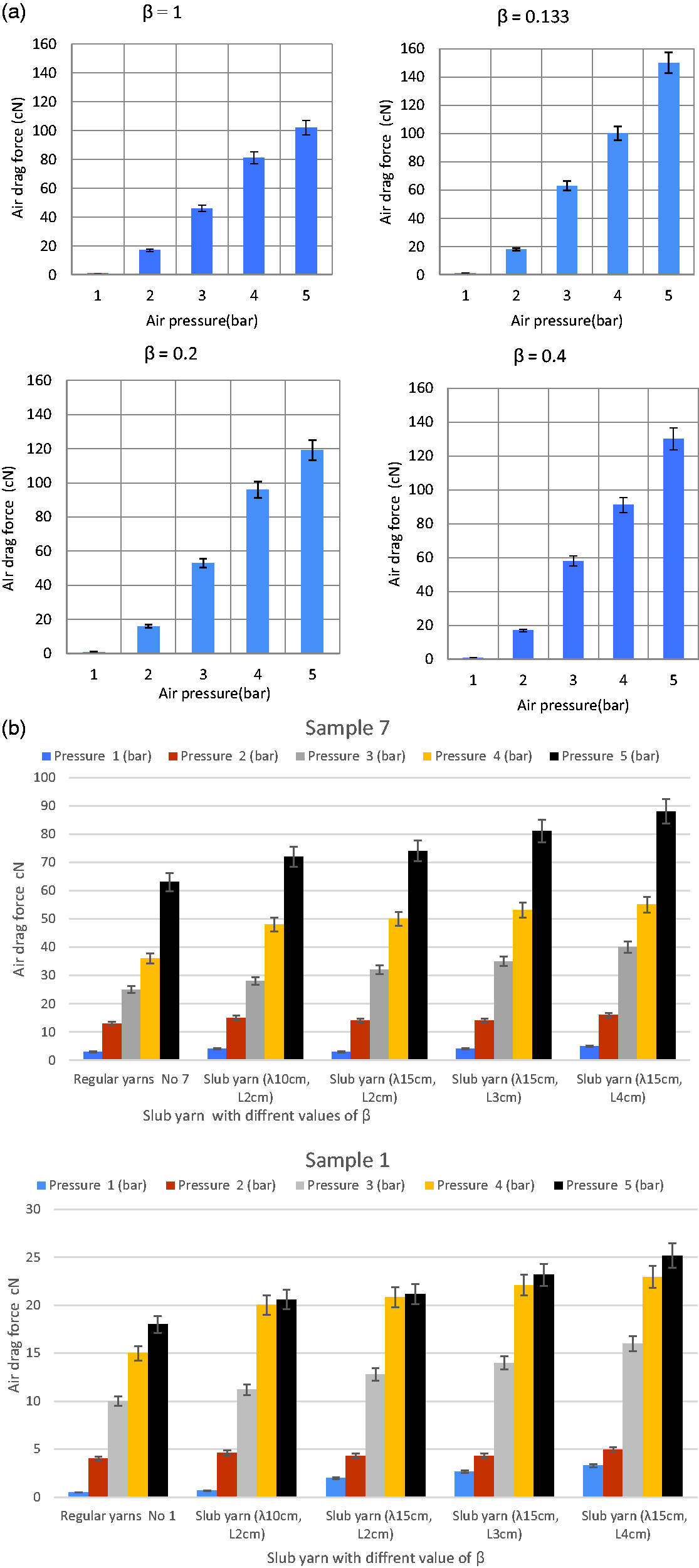
Air drag force of slub yarn with different values of (β) at various air pressures.
The aspect ratio has a significant nonlinear effect at short L/d ratios. The drag force coefficient reduction factor k′ is defined as follows:

The value of k′ was found to be a function of (L/d) as its value approaches the value of one for the value of (L/d) = 100.24,27 Cd∞ is the mean drag coefficient for a cylinder of infinite length (unaffected by aspect ratio). 27
The air drag force will depend on the slub diameter as the value of (β = λ/L) increases. The value of the Reynolds number is expected to be higher. Consequently, slub yarn Cd depends on the value of (β), different shapes of the slub, and the length of the slub.
In this approach, to get the average value of the coefficient Cd, we take the value of the average diameter of the slub portion (dslub) to calculate the value of the air drag force, which is the sum of air drag force on each portion of the slub unit of length (λ). The total air drag force (the driving force for yarn moving in the air jet by the friction between the air and the yarn surface) can be expressed as:


As the air velocity is different in each cross-section, the value of the air drag force will also differ. As explained by many researchers, the air drag force on the bodies of different diameters and configurations is a function of many factors, such as yarn shape, surface roughness, the relative velocity between air and the moving yarn, fluid density and fluid viscosity. Moreover, the coefficient of air drag varies along the yarn length. It is a function of relative velocity, flow direction, positioning of the object, object configuration (shape and size), fluid density, fluid viscosity, and roughness of the surface of the bodies. The results show that most of the yarn properties affect yarn insertion behavior.28–31
Assuming the yarn has a circular cross-section, the Reynolds number can be computed by equation (13):

The speed of the yarn during its weft insertion is small relative to the air velocity at different sections.35,36
The measurement of air drag force for slub yarn
The increase in the value of β means an increase in the average yarn diameter at the slub zone, equation (8), consequently, the air drag force increases too, as shown in Figure 9, which indicates that the value of β affects the air stream profile. The presence of the slub, the high diameter portion, is expected to reduce the air drag force on the lower diameter portion depending on the ratio of the thick slub diameter to the basic yarn diameter. 24
The value of the coefficient of air drag was found to be dependent on the air pressure and the value of β. Figure 11 shows the change in the value of Cd for different values of air pressure p and β. Generally, the increase of Re reduces the value of the coefficient of air drag. The value of Cd for slub yarns is less than that for regular yarns. 24

Air-drag coefficient Cd versus Reynolds number at different air pressure and β.
An empirical equation to calculate the coefficient of Cdi of slub yarn is given by:

The value of Ks depends on the material type and the yarn structure and has an average value of 2.645 for the tested yarns. The calculated results of the empirical equation of air drag force were compared with the measured results. The relation is plotted in Figure 12, which indicates a high correlation between the calculated and measured values of the air drag force. The analysis of variance (ANOVA) analysis indicates that there is a significant difference between the groups of yarns with a different value of (β).

Calculated air drag force versus measured air drag force for slub yarns with different parameters.
On an air-jet loom, cotton slub yarn was used as a weft. The structure of the slub yarn was found to be unaffected by the weft insertion on the air-jet loom as shown in Figure 13, this might be due to the low value of air pressure used, 3 bar. The fabric, woven on the air-jet loom, in Figure 14, shows that the slub weft yarns are firmly enclosed by the warp yarns.

Slub yarn shape before insertion on the air-jet loom and after.
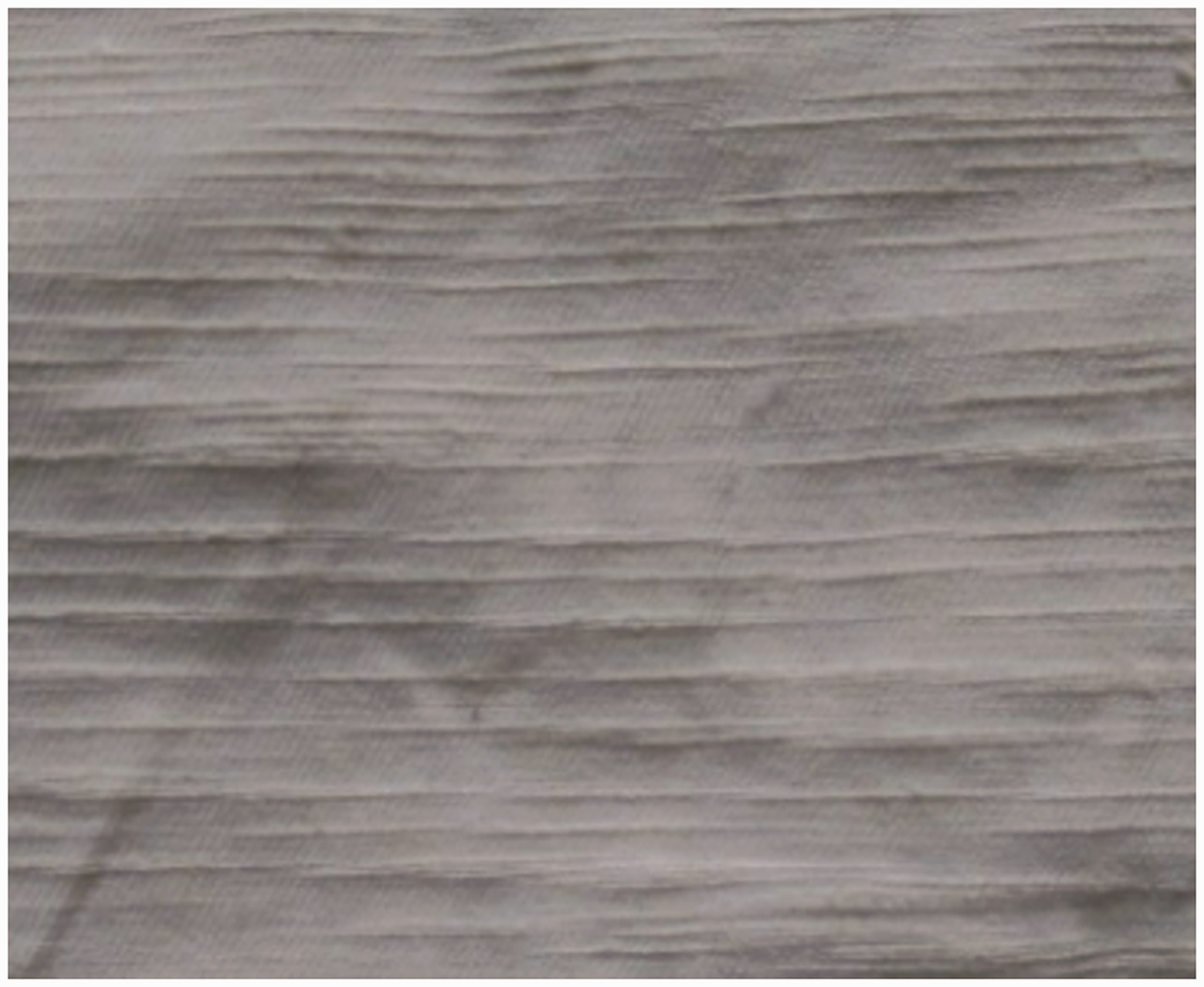
Fabric, woven on an air-jet loom using a slub yarn.
Conclusions
Weft insertion through an air stream is a complex and complicated process especially when slub yarn is used. With the results of experimental and theoretical calculations, the following conclusions can be drawn:
A procedure has been developed to allow the calculation of the weft tension during the insertion process on an air-jet weaving machine. The calculation method allows investigating the effect of the yarn diameter variation, such as in the case of slub yarns, on the total air drag force. The air drag force value depends on the value of Reynolds number, which has a variable value along the yarn length. For normally spun yarns, the air frictional coefficient is found to be Cdi = Kcd p0.4/Rei0.59. The constant K
cd
depends on the fiber type and yarn structure. For slub yarns, the value of air frictional coefficient depends on the slub dimension and the average slub diameter ds. The empirical equation to calculate the coefficient of Cd is given by Cdi = Ks p0.4 β−0.2/Rei0.59. The value of K
s
depends on the type of the material and the yarn structure and is equal to 2.645 for the measured yarns. The value of Cd for slub yarns is less than that of regular yarn. The value of the air drag force increases as the slub ratio β rises. The close comparability and consistency of the experimental and theoretical values endorsed the accuracy of the method developed. The suggested approach takes into account factors concerning the slub yarn geometry that has not been investigated previously.
Footnotes
Declaration of conflicting interests
The author(s) declared no potential conflicts of interest with respect to the research, authorship, and/or publication of this article.
Funding
The author(s) received no financial support for the research, authorship, and/or publication of this article.
