



Abstract
The yarn weave architectures highly influence the mechanical response of woven fabrics. To provide an accurate prediction of the mechanical behaviors of woven fabrics under tension, a mesoscale model is developed. The model takes into account yarn properties, yarn weaving pattern, and interactions between yarns. The yarn properties such as tensile modulus and yarn strength of yarns are considered as random variables. Each yarn in fabric is modeled as a Timoshenko beam with a weaving shape modeled by a parabolic function. The yarn shape evolution and mechanical response of undulated yarn under tension are computed based on Castigliano’s second theorem. The damage initiation and propagation of a yarn in fabric is introduced through a damage variable. The model is demonstrated on woven jute fabrics. Analytical and numerical analyses are carried out and show good prediction on the macroscopic tensile response of woven jute fabric. The model provides a quantitative understanding between yarn geometrical parameters and the expected material response, and makes it helpful for designing woven structural composites with high performance.
Woven fabrics are widely used as reinforcements in composite materials in aerospace, military and automobile fields. As the application of woven fabric for technical fields steadily increases, characterizing the relationship between the woven structure of fabrics and macroscale mechanical response is essential for designing and manufacturing cost-effective fabric reinforced composite structures. However, the multiscale nature and complex internal architectures of fabrics make the design of woven fabric reinforced composites a challenging task. 1
Modeling methods of woven fabrics can be categorized with different scales: (a) microscale; (b) mesoscale; (c) macroscale. Microscale models characterize fabric behaviors at the scale of fibers or filaments. 2 Mesoscale models take into account yarn weave architectures and yarn geometrical factors, such as yarn cross-sectional area, wavelength and amplitude of undulated yarn centerline.3,4 Macroscale models consider that fabrics are uniform and continuous at the macro scale.5–7 Among them, mesoscopic yarn modeling is a more direct way to study yarn weaving structure and analyze the deformation mechanism of fabrics at yarn scale.
Among many applications, mesoscale models are used to predict the mechanical response of woven fabric by considering the yarn behavior,8,9 quantify homogenized material properties for use in continuum models, 10 and can help design woven structure to obtain a wide range of mechanical properties based on the application needs. 2 The mesoscale model can determine the internal yarn structure which conditions the permeability of the fibrous reinforcement during forming, 11 making it possible to simulate the injection process of textile composites.
When fabrics are subjected to uniaxial tensile loads, yarns in fabric undergo a nonlinear response due to yarn bending and interaction between yarns at crossovers. The deformation of fabrics is mainly contributed by yarn extension, yarn bending and compression between weft and warp yarns at the crossover. 12 Lomov and Verpoest 13 divided yarn strain energy into tension and bending energy, and used the principle of minimum strain energy to determine weaving structure parameters, namely wavelength and amplitude. Yang and Zeng 14 proposed a uniaxial tensile model for dry woven fabrics based on the woven structure of fabric yarns. The model takes into account yarn tension, yarn bending and compression of two yarn families at the crossovers. The yarn shape evolution was determined by minimizing the total energy of fabric under stretching deformation. Xiong et al. 15 used stiffness transformation matrix and orientation averaging method to calculate the stiffness matrix of flax fabric with a balanced plain weave structure. Marino and Wriggers 16 proposed a Timoshenko beam model coupling geometric nonlinearities related to fiber planar structure based on the principle of virtual works. Faccio and Gay Neto 8 proposed a geometrically exact beam model with a master-master contact approach to establish a mechanical representation of woven fabrics. Bai et al. 3 idealized orthogonal yarns as curved beams and used the minimum total complementary potential energy principle to predict biaxial tensile strengths.
For the convenience of calculation, the weaving structure is idealized as simple geometrical forms. Many different forms of weaving structure have been put forward. Udhayaraman and Mulay 17 computed the averaged compliance matrix considering undulation configuration of yarns with a sinusoidal undulation approach. Stig and Hallström 18 developed a zig-zag model to explore the influence of yarn curves on the longitudinal stiffness by using linear elastic rods and springs. Xiong et al. 15 divided yarn shape function into an arc in the yarn interaction part and a straight line in the noncontact part. Chaouachi et al. 10 expressed the vertical deflection of yarn in a Fourier series with coefficients depending on force applied on yarns.
The difficulty in mesoscopic yarn modeling is that the yarn woven structure changes during fabric elongation. To obtain the yarn structure evolution, the principle of minimum strain energy was often used to determine the variation of wavelength and amplitude in each iteration step. This complicates the calculation. To circumvent this difficulty, yarns can be modeled as undulated beams because their scale in the length direction is significantly larger than that in the other two directions. The beam shape evolution can be easily calculated from deformation mechanisms and static equilibrium of beams. Meanwhile different yarn structures can be conveniently incorporated in the model by introducing different beam shape functions.
In this paper, a mesoscale tensile model for woven fabric is proposed based on beam theory. The proposed model is expected to characterize the influence of yarn weaving structure on the tensile response of woven fabrics. The undulated yarns in a fabric are modeled as Timoshenko beams subjected to uniaxial traction and contact forces exerted by transverse yarns. Castigliano’s second theorem is utilized to calculate the evolution of yarn shape/path. The maximum stress failure criterion is used to establish damage onset by introducing a random yarn strength. A damage variable is introduced to characterize the progressive failure behavior of woven fabric. The proposed model is implemented in analytical and numerical analyses.
The remainder of the paper is organized as follows. In the Model development section, the analytical tensile model for woven fabrics based on Timoshenko beam theory is proposed. In the section on the Specific application on woven jute fabric, the model is demonstrated on woven jute fabrics. Model mechanical parameters and geometric parameters are determined from experiments on woven jute fabrics. In the Model validation and discussion section, the proposed model is applied to predict the uniaxial tension of woven jute fabric through analytical and numerical analyses. The final section gives the conclusions.
Model development
Beam model
Plain woven fabric is interlaced with warp and weft yarns, resulting in a periodic weaving pattern. The proposed model is based on the analysis of a unit cell of woven fabric shown in Figure 1.

Representative unit cell of balanced plain-woven fabrics.
The unit cell is made of two warp yarns and two weft yarns. Each yarn is modeled as an undulated Timoshenko beam subjected to uniaxial traction and contact forces exerted by transverse yarns, as shown in Figure 2.
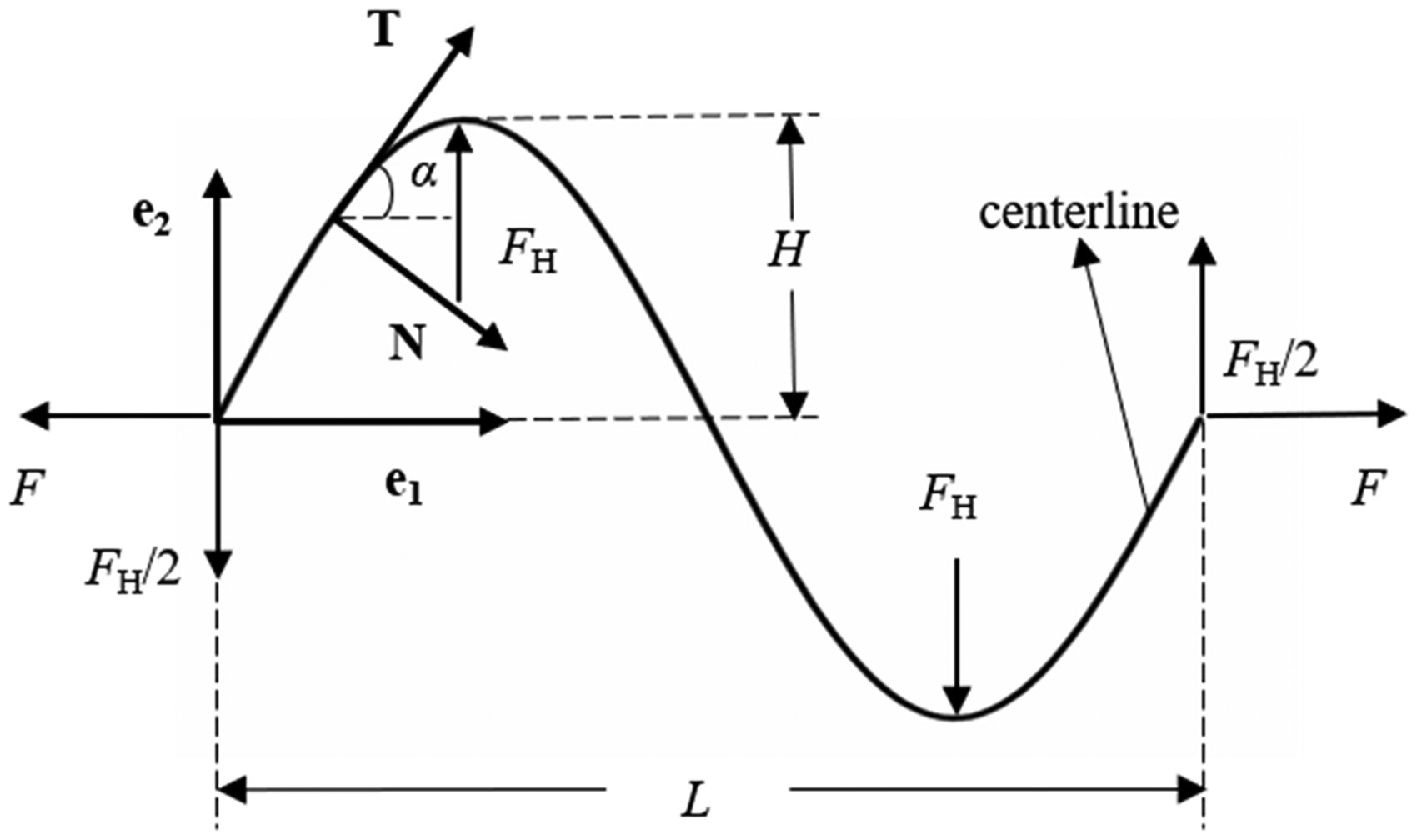
The undulated beam under uniaxial traction F.
The beam model is based on the following assumptions: (a) the yarn cross-section is planar, and symmetric with respect to beam plane; 16 (b) the inter-yarn friction can be neglected in the tensile response of fabrics; (c) the longitudinal yarn carries all of the tensile load; (d) the weft and warp yarns are in perfect contact without slippage.
As shown in Figure 2, (
According to Timoshenko beam theory,
16
the beam centerline is parameterized by a local curvilinear coordinate. An orthonormal basis {

The beam infinitesimal strain is defined as d

Figure 3 shows three configurations of a stretched yarn in the unit cell. In the initial configuration, the yarn is unloaded and has initial weave architecture. The yarn has initial wavelength L0 and amplitude H0. In the intermediate configuration, the yarn is under uniaxial elongation u. Strain along the loading direction can be measured as λ = L/L0. The tensile force due to the applied displacement is expressed as F at the beam end. During the elongation of yarn, the shape function of yarn centerline f(x) changes resulting in a decrease in yarn amplitude and an increase in wavelength. Meanwhile, the yarn is resisted by transverse yarns. The resistance forces F H are at position x = L/4 and x = 3L/4. In the current configuration, an infinitesimal displacement increment Δu is applied. The tensile force increases to F + ΔF. The change in amplitude is ΔH and the resistance force increases to FH + ΔFH.
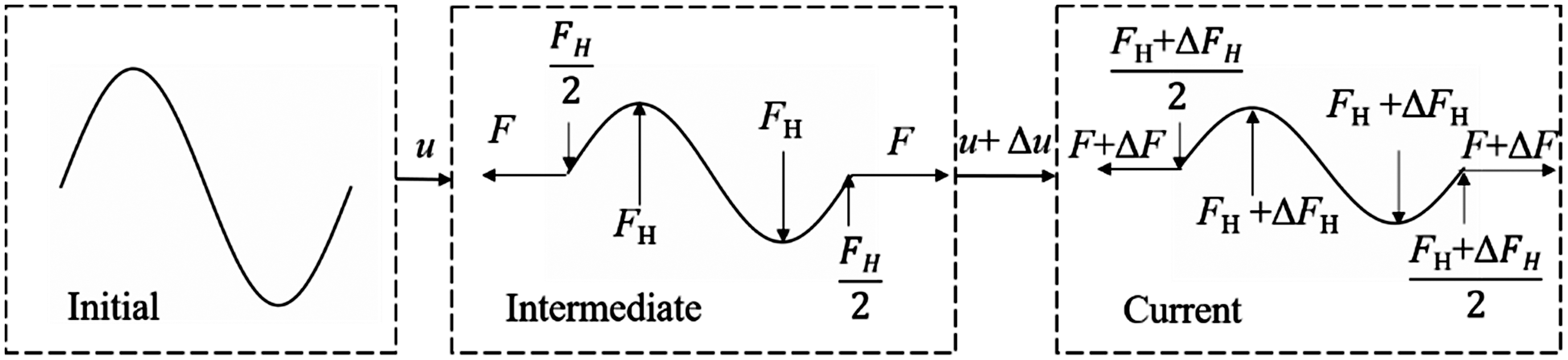
Initial, intermediate and current configuration of a stretched yarn.
The total internal energy Uy* for the yarn from intermediate configuration to current configuration in the Frenet frame is:

The axial force N, shear force Q and bending moment M are expressed as:




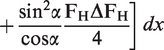

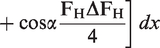



Based on Castigliano’s second theorem, the first partial derivative of the strain energy in a structure with respect to the force applied at any point is equal to the deflection at the point of applied force in the direction of its line of action.
19
So the displacement increment Δu and amplitude increment ΔH in the current configuration are:


The geometric factors GF, GH, GHH depend on the shape function f(x) and are introduced as:
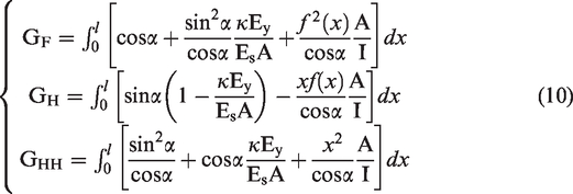

The variation of amplitude with wavelength reveals the evolution of beam shape, which is obtained from equations (9) and (10):

Damage initiation and propagation
Yarns in a fabric are modeled as Timoshenko beams and their tensile force can be calculated from equation (11) through the iteration method. We assume that when the stress of a yarn reaches yarn strength σy, the yarn is broken and stress drops rapidly. To reflect the damage mechanisms of yarns in a fabric, a damage variable d is introduced as:

The damage variable d is the ratio of drop stress over damage initiation stress. The damage variable d = 0 represents the undamaged state of the yarn, while d = 1 represents complete damage. The parameter df controls the speed of the damage evolution.
In woven fabrics, the broken yarn can still bear a small tensile load due to the friction between the broken yarn and transverse yarns. The parameter kd is introduced to determine the stress remaining in the yarn after complete failure.
So the yarn stress after initial damage can be defined as:

Woven fabric model
It is assumed from the mixing theory
20
that under uniaxial tension, the strain of each yarn


The woven fabric model is suitable for fabrics with a balanced plain-woven fabric structure shown in Figure 1. In addition, for natural fiber yarn fabrics, due to heterogeneities of natural fibers and fiber twisting, high dispersions of yarn mechanical properties including yarn tensile modulus E
y
and yarn strength σy exist. They can be characterized by certain probability distribution functions.
21
The mesoscale woven fabric model combines the mixing theory
20
and probability distribution of material parameters. The model parameter identification procedure is as follows:
Measure the geometry shape of yarn to obtain cross-sectional area A, second moment of area I and shear correction factor κ. Apply statistical analysis to obtain probability distributions of yarn tensile modulus E
y
and yarn strength σy. Measure the woven structure of fabric to obtain the initial wavelength L0 and amplitude H0. Determine the shape function f(x) and incorporate it into the model to calculate the geometric factors GF, GH, GHH. Fit the compressive curves of woven fabrics to obtain the format of resistance force function Determine the damage parameters df and kd from the tensile tests of a yarn in woven fabric.
Specific application on woven jute fabric
The tensile model based on the mesoscopic scale is demonstrated on a woven jute fabric, as shown in Figure 4. Model parameters are determined by the guideline in the Woven fabric model section.
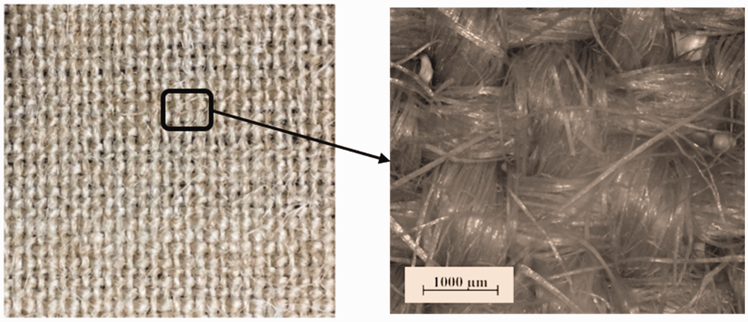
Woven jute fabric.
Yarn geometric parameters
Jute yarns were detached from balanced woven jute fabrics. Each yarn was wound by hundreds of jute fibers. The yarn cross-section is assumed to be oval. The geometric parameters of jute yarns were measured and listed in Table 1. The lengths of the major axis a1 and the minor axis a2 are 1.0 mm. and 0.2 mm, respectively. The cross-section area of jute yarn is
Geometric parameters of jute yarns

Yarn mechanical parameters
The heterogeneities of natural fibers24,25 result in significant dispersion in yarn mechanical properties, such as tensile strength and elastic modulus.26–28 The statistical distributions on tensile modulus E y and yarn strength σy of jute yarns are listed in Table 2. 21 The shear modulus E s of jute yarns is assumed to be 30 MPa.29,30
Statistical distributions of the properties of jute yarns 21

Shape function and weaving parameters
The parabolic function is selected as the shape function of the jute yarn in the unit cell:
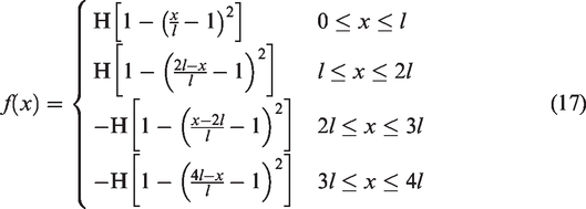

The fundamental parameters of yarn shape are the initial wavelength L 0 and amplitude H 0 . The number of periods Np in 100 mm long fabric is counted and the initial wavelength L0 can be calculated by L0 = 100 mm/Np. Then, yarns detached from 100 mm long fabric is straightened and the length Lp. is measured. The arc length larc can be obtained from larc = Lp/Np. Then the beam initial amplitude H0 can be obtained from equation (18). The initial wavelength L 0 and amplitude H0 of the woven jute fabric are thus obtained as 2.649 mm and 0.1 mm, respectively.
So the geometric factors GF, GH, GHH in equation (10) can be solved as:
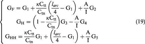
The factors G1, G2, G3, G4 and G5 are:
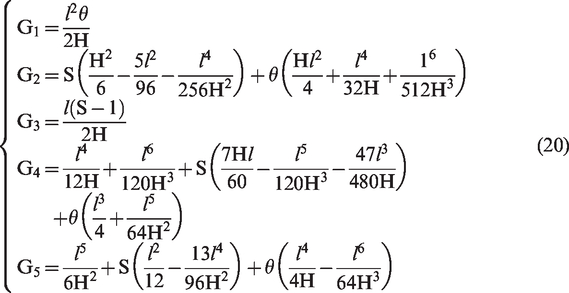
Yarn structure is sensitive to the nonlinear mechanical response of fabrics. 31 It requires the model to be able to characterize different types of yarn fluctuations and calculate yarn curve change in the fabric. Different yarn curves can be conveniently incorporated in the model by introducing geometric factors GF, GH, GHH.
Resistance force at the crossover of yarns
The relationship between resistance force and yarn amplitude is estimated from the compressive response of the woven fabric. The fabric specimen size is 10 mm × 10 mm × 1 mm. Compression tests were implemented at a speed of 2 mm/min at room temperature. The testing curve is presented in Figure 5. The resistance force in Figure 5 is determined by the compression force of woven fabric divided by the number of crossovers in the fabric and can be expressed as:

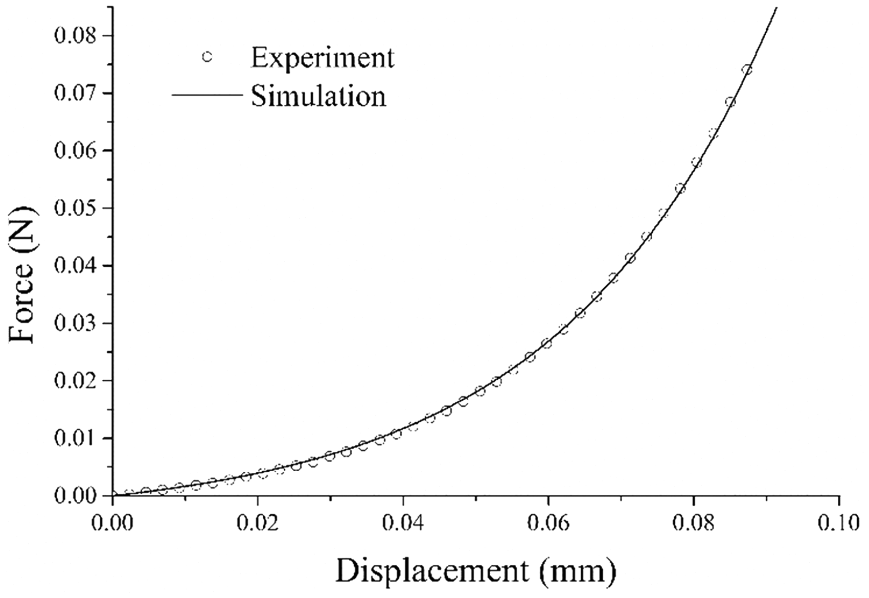
The compression test of woven fabric.
Damage parameters
To determine the damage parameters, tensile tests of a yarn in woven jute fabrics were carried out at a speed of 2 mm/min, as shown in Figure 6. The specimens are 100 mm long and contain 21 yarns. The yarn in the middle of the specimen is stretched, and the test result is shown in Figure 7.

Schematic view of the tensile test of a yarn in fabric.

The tensile curve of a yarn in woven jute fabric.
When the yarn reaches the damage initiation, yarn breakage appears, resulting in a rapid drop in force. By fitting the damage propagation region of the tensile curve, the damage parameters df. and kd were determined as 10.0 and 0.7, respectively. The yarn residual stress after yarn complete failure is 30% of yarn strength.
Model validation and discussion
Uniaxial tensile prediction of woven jute fabric
Assuming that the woven fabric has n yarns in the stretching direction. The tensile model with progressive damage is implemented in MATLAB software. (a) Each yarn is assigned random tensile modulus Ey(i) and yarn strength σ y (i) according to probability distributions in Table 2. (b) Calculate the force increment and amplitude increment in the current configuration. Then the tensile force and yarn shape of the current step are updated through the iterative method. (c) If the yarn stress is greater than the yarn strength, the yarn is broken and yarn stress can be calculated from equation (14). (d) Calculate the total force of the woven fabric from equation (16).
Uniaxial tensile tests on woven fabric specimen were carried out at a speed of 2 mm/min. Each specimen contained 20 yarns and the gauge length was 100 mm. The tensile tests were repeated with four samples. When fabric elongation exceeds 2 mm, tensile curves enter the linear elastic region whose slope is used to calculate the tensile modulus of woven fabric. The mean of fabric tensile modulus was 6024.0 MPa, the standard deviation was 301.1 MPa. The coefficient of variation was 0.049. Compared with yarn tensile modulus, the dispersion of fabric tensile modulus is small and ignorable.
Figure 8 shows the simulation and experimental results of tensile curves of woven fabric. Results show that the model can well predict the nonlinear tensile response and progressive failure process of woven jute fabrics.
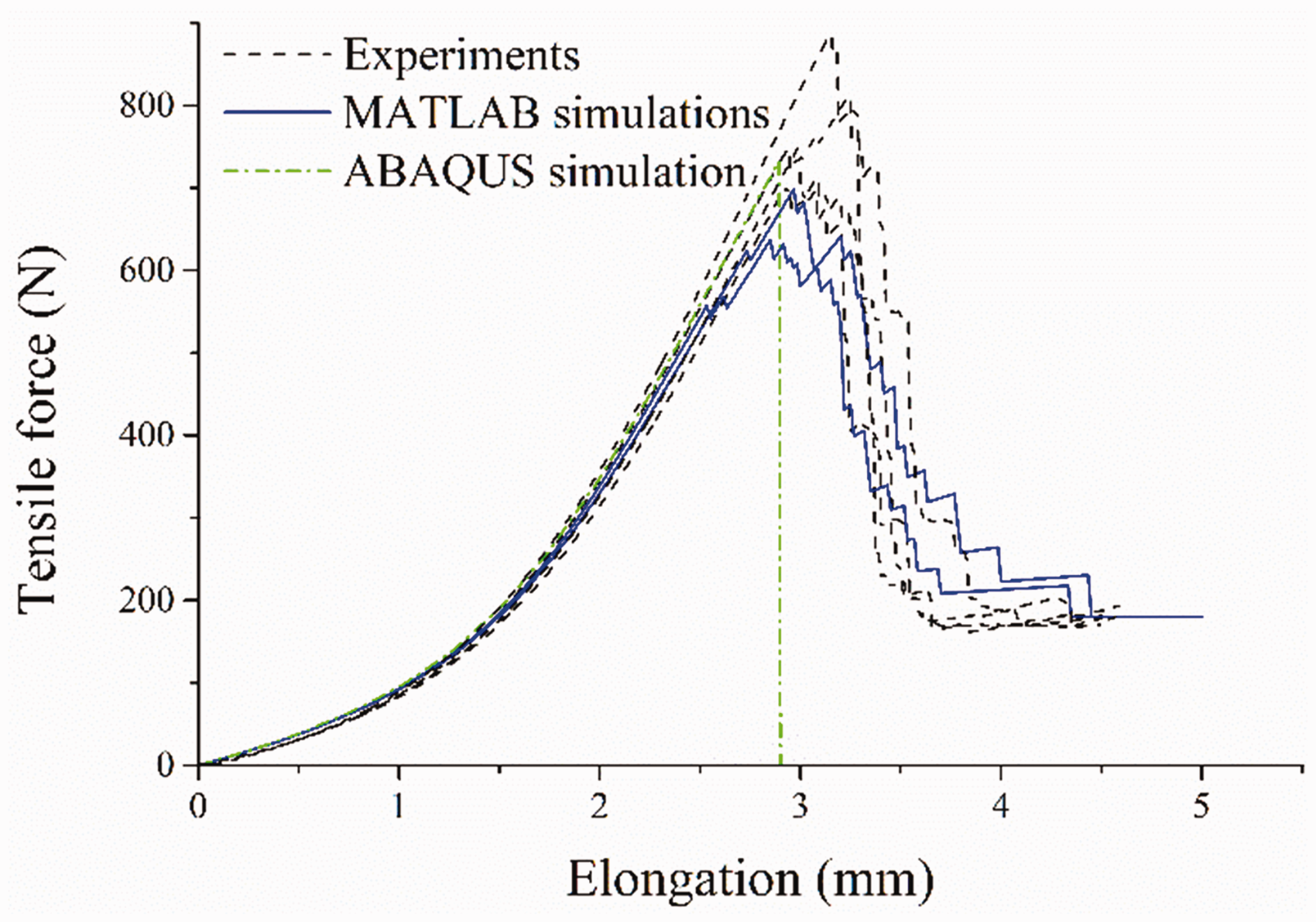
Uniaxial tensile tests of woven jute fabric.
The amplitude variation is defined as Avar = H/H0 to evaluate yarn shape evolution. 16 The amplitude variation and yarn elongation along the arc length direction of a yarn in the fabric are shown in Figure 9. The strong nonlinearity in the initial tensile stage of woven fabric is mainly due to the variation of yarn weaving shape. As yarns are straightened and yarn amplitude decreases, the yarn stiffness is gradually activated leading to a significant increase in fabric tensile modulus.
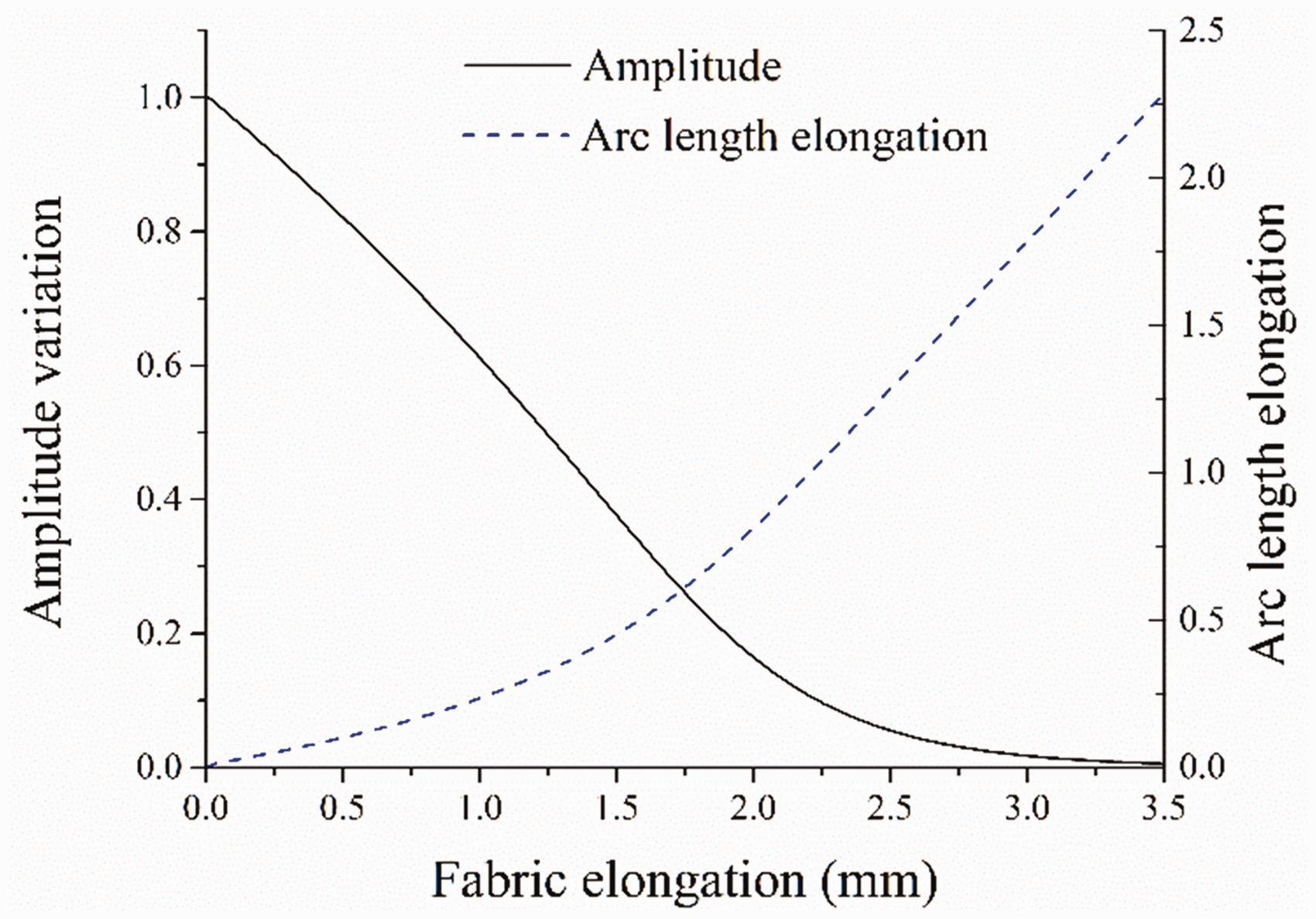
The variation of amplitude and arc length elongation with fabric elongation.
Numerical implementation of the model
The model was implemented in ABAQUS through a user subroutine VUMAT. To be applied in finite element analysis, the mesostructural behavior has to be related to the macroscopic deformation. Through the homogenization method, the unit cell can be represented by two S4R shell elements with a dimension of 2.65 mm × 1.325 mm × 1 mm, as shown in Figure 10. The combination of the analytical model and continuum elements makes it possible for the explicit modeling of the geometric structure of the textile with acceptable computational cost. 10
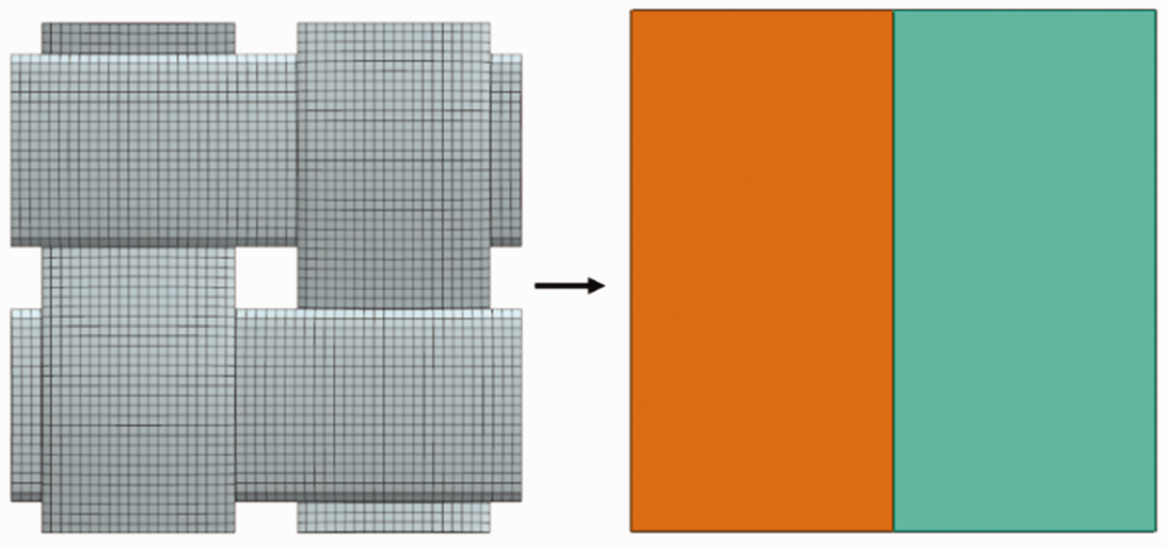
The elements of a unit cell.
The stretches along yarns in the current configuration can be represented by the following invariants:


Then the tensile force can be calculated from equation (11) through the iterative method. The cross-sectional area of an element in unit cell A
e
is 1.325 × 1 mm2. The tensile stress of the unit cell can be expressed as
To simulate uniaxial tension of a woven jute fabric containing 20 yarns, the specimen with a dimension of 100.7 mm × 26.5 mm × 1 mm was meshed with S4R type shell elements, as shown in Figure 11(a). Each column of the elements is a yarn and was assigned with the same material properties. Different columns were given random tensile modulus and yarn strength following the probability distributions in Table 2.

(a) The finite element model of the woven jute fabric; (b) the tensile simulation result of the woven jute fabric with random material parameters; (c) the woven jute fabric after tensile test and (d) the tensile simulation result of the woven jute fabric with the same material parameters.
Finite element model (FEM) analysis of the tensile process of woven fabric was established in ABAQUS/Explicit. In the postprocessing of ABAQUS, elements with damage parameter d exceeding 0 indicate that yarns are damaged. So these elements were removed from the model to show the broken fabric. Figure 11(b) shows the broken fabric at the end of the simulation. Figure 11(c) shows the broken fabric at the end of the tensile test. The removed elements in the model are distributed similarly to the damaged parts of the woven fabric specimen. Then all elements were assigned the same material properties; the simulation result is shown in Figure 11(d). The simulation result shows that all yarns break simultaneously at the lower end and the stress distribution is relatively uniform. It is different from the tensile test results in Figure 11(c). So the model with random material parameters can well predict the progressive failure of woven jute fabric and reflect the damage mechanism of woven jute fabric.
The simulated tensile curves are shown in Figure 8. In FEM analysis, each element is influenced by surrounding elements. When an element is damaged, the entire model is quickly destroyed. So the tensile curve of the finite element simulation breaks earlier compared to the MATLAB simulation.
The mesoscale tensile model can be applied to predict the macroscale tensile response of woven fabrics. However, due to ignoring the interyarn friction, the model has limitations in predicting shearing behavior. The interyarn friction at the crossover of yarns and the enhanced resistance of yarns caused by the change of angle between two directions of yarns will be considered in our further study to characterize the in-plane shear deformation of fabric.
Conclusions
A mesoscopic model of woven fabrics was proposed based on Timoshenko beam theory to model the tensile response of woven fabric. The undulated yarn in fabric was modeled as a Timoshenko beam. Castigliano’s second theorem was used to compute yarn weaving shape evolution. The model characterizes the relationship between the woven structure of fabrics and the macroscale mechanical response of woven fabrics. Due to the introduction of yarn shape function and geometric parameters, different yarn weaving structure can be conveniently incorporated in the model.
The proposed model was implemented in analytical and numerical analyses. The model can well predict the macroscopic mechanical response of woven fabric. Meanwhile, the damage initiation and development in woven fabrics can be well simulated by introducing random yarn tensile strength and damage variables. The tensile simulation shows good agreement with the experimental result. Because of some simplifications of the model, the contact between yarns was represented using concentrated force and the change of yarn cross-sectional shape was ignored. The yarn-to-yarn contact behavior and relative yarn rotation will be considered in our future work.
Footnotes
Acknowledgement
Support from the National Natural Science Foundation, China (U20A20288, 11972225) is gratefully acknowledged.
Declaration of conflicting interests
The author(s) declared no potential conflicts of interest with respect to the research, authorship, and/or publication of this article.
Funding
The author(s) received no financial support for the research, authorship, and/or publication of this article: This research is funded by the National Natural Science Foundation of China (U20A20288, 11972225).
