
Abstract
Stent insertion can serve as an effective therapy method for patients with esophageal stricture but stents with inappropriate mechanical properties lead to restenosis. To prepare a stent matching the esophageal environmental mechanics, both the NiTi spring yarn and polyester multifilament were used to produce seven kinds of stents by braiding technology. The mechanical properties of the stents were tested including compression, flexibility, and antimigration behavior. Results showed that three different parameters including spring consistency with tracks, spring content, and spring pitch altered the effective number of coils and elastic modulus, and affected the compression strength, flexibility and migration resistance of the stent. In particular, the integrated braided stent with full consistency, 12 NiTi spiral yarns, and spring pitch of 1.00 mm had the best mechanical properties among all the prototypes in this research. The compression strength, bending strength, and migration resistance were 1048.75 cN, 46.35 cN, and 3.74 N, respectively. In summary, this research presents a new preparation method for esophageal stent manufacture in the treatment of inoperable esophageal malignancies.
Keywords
Esophageal cancer has been considered one of the most difficult malignancies to cure and with high morbidity and mortality. 1 More than 50% of esophageal cancer patients are clinically diagnosed with advanced esophageal cancer, with the diameter of the stenosis reaching 50%. Stent implantation can effectively open the esophagus and alleviate dysphagia in a short time, hence improving patients’ quality of life by allowing oral drinking and eating as well as swallowing saliva.2–4 However, esophageal stents cause several complications including bleeding, migration, and tumor overgrowth, which is associated with the inappropriate mechanical properties of the stents.2,5,6 Literature about the esophageal stents’ failure analysis indicates that high radial force, poor flexibility, and low frictional force are the main drawbacks in clinical application,2,7 because the esophageal stent is subjected to various mechanical forces in the esophagus environment, including the peristalsis of the swallowing progress during eating and the bending caused by the vicinity of the cardia.8,9 The insufficient compression force of the stent leads to tissue ingrowth and restenosis. In contrast, the excessive compression force of the stent may lead to perforation and bleeding. 10 When the flexibility of the stent is poor, the ends of the stent will occasionally cause fistula or perforation. 11 In addition, there is friction between the surface of the stent and the inner wall of the esophagus after the stent is implanted, when the friction force of the contact is small, the stent migrates into the stomach. When the above situation occurs, it means the stent implantation fails. 12 Therefore, implantation of stents with appropriate mechanical properties prevents the esophageal tissue injury phenomenon. There have appeared several types of research about stent structure design to improve its mechanical properties. Verschuur et al. 13 designed a double-layered stent that effectively reduced the migration probability, but increased the expansion force of the stent, causing the patient to have chest pain. Bi et al. 14 reported that although the segmented stent graft reduced flexibility and avoided the problem of proliferation at both ends of the stent, but the migration rate after stent implantation is as high as 16%. Guo et al. 15 developed a Zn-0.1 Li alloy and evaluated the in vitro performance, the relative faster degradation rate in simulated gastric fluid and weakening of the mechanical strength. To gain a better therapeutic effect, it is of great significance to prepare a stent with suitable radial force, good flexibility, and high resistance to migration.
Overall, currently, clinically used esophageal stents are usually prepared by laser engraving or a braiding technique. 16 Laser-cut stents have a thin ‘wall thickness’ and delivery profile compared to the braided stents, but migration occurs commonly.17,18 Braided technology is a universal process, and the mesh structure produced by braided technology has radial strength, flexibility, and shape recovery.19,20 The in vitro mechanical characterizations are relevant to clinical results. Stents manufactured by braided technology are expected to overcome clinical problems such as restenosis, which results from insufficient mechanics and migration. Adjusting the mechanics of the braided esophageal stents mainly includes two aspects. One is adjusting the radial force through the number and diameter of the metal wires. The other is designing segmental stents to reduce the axial force through structural changes and increase the friction coefficient and contact force of the stent surface.14,21 The design should balance several mechanical properties of the stents to avoid complications.
Our group recently reported an integrated braided structure of the tubular stent, which combined the NiTi supporting part (spring yarn) with the polyester fabric membrane-covered part.22,23 NiTi has superelastic properties and can be crimped into a small delivery diameter then without expanding into the esophagus without plastic deformation. 24 Polyester materials have good biocompatibility and are authorized for clinical use by the US Food and Drug Administration. 25 This special structure could support a narrowed internal cavity and avoid the friction between rigid NiTi spring yarn and flexible polyester fabric. The mechanical behavior of the braided stents is defined mainly by material and structure such as yarn diameter, braiding angle, and other braiding parameters. 26 According to the literature, the elastic modulus of NiTi is 80 GPa while it is 2500 MPa for polyester; metallic material is more rigid than polymer material. Hence, NiTi plays a major role in stent mechanical properties and change parameters have a significance. In addition, the braiding parameters will affect the clinical supporting effect of the esophageal stent with NiTi spring yarn and polyester filament integrated braided structure. This integrated structure is suitable for esophagostenosis, especially in an environment with solid foods. In this study, the stents were braided by two materials, NiTi spring yarn and polyester multifilament. To explore the structure–activity relationship of the stents and optimize it, three key parameters were changed to explore their effects on mechanical properties including the consistency of NiTi yarn rotation direction with braiding track, NiTi yarn content, and spring pitches. Seven kinds of stents were prepared to explore the compression, deployment, flexibility, and antimigration behavior of the stents. Realistic stent loading conditions were investigated for in vitro testing. Hopefully, the quantitative mechanical properties will provide guidelines for esophageal stent implantation.
Materials and methods
Polyethylene terephthalate (PET 1000 D/192 F, Tg = 210°C) multifilament yarns (Kejia Company, Nantong, China) and biomedical grade nitinol (NiTi with a diameter of 0.2 mm) spring yarn (Fujiang Medical Technology Co. Ltd., Zhuhai, China) were selected to fabricate the prototype stent with an outer diameter (∼10 mm). The inner diameter of the mandrel was 9 mm.
Design and fabrication of integrated braided stents
The fabrication of the stent was divided into two parts, in the first section the NiTi spring was prepared. The NiTi spring preparation process is indicated in Figure 1, the NiTi wire was wound and fixed on the screw and heated in a muffle furnace (Company Profile of Nabertherm, Shanghai, China) at 550°C for 10 min. NiTi yarns were available in three types of spring pitches including 1.0 mm, 2.0 mm, and 3.0 mm, each pitch screw contained left (L) and right (R)-handed direction. The second section was the braiding process of the stent. The braiding process is also shown in Figure 1. The braiding machine, designed and fabricated by our laboratory at Donghua University with 48 bobbins, was used to fabricate integrated braided stents. Seven kinds of specimens (three groups) were obtained by changing the consistency of NiTi spring direction and braiding track, NiTi wire content, and spring pitches, the specific parameters of each kind of stents and their names are presented in Table 1 and Figure 2. To discuss the consistency of the yarn and braiding track on the mechanical behavior of the stents, the number of the NiTi yarns is constant. That is 12 yarns evenly distributed in this group stent, while the consistency of NiTi yarn rotation direction and braiding track during the braiding process contained full consistency, half consistency, and no consistency, accordingly named as FC1.0, NC1.0, and HC1.0. Different NiTi wire contents meant all yarn in the stent where NiTi wire (full consistency) was arranged symmetrically with numbers of 8, 12, or 16. In this group, stents were named FC1.0-8, FC1.0, and FC1.0-16. Spring pitches included 1 mm, 2 mm, and 3 mm, according to the single factor experimental protocol, each kind of spring (12 pieces) was braided with polyester (full consistency). In this group, stents were named FC1.0, FC2.0, and FC3.0. The inner diameter of the 9 mm stent was consistent, which was prepared by keeping the cylindrical mold with the same outer diameter. After braiding, all samples were treated under heat setting conditions at 190°C for 7 min in an electro-thermostatic blast oven (Shanghai Yiheng Scientific Instrument Co. Ltd., Shanghai, China).
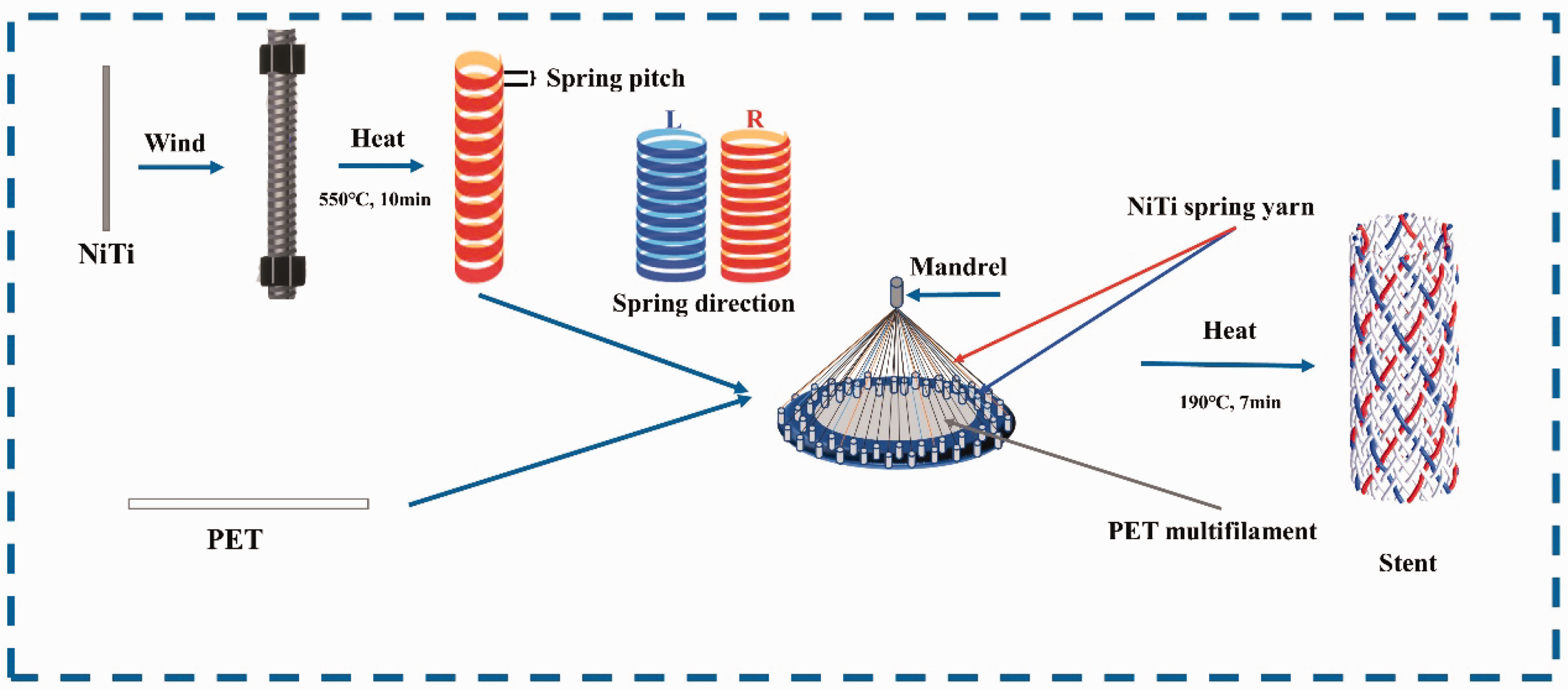
Schematic diagram of wire shaping and braiding process.
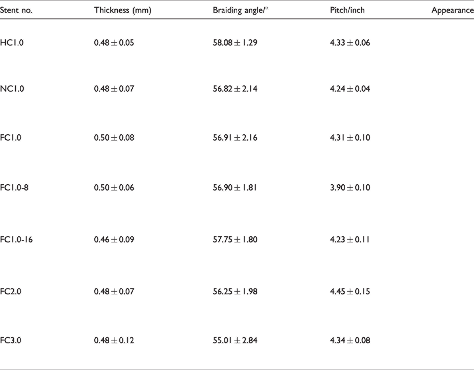
Structural parameters of the prototype stents


Design and parameters of prototype stents. (a) Different consistency stent: FC1.0, HC1.0, and NC1.0; (b) Different content stent: FC1.0-16, FC1.0, and FC1.0-8 and (c) Different pitch stent: FC1.0, FC2.0, and FC3.0.
Testing methods
The environmental parameters were controlled temperature (20 ± 1°C) and relative humidity (65 ± 2%). Mechanical tests of all samples were conducted under the above-mentioned conditions. Five specimens of every kind of sample were tested.
Morphology characterization
The morphology of the stents was investigated by stereomicroscope (PXS8-T; Cewei Photoelectric Technology Co. Ltd., Shanghai, China). The structure parameters containing the braiding angle (the angle between and the axis of stents and the helical yarns) and pitch length (the same yarn in a closed helical along the vertical direction) of integrated braided stents were obtained from the microphotographs. In addition, another structure parameter was thickness (thickest yarn-crossing points) and it was gauged by an electronic vernier caliper (Kinsey Ride, Foshan, China).
Compression testing
The radial compression behavior is a fundamental property of the stent. In this study, transverse compression was used as the measuring method according to ISO 25539-2.22,27 Figure 3(a) shows that the diameter of the presser foot was 15 mm, and its velocity was 40 mm/min (LLY-06D; Laizhou Digital Instrument Co. Ltd., Shandong, China). The size of the stent sample was 10 mm in diameter and 60 mm in length. The stent was compressed down to 50% of the diameter of the stent and kept for 30 s. Then the presser foot was raised to the initial situation for 30 s and lowered down to touch the stent again. After the test was conducted, a compression load–displacement curve was formed (Figure 4). Four parameters characterized the compression performance of the stent. The radial force (F1) was the value at which the stent was compressed to 50%. The chronic outward force (F2) was the value when the unloaded diameter of the stent force reaches 75%. The elastic recovery rate and energy loss rate of the stent were calculated as in the following equations (1) and (2), respectively:
28


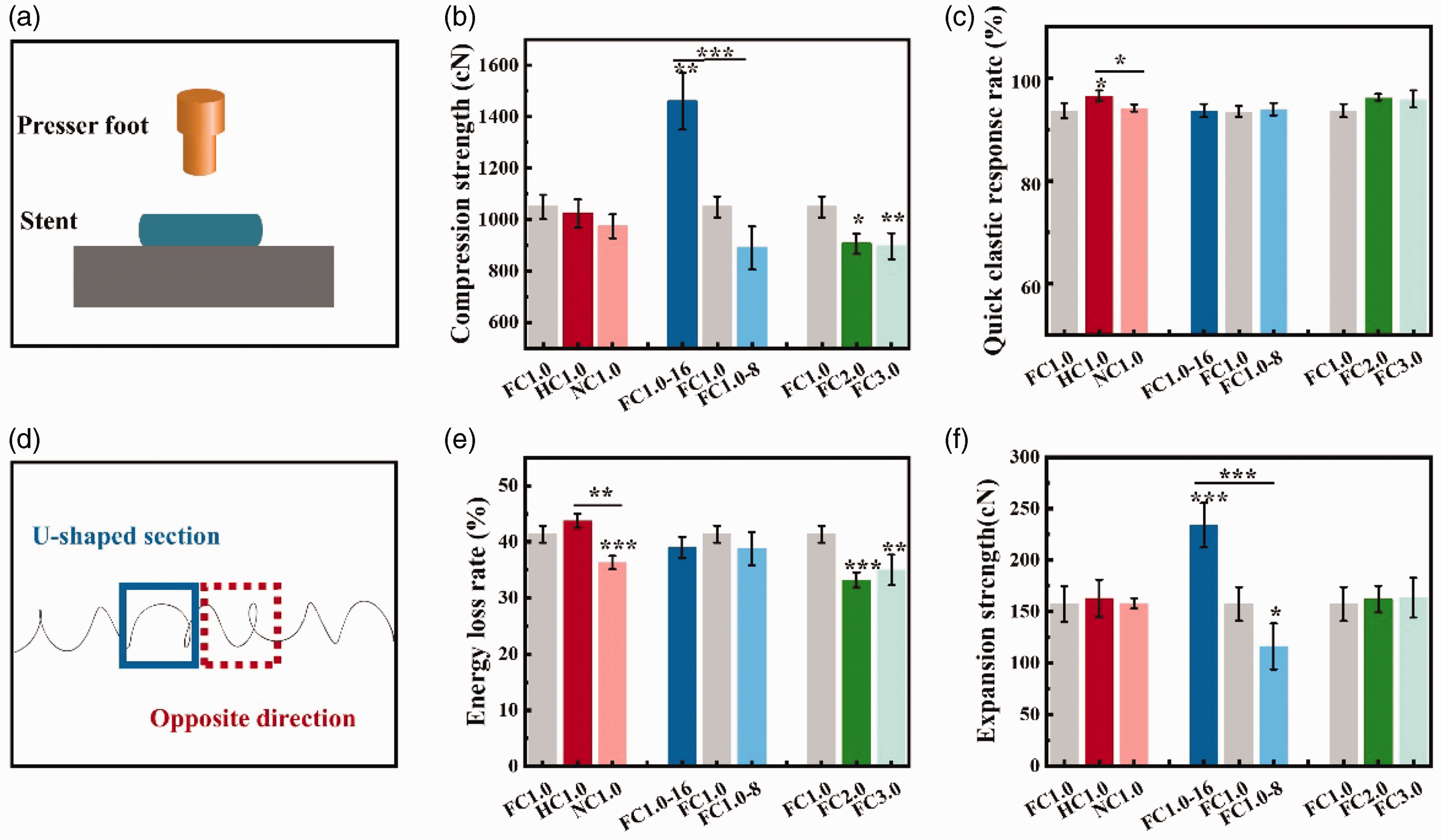
Compression performance characterization. (a) Schematic diagram of the compressed test; (b) Quick elastic rate of the stents; (c) Compression strength of the stents. (d) Braiding error, U-shaped spring and opposite spiral and (e) Compression energy loss rate and (f) Expansion strength of the stents.
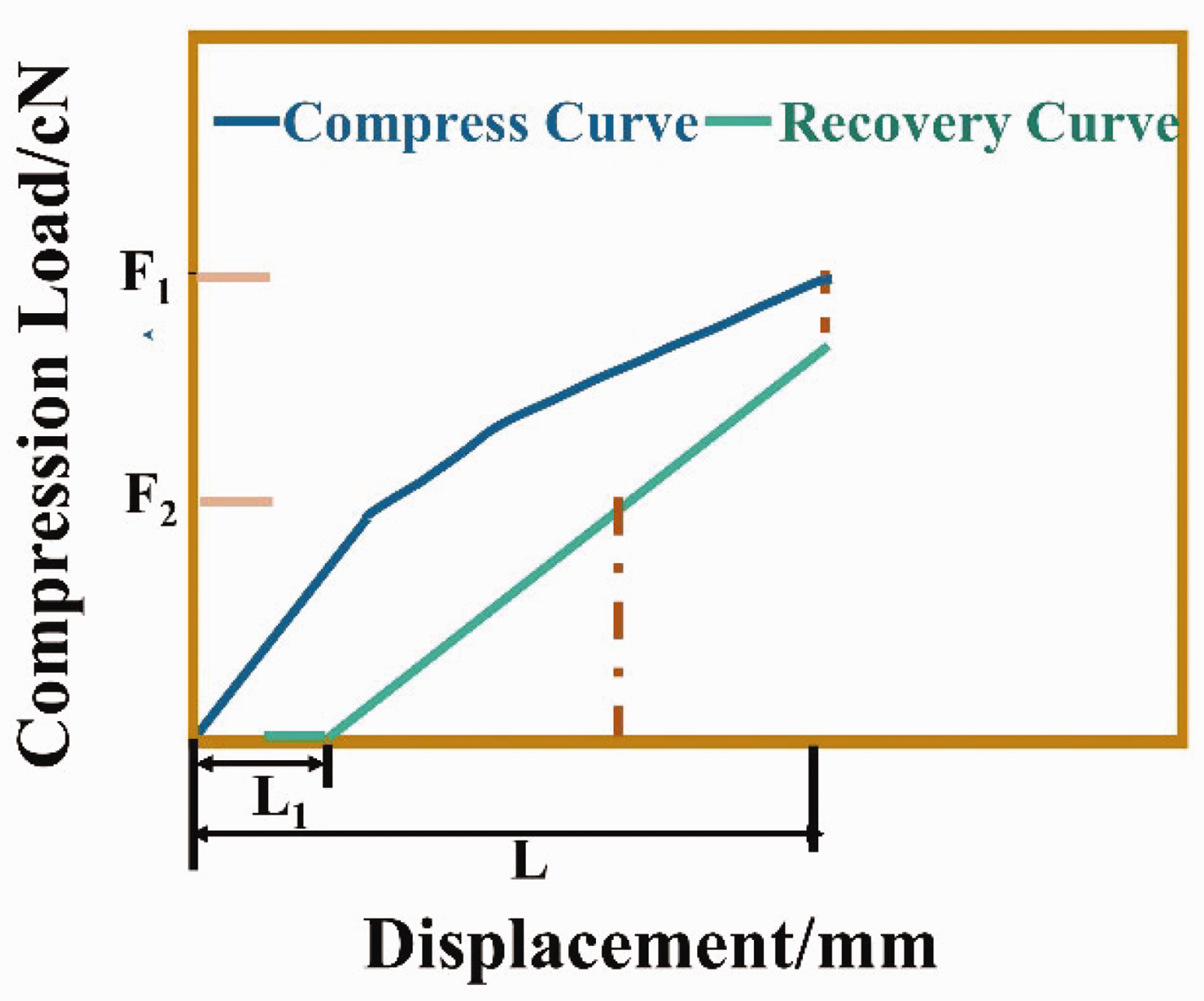
The compression load-displacement curve.
Furthermore, the strength and energy retention rate of the stent under 10 compressions were explored initially to stimulate the peristalsis of the stent during swallowing.
Deployment testing
Clinically, the esophageal stent implantation is through a delivery system, which contains a 18 Fr/6 mm catheter. 29 After 24 h of compression in the catheter, expansion of the esophageal stent should be observed to validate the accuracy and repeatability of the stent after being removed from the catheter. 30 Thus the compression test of the stents was conducted after being removed from the catheter with a 6 mm inner diameter after 24 h (Figure 5(b)) 31 and was named expansion strength. The same test conditions as compression force testing were used. Each stent was compressed one cycle (load–unload). The shrinkage rates after 10 compressions of the stent were characterized. In addition, test parameters including F1 and F2 were shown in the compression test.
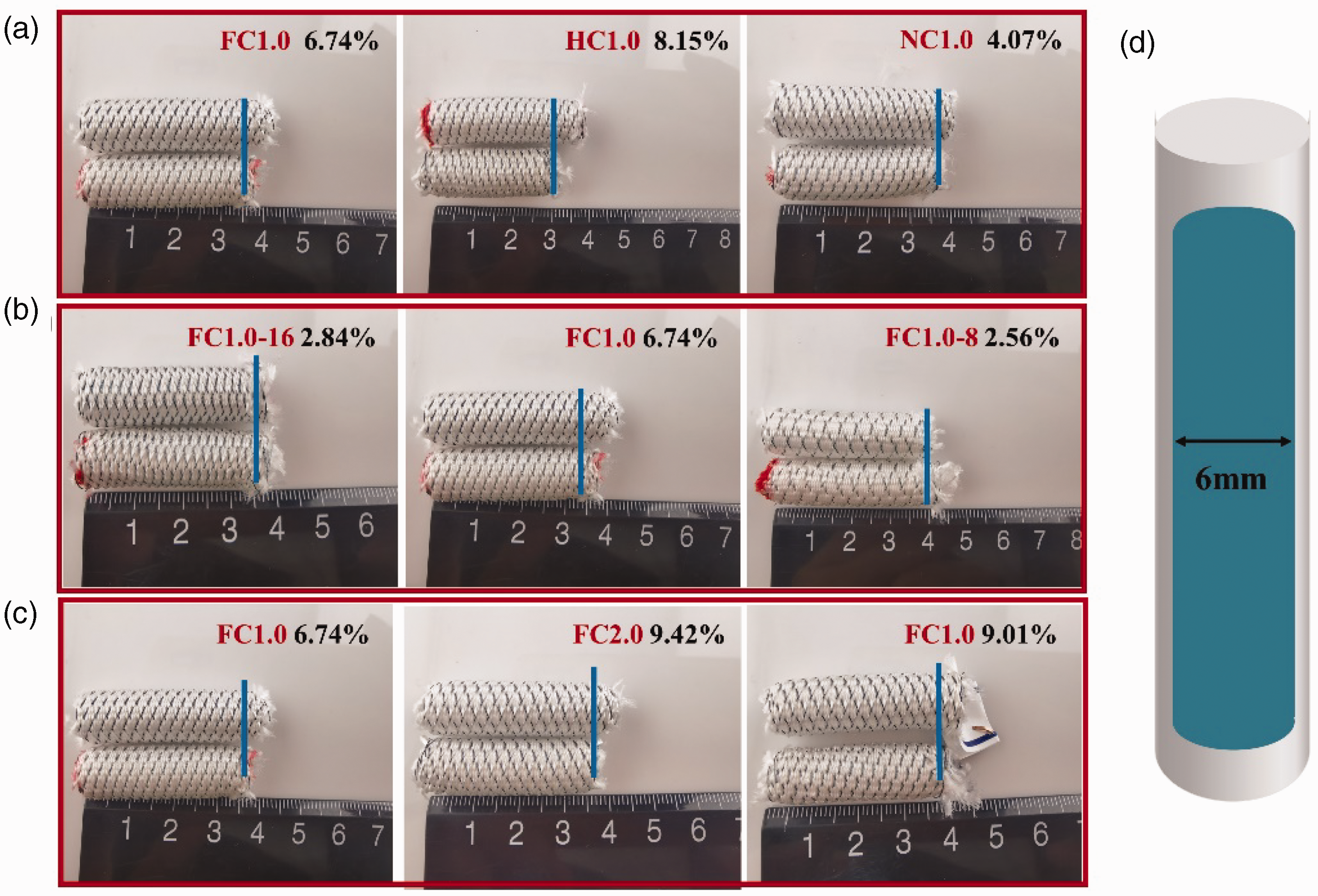
Appearance results of stents after 24 h compression. (a) Axial dimension change of different consistency stent after 24 h compression; (b) Stent compression experiment process during 24 h compression; (c) Axial dimension change of different content stent after 24 h compression and (d) Axial dimension change of different pitch stent after 24 h compression.
Flexibility testing
Flexibility is usually measured as a force to bend the stent. As shown in Figure 6(a), the sample was inserted into a custom-made fixture. The fixed part was designed to simulate the stent fixed in the esophagus, and the free end part of the stent simulated free movement in the stomach.10,12 The diameter of the presser foot of the instrument (modified LLY-06D; Laizhou Digital Instrument Co. Ltd., Shandong, China) was 5 mm, and we placed it 20 mm away from the fixed point of the stent. The experimental apparatus bent the flexible part of the sample to 20° at a speed of 40 mm/min. The selection of this angle simulates the small curvature of the stent along the stomach. The bending force (maximum load value) of the stent after bending was recorded by the sensor.
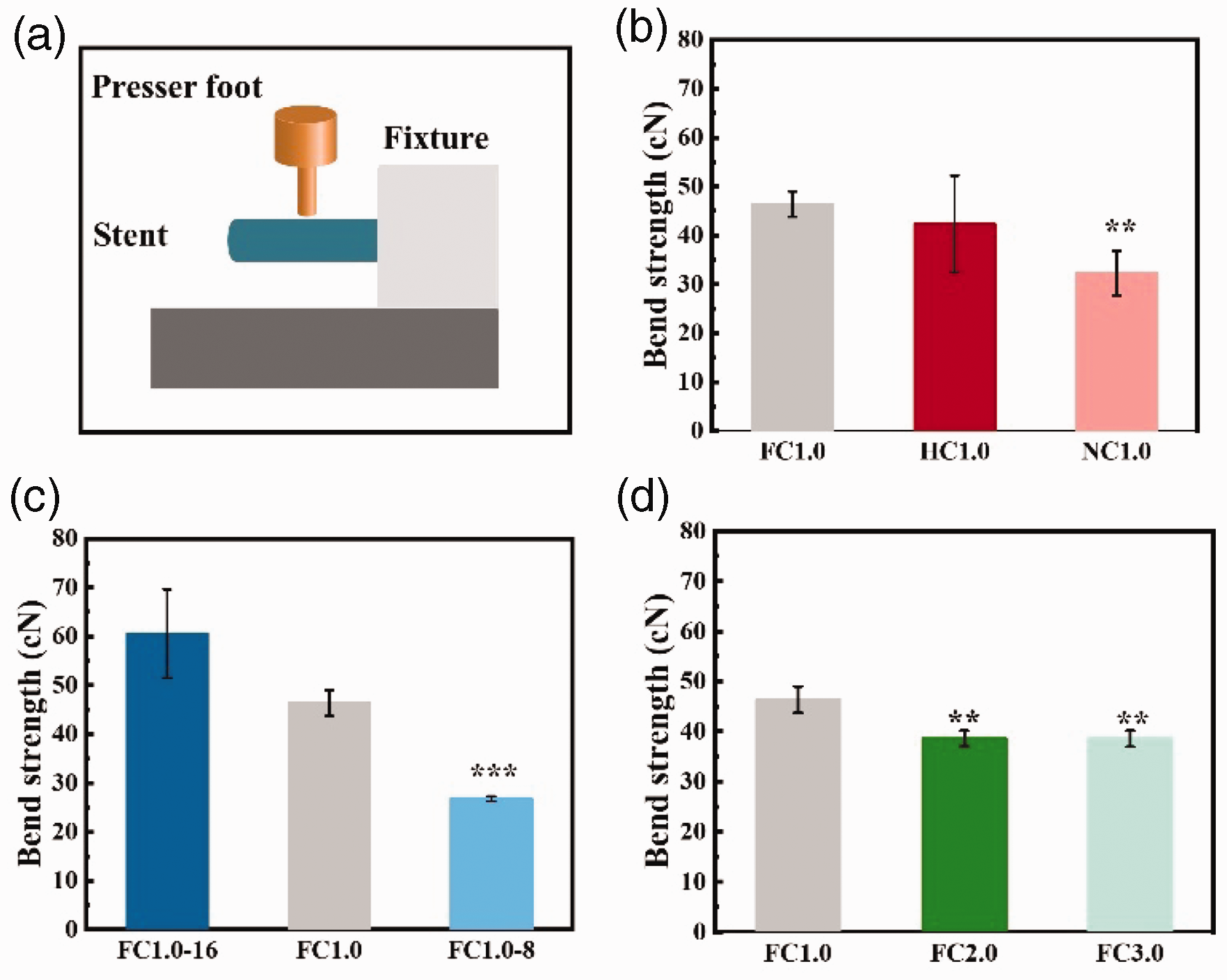
Flexibility results. (a) Experimental diagram of the bending process; (b) Different consistency stent bend strength; (c) Different content stent bend strength and (d) Different pitch stent bend strength.
Antimigration testing
To quantify and compare the antimigration performance of the stent, the stent was inserted into a 15 cm long silicone hose with a diameter of 8 mm32 as shown in Figure 7(a). The stent was fully opened in the hose and a rope was sewn on the top for stretching. A multifunctional strength tester for medical textiles (YG(B) 026G-500; Wenzhou Darong Textile Instrument Co. Ltd., Zhejiang, China) was used. The bottom clamp of the tensile tester was fixed to hold one end of the hose. Then the upper clamp of the instrument clamped the rope and pulled up the stent at a set speed of 10 mm/min. The antimigration force (maximum load value) was output by the instrument.
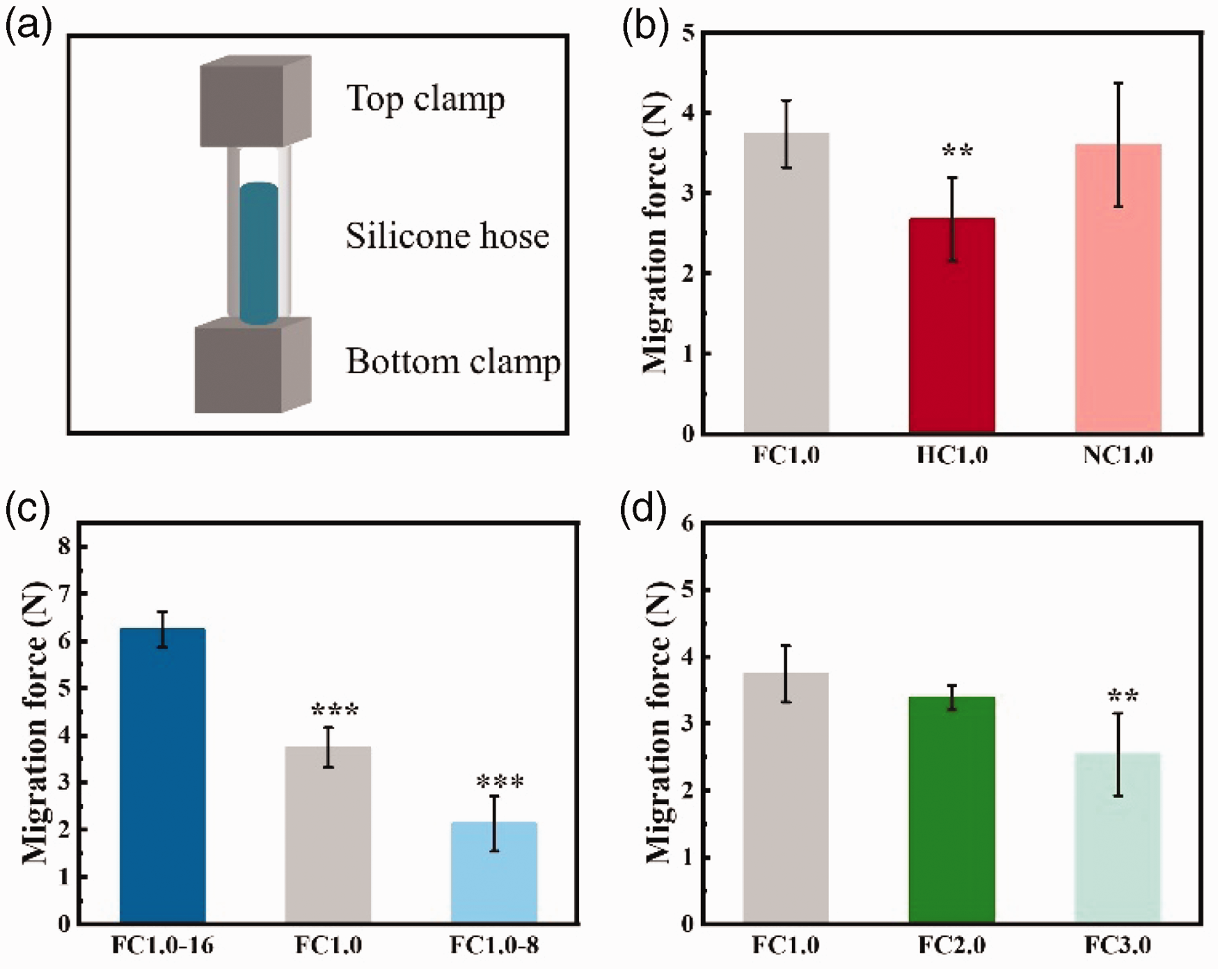
Antimigration results. (a) Experimental diagram of antimigration process; (b) Different consistency stent antimigration strength; (c) Different content stent antimigration strength and (d) Different pitch stent antimigration.
Statistical analysis
All the results were analyzed by one-way analysis of variance (ANOVA) or unpaired Student’s t-test. The values were mean ± standard deviation (SD). Significant differences were present *, *P < 0.05; **P < 0.01; ***P < 0.001; n = 5.
Results and discussion
Morphology/physical parameter of integrated braided stents
The braided process and structure are illustrated in Figure 1 and Figure 2. Figure 2 shows that the metal yarn and polyester multifilament of all stents show symmetrical structure. The surface of the stent was relatively smooth and compact, the appearance is shown in Table 2. The physical parameters of the integrated braided stent are also listed. The inner diameter was 9 mm, and the thickness ranged from 0.46 mm to 0.50 mm. Considering three different structural factors, only the content had a certain effect on the thickness change of the stent. With the increase of the NiTi content by 16, the interweaving points of the metal wires caused the surface of the stent to be uneven and the thickness of the stent decreased. The braid angle of stents was similar, ranging from 55° to 58°. Three braiding factors had almost no effect on the braiding angle. The pitch of stents braided in different consistency and spring pitches was similar to 4.23 interlacing-points per inch. Prototype FC 1.0-8 with the 8 NiTi wire was less than other types of stents.
Gross appearance parameters of the seven kinds of stents
Radial compression property
It can be seen from Figure 3 that three braiding factors all had a certain impact on the compression performance of the stent, which was reflected in the difference in the compression index of different stents. In short, as depicted in Figure 3, consistency had a significant effect on the rapid elastic deformation and energy loss rate of the stent. NiTi content had a significant effect on the compression force and expansion force of the stent, and NiTi spring pitch had a significant effect on the compression force and energy loss of the stent. The compression force of the stent was one of the important indicators to characterize the supportability of the stent. Large compression force means sufficient supportability.
Figure 3(b) suggests NiTi content and spring pitch have a notable effect on compression force while the percentage of consistency has no impact. Among the stents with different consistency, the compression strengths of FC1.0, HC1.0, and NC1.0 were 1048.96 cN, 1023.42 cN and 973.71 cN, respectively. As the percentage of consistency decreased, the stent trend of compression force appeared to decrease slightly. The compression strengths of FC1.0-16, FC1.0, and FC1.0-8 were 1460.2 cN, 1048.96 cN, and 889.99 cN, respectively. As the content decreased, the compression force decreased significantly. For stents with different spring pitches, the compression strengths of FC1.0, FC2.0, and FC3.0 stents were 1048.96 cN, 905.73 cN, and 896.54 cN, respectively. In the compression force index, the difference between different content stents was caused by the effective number of springs, and the stiffness coefficients of different pitch stents were different. When the direction of rotation of the spring was opposite to the stent track, the stent exerted a bending moment on the spring during the braiding process and a small amount of U-shaped spring with an opposite spiral appeared (Figure 3(d)). The U-shape caused the spring stiffness coefficient to decrease, while the spiral caused the spring pitch to decrease. So, consistency has no impact on compression force.
For braided stents containing polymers, the rapid elastic recovery rate and energy loss rate were important characteristics of the compression test. As shown in Figure 3(c), the rapid elastic recovery rates of the three groups of stents were all above 93%, and only the consistency affected the rapid elasticity of the stent. The consistency had a significant effect on the recovery rate, mainly due to the spring error of the metal spring during the braiding process. As for the energy loss rate (Figure 3(e)), which combined effects of compression strength and rapid elastic recovery rate, consistency and pitch were the main influencing factors.
The expansion force of the stent was an indicator of the patency after stent implantation. As depicted in Figure 3(f), among stents with different consistency, the compression forces of FC1.0, HC1.0, and NC1.0 were 157.36 cN, 162.75 cN, and 157.93 cN, respectively. The compression strengths of FC1.0-16, FC1.0, and FC1.0-8 were 233.98 cN, 157.36 cN, and 116.18 cN, respectively. For stents with different spring pitches, the compression strengths of FC1.0, FC2.0, and FC3.0 stents were 157.36 cN, 162.05 cN, and 163.40 cN, respectively. The results implied that NiTi content had a significant effect on the expansion force of the stent.
Proper supporting performance maintains esophagus patency. However, the support strength was strong, resulting in perforation of the esophagus, and was too small to prevent the esophagus from collapsing. 33 When the expansion force of the stent significantly increases beyond the bearing force of the epithelium, it may cause bleeding or other complications. When the radial force of the stent was 190 kPa, close to the tensile strength of the esophageal muscle (210 kPa) 32 according to the literature, it is likely to cause esophageal damage. In addition, to reduce migration, the stent designing criteria involve maintaining as high a compression strength and as low a chronic outward force as possible. 8 Considering the influence of consistency and pitch on the compression strength of the stent, FC1.0, HC1.0, and NC1.0 stents had excellent compression performance.
In particular, stents under repeated cyclic radial compression loading were assessed and compared to the results to assess issues such as restenosis. As depicted in Figure 8, the results suggested that despite plastic deformation, the compression strength and total energy of the seven types of stents showed a downward trend after 10 compressions. After the second compression, the downward trend tends to be flat in compression strength and total. Except for the stents with 8 NiTi metal yarns, the stents’ compression strength and total energy were maintained above 85%. Three indicators showed that the compression mechanics of the stent were maintained well.
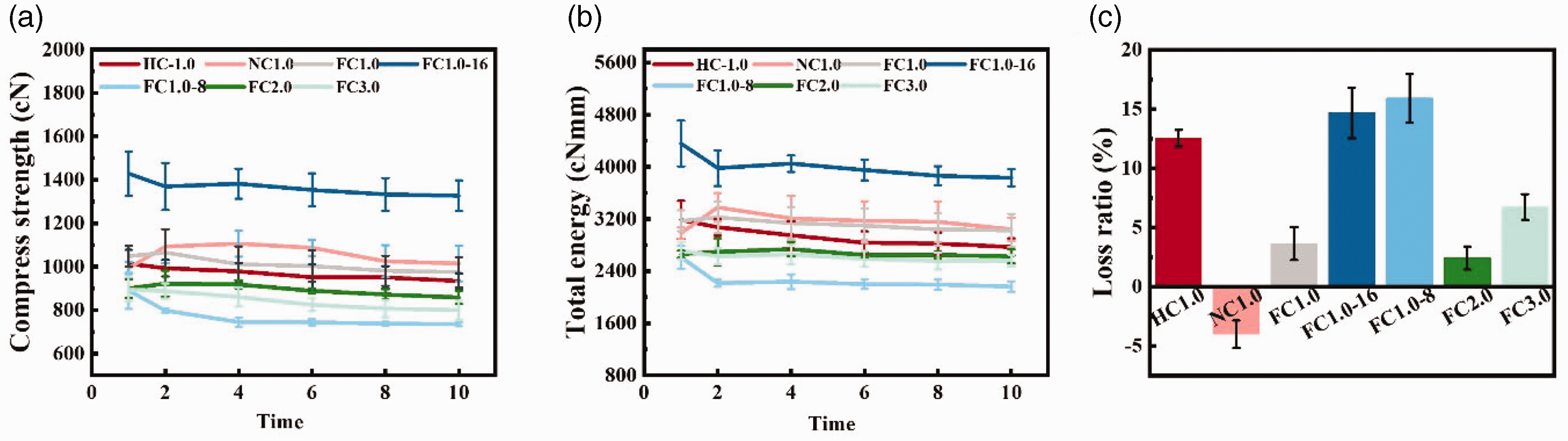
Graph showing the 10th compression stent compared with the first compression. (a) Compression strength; (b) Total energy and (c) Energy loss rate.
Implant performance characterization
As can be seen in Figure 5, the three parameters all had a certain influence on the longitudinal size change of the stent after the implantation process (deployment testing process). In particular, the shrinkage rates of consistency FC1.0, HC1.0, and NC1.0 were 6.74%, 8.15%, and 4.07%, respectively. The shrinkage rates of FC1.0-16, FC1.0, and FC1.0-8 were 2.84%, 6.47%, and 2.56%, respectively. The shrinkage rates of FC1.0, FC2.0, and FC3.0 were 6.74%, 9.42%, and 9.01%, respectively. In terms of consistency, as the inconsistency increased, the stent longitudinal size changes tended to increase first and then decrease. This result was caused by the fact that there were fewer U-shaped sections and the opposite direction during the braiding process of the stent. Therefore, HC1.0 showed maximum compression, but in NC1.0, the stent pitch was already smaller than the other two stents, so the minimum was 4.07%. When the NiTi content was in the stent of consistencies, only FC1.0 had a maximum dimensional change of 6.74%. Because of the high stiffness coefficient of the metal wire in the stent, FC1.0-16 had good resilience after 24 h of implantation, so the size change was small. For FC1.0-8, due to the low metal wire content, the size change was small. When the spring pitch was different, the FC1.0 stent had the largest spring stiffness coefficient, which was beneficial to overcoming the friction between the yarns during the rebound process after the stent was implanted, so the size change was the smallest.
It can be seen from Figure 9 that the compression strength and expansion strength of the stent had changed after being led out by the catheter. After 24 h compression, the compression strengths of different consistency stents were 1220.64 cN, 1149.21 cN, and 1146.99 cN, respectively. Compared with the compression without 24 h, the compression strength increased significantly. In different content stents, the compression strengths were 1424.01 cN, 1220.64 cN, and 768.70 cN. Except for the number of 12 stents, there was no significant difference in the data. In different pitch stents, the compression strengths were 1220.64 cN, 1066.09 cN, and 988.42 cN, respectively. After 24 h, the reduction of the length of the stent was a significant reason for the increase in the compression strength of the stent with different consistency and pitch. However, there was no significant difference in the expansion strength of stents with different consistency and pitch before and after 24 h. This meant that the metal pitch of the stent changes during the compression process, but after the compression rebound, the stent pitch tended to stabilize. For the different content stents, the expansion strengths were 138.63 cN, 192.64 cN, and 68.37 cN; the force value was significantly reduced by 50% compared with before compression.
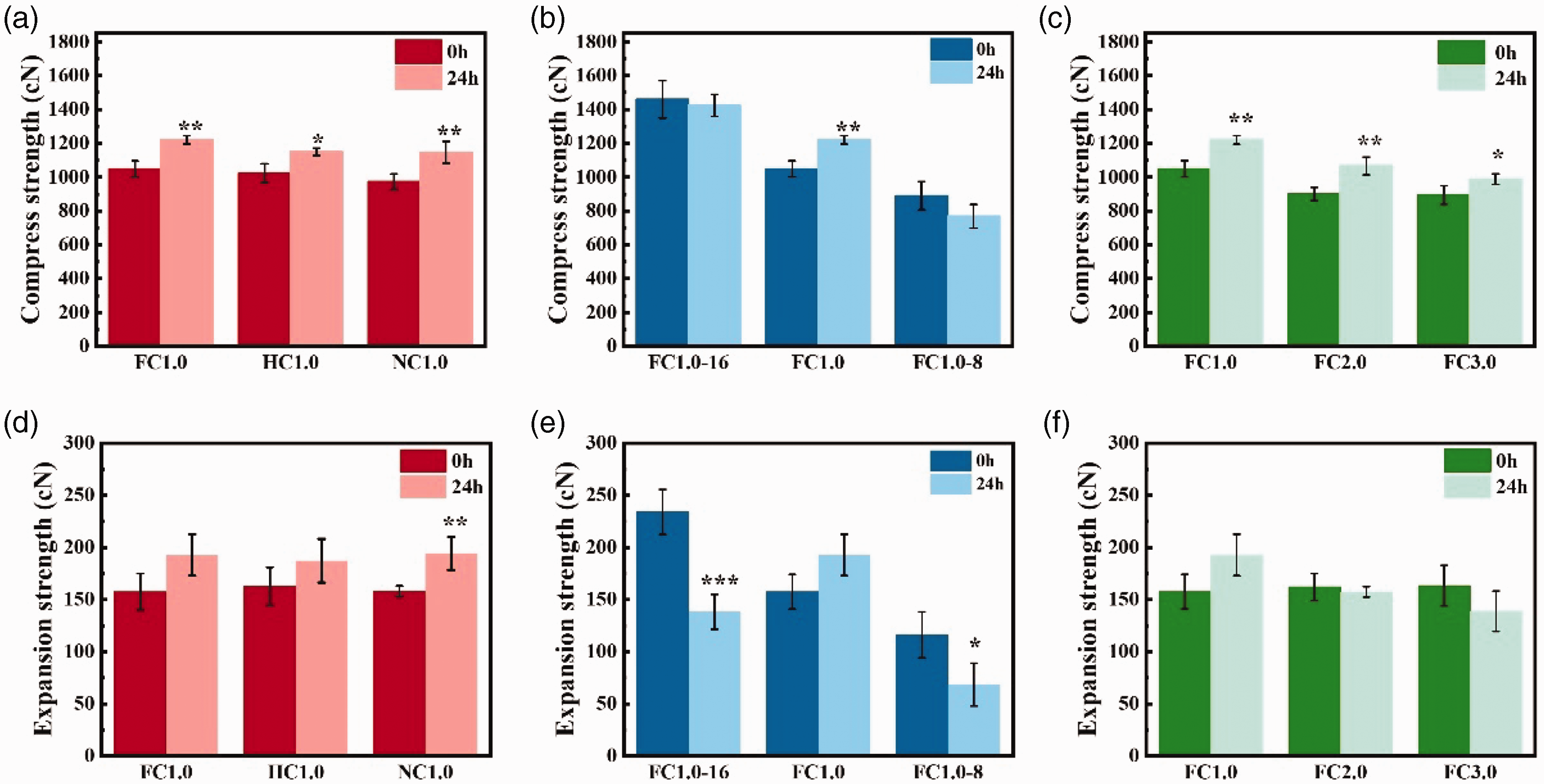
Result of the stent after 24 h compression. (a) Compared with uncompressed treatment, different consistency stent compression strength after 24 h compression; (b) Compared with uncompressed treatment, different content stent compression strength after 24 h compression; (c) Compared with uncompressed treatment, different pitch stent compression strength after 24 h compression; (d) Compared with uncompressed treatment, different consistency stent expansion strength after 24 h compression; (e) Compared with uncompressed treatment, different content stent expansion strength after 24 h compression and (f) Compared with uncompressed treatment, different pitch stent expansion strength after 24 h compression.
Flexibility property
The bending experiment is shown in Figure 6(a). We can see from Figure 6 that the flexibility value of the stent was consistent with the axial performance of the stent. In different consistency stents, the bending forces were 46.35 cN, 42.29 cN, and 32.28 cN, respectively. Due to the problem of the braiding process, the appearance of the U-shaped section minimized its bending force. In different content stents, the bending forces were 60.53 cN, 46.35 cN, and 26.80 cN, respectively. As the content decreased, the bending force of the stent showed a downward trend. Compared with the bending force of the FC1.0-16 stent, consistency reduced the bending force of NC1.0-8 by 50%. In different pitch stents, the bending strengths were 46.35 cN, 38.61 cN, and 38.53 cN, respectively. In this type of stent, the stiffness coefficient was the main influencing factor.
The degree of difficulty for the stent to return to the initial state after bending is called the flexibility of the stent. 34 The lower the axial force meant the better flexibility of the stent. A stent with a low axial force can fit more closely to the inner wall of the esophagus after implantation and cause less damage. In terms of flexibility, the literature points out that when the bending force is less than 150 cN, 9 the stent has good flexibility, which reduces the damage caused to the esophagus after the esophagus stent is implanted. In this study, the FC1.0-16 stent had the maximum bending force, 60.53 cN. Therefore, all seven stents have excellent flexibility.
Antimigration function
When the esophageal stent was deployed in vivo, 75% of the expansion rate implies therapy success. Under adequate patency conditions, we aimed to reduce the migration of the stent. 35 Having a sizeable antimigration ability can prevent the stent from slipping, which means it has excellent antimigration ability.12,32
The results are depicted in Figure 7. For stents with different consistency, the antimigration forces of the stent were 3.74 N, 2.68 N, and 3.6 N, respectively. The existence of the U-shaped section during the braiding process reduced the number of effective coils in the stent, so the antimigration force of the HC1.0 stent was lower than that of the FC1.0 stent, but the pitch of the reverse spring was smaller than the pitch of the spring with the correct direction, making the antimigration force of the NC1.0 stent greater than that of the HC1.0 stent in Figure 7(b). As depicted in Figure 7(c), the antimigration forces of different content stents were 6.24 N, 3.74 N, and 2.12 N. The more effective the spring turns of the different metal yarn content were, the greater the antimigration force was. The antimigration resistances of different pitch stents were 3.74 N, 3.39 N, and 2.54 N. With the same number of effective coils, the greater the stiffness coefficient was, the greater the antimigration force was.
The analysis of the antimigration performance of the stent shows that two standard antimigration methods include structural migration design2,21,36 and external clinical aids. 37 However, the former leads to complications such as esophageal pain, perforation, and fistula; the latter requires a longer operation time and superior suture technology. In this study, the stent used Hooke’s law of spring yarn as an anchor point to increase the antimigration force (f). The force analysis of the structure of the stent in the migration experiment is shown in Figure 10. The sample length (X) of the implanted stent was the same, and μ (friction factor) values were the same. According to the formula, only N (F2) can affect the antimigration force. The FC1.0 stent and NC1.0 stent presented the most significant antimigration force. However, as the NC1.0 wire would be twisted into a U-shaped knot during the braiding process, the FC1.0 stent had a stable structure. In a word, the FC1.0 stent has controllable and appropriate mechanical properties.
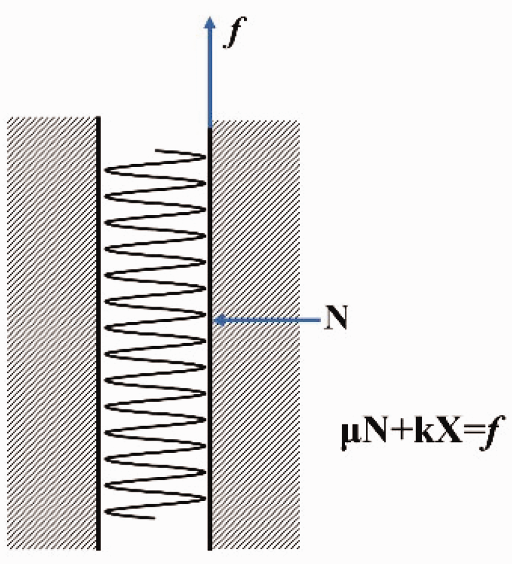
Schematic diagram of the analysis of the antimigration results of the stent.
Conclusions
In this research, we successfully prepared an integrated braided stent with high compression force, flexibility, and high migration resistance by controlling the consistency of NiTi yarn rotation direction and braiding track, NiTi yarn content, and spring pitches. The mechanical properties of the stents were evaluated by compression testing, bending property, and antimigration experiment. Studies have shown that the NiTi content had a significant effect on the compression force in compression testing. Both consistency and content changed flexibility when stents were tested for bending property. As for migration resistance, all three parameters have an impact on this performance. The integrated braided stent with full consistency, 12 NiTi spiral yarns, and spring pitch of 1.00 mm had excellent mechanical properties among all types of stents. The functional performance of braided stents is controlled by material and braiding process. In particular, in this article the NiTi content could have an effect on three kinds of mechanical properties. It offers the opportunity to fabricate stents with tailored mechanical behaviors. In addition, in order to prepare stents with excellent mechanical properties, it is necessary to avoid the inconsistency between the spring rotation and the spindle movement during the braiding process.
Footnotes
Acknowledgements
The authors acknowledge the Fundamental Research Funds for the Central Universities (grant no. 2232022G-01), 111 project 2.0 (grant no. BP0719035).
Declaration of conflicting interests
The author(s) declared no potential conflicts of interest with respect to the research, authorship, and/or publication of this article.
Funding
The author(s) received no financial support for the research, authorship, and/or publication of this article.