




Abstract
Carbon-based flexible wearable sensors have received widespread attention due to their wide application in wearable electronics. This work reviewed the different carbon-based sensors from three aspects, such as fabrication, performance and working mechanisms. Carbon materials mainly included carbon nanotubes, graphene, carbon black and other carbon materials. In particular, carbon nanotubes and graphene can be assembled into various multiscale macrostructures to prepare various forms of flexible sensors, such as films, fibers, yarns or fabrics. Up to now, the reviewed flexible strain sensors in general exhibit high sensitivity, wide sensing range, fast response, long-term stability and durability. However, in the face of complex environmental and multifunctional integration in practical applications, wearable strain sensors need new technological breakthroughs in the preparation process, material synthesis and device integration.
Smart textiles are defined as textiles that interact with their surroundings, 1 are able to sense external conditions or stimuli, and respond and adjust their behavior in an intelligent way. With the advantages of nonintrusive and continuous monitoring, 2 smart textiles can be used in a variety of applications such as health, sports, automotive and aerospace. 3 Smart textiles are currently at the stage of emphasizing one-way functions such as measurement, sensing and monitoring.4,5 Textile-based flexible sensors have good biocompatibility, scalability, real-time monitoring so that they exhibit excellent performance in a variety of applications.6,7 At the same time, textile-based wearable electronic devices also need high performance requirements. The preparation of flexible sensors with high sensitivity and large strain range and seamless integration with textiles is one of the most important factors. Therefore, many researchers have tried to prepared strain sensors through a variety of assembly structures and methods and to improve their strain sensing performance. Until now, main assembly methods were homogeneous blends and ordered structures, such as film, fiber, yarn, and fabric. Film strain sensors were the initial and simple type of textile-based strain sensors, while they cannot be well integrated with textiles as a whole. In order better to release the sensing function in the textiles, fiber, yarn and fabric sensors were proposed according to textile structural features. In other words, the fibers can be twisted to form yarns and the yarns can be woven to form fabrics. Textile materials are considered to be the perfect materials for preparing flexible strain sensors. It is due to their unique textile structure, softness and comfort, resistance to washing, and seamless connection with garments.
The structure of flexible strain sensors usually includes sensitive components, electrodes, and wires. The performance of the sensitive components plays a decisive role in the sensor. Appropriate materials and assembly methods are very important to obtain flexible sensitive components with a large strain range and high sensitivity and stability. To date, various materials, including carbon nanotubes (CNTs),8–10 graphene,11–15 carbon black (CB), 3 conductive polymers, 16 metal nanoparticles and nanowires, 17 and semiconductors, 18 have been used as active ingredients for manufacturing flexible sensors. Among these materials, metal nanoparticles can be used to make sensors with higher sensitivity, but it was in a limited sensing range and stretchability. 19 In addition, due to the poor performance of the chemical stability and repeatability of metal nanowires, it was difficult to use metal nanowires to manufacture stable sensors. 20 Similarly, conductive polymers with poor stability and conductivity were also difficult in producing high-performance sensors. 21 In contrast, carbon-based materials are well suited for use in human motion detection and human health monitoring due to their good electrical conductivity and stretchability. Therefore, they are widely used in wearable sensors. CNTs have excellent electrical conductivity (up to 107 S/m), high aspect ratio, excellent flexibility, excellent stability, and are not easily damaged under tensile and bending conditions. 22 Graphene has many advantages such as high thermal conductivity, high current density, ballistic transport, light transmission, nanoscale super-hydrophobicity and chemical inertness. 23 Compared to CNTs, graphene-based strain sensors show higher sensitivity as well as lower strain range due to the small size, easy sliding sheet structure, and poor stretching capability. Furthermore, CB is cheaper and easier to use than CNTs and graphene and exhibits good dispersion, but cannot be used alone and is generally mixed with polymers. 24
The operating principles of flexible strain sensors include the conductive network between materials, tunneling effect and crack extension. 25 Flexible strain sensors with different assembly structures including film, fiber, yarn, fabric, and work by different mechanisms. In general, porous, folded and overlapping structures of conductive materials favorably increase the strain range of strain sensors, but lead to a decrease in sensor sensitivity. 26 Conversely, cracked, multilayer structures of conductive materials increase the sensitivity of the sensor and decrease the strain. 27
Based on the current development of smart textiles, this review aims to summarize the preparation methods of various carbon-based flexible sensors, including carbon-based film strain sensors, carbon-based fiber strain sensors, carbon-based yarn strain sensors and carbon-based fabric strain sensors. In addition, related performance characteristics of sensors fabricated by different methods are also discussed based on different mechanisms. In the end, the remaining challenges in this field and the prospects of carbon-based flexible sensors are proposed.
Carbon-based film strain sensors
Membrane strain sensors are the original sensor type and have been widely used in the applications of skin-type sensors. 28 They exhibited excellent stretching cycle performance, not only can sense touch pressure, but can also be bent into any shape needed. However, film strain sensor must attach to the surface of the object (such as skin or cloth) before work and fall out easily. In addition, only local strain signals can be obtained. This problem has limited the development and application of the film strain sensor, particularly in textile wearable devices.
Fabrication of carbon-based film strain sensors
CNT-based film strain sensors
The film sensor is manufactured by attaching a carbon nanomaterial with a thin film structure to the surface of the substrate. The strain sensor usually consists of two layers, namely the nano-carbon layer and elastic polymer matrix layer. The main fabrication methods of CNT films were wet and dry methods. Wet methods include spin coating, 29 the vacuum filtration process, 30 spray coating, 31 printing, 32 layer-by-layer (LBL) assembly, 33 and so on. Kao et al. 34 successfully fabricated a fully inkjet-printed strain sensor by using CNT sensing film and silver conductive film. Based on the digital image of inkjet printing technology, as shown in Figure 1, 34 a uniform and stable resistance CNT film is obtained through multipass printing and pattern rotation. Controlling the uniformity of the film thickness significantly affected the stability of the sensor, which was the major challenge for the preparation of sensors using inkjet printing. The LBL assembly method has been reported as an effective preparation method for film sensors. This method used electrostatic interaction, hydrogen bond or covalent bond interaction 35 to soak and dry the substrate repeatedly. The key problem to form a LBL film sensor was similar to an inkjet-printed strain sensor. In addition, the interaction between materials was weak, which reduced the electrical properties of the film. Functionalization of carbon-based materials is an effective method to produce carbon-based films. Generally, wet methods are not only simple, low cost, but are also efficient in preparation and can be put into large-scale use. In addition, the conductive film is also relatively uniform, while they require surfactants or chemical functionalization to help CNTs uniformly disperse in the solvent.

The fabrication of the fully inkjet-printed strain sensor. 34
Different to the wet method, CNT film prepared by the dry method exhibited neat arrangement, high purity and controllable CNT length. Yamada et al. 36 reported a wearable stretchable sensor made of neatly arranged single-walled carbon nanotube (SWCNT) film. As shown in Figure 2, 36 first, a water-assisted chemical vapor method was used to grow a SWCNT film vertically on the surface of the patterned catalyst, and the length of the SWCNTs can be arbitrarily controlled within a certain range by adjusting the growth time. Then the films were assembled on flat dog-bone polydimethylsiloxane elastic substrates, keeping the arrangement direction of SWCNTs perpendicular to the strain axis. The advantage of this method is that it can be used to prepare film materials of any length. This provides more possibilities for the future flexible sensor business. However, the dry preparation process is complicated, costly, and time-consuming, which is not conducive to the mass production of sensors. How to simplify the process so that it can be mass-produced has become a key issue in the sensor field of the future.
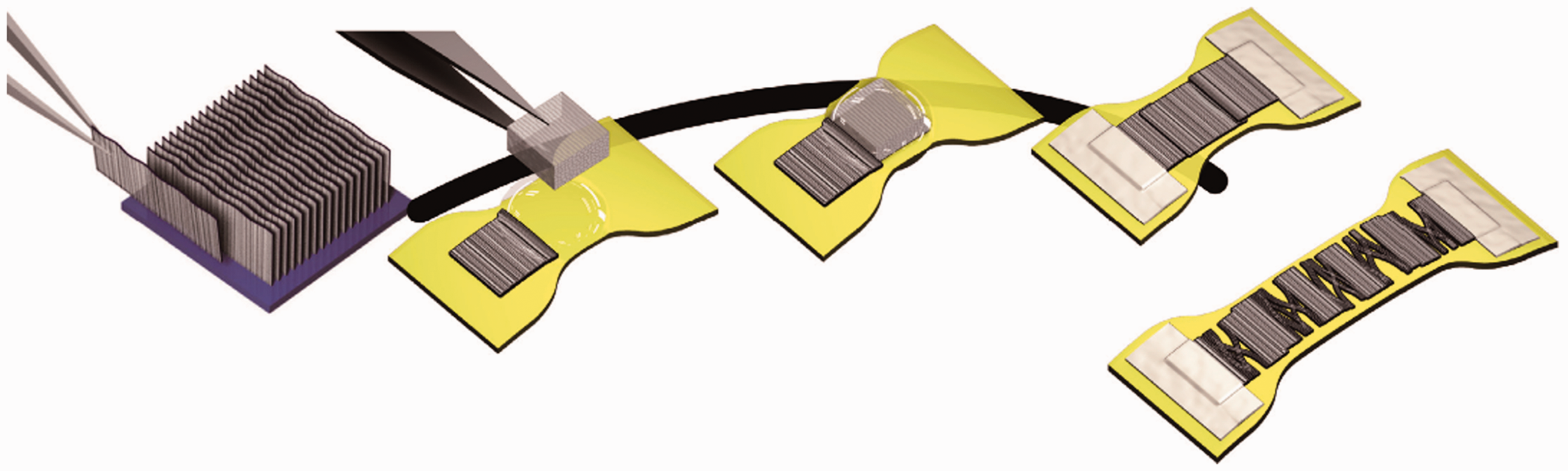
Key steps in fabricating the single-walled carbon nanotube (SWCNT) strain sensor. 36
Graphene-based film strain sensors
Due to the strong π–π interaction between two-dimensional graphene layers, graphene is the easiest to assemble into film material. Graphene film materials can be directly prepared by chemical vapor deposition (CVD) or assembled by graphene oxide (GO). The former was of high quality, but the preparation and transfer conditions of the graphene film were harsh, the latter preparation methods included dip coating, 37 spin coating, 38 rod coating or blade coating, 39 casting, 40 spray coating, 41 and self-assembly.42,43 These GO films should be treated by chemical methods or thermal treatments to achieve good electrical conductivity.
Liu et al. 44 reported a graphene composite film strain sensor, which was prepared by sandwiching a polymer layer between the graphene layer and the substrate. Styrene-acrylate emulsion was used to form a polymer film between graphene and substrates by spray coating, as shown in Figure 3(a). Graphene can be closely integrated with the substrate material as the emulsion acted as an effective binder. In addition, the spraying method used spraying equipment to spray paint onto the surface of the substrate. 45 Compared with other deposition methods, spray coating was fast, low cost and suitable to prepare large and even complex-shaped surface film attachment to cloth. In addition, this sensor can be tuned over a wide range of values by adjusting the deposition parameters. Zhang et al. 46 presented an alternative approach combined with LBL self-assembly, as shown in Figure 3(b). It allowed a controllable fabrication of a graphene/polymer film strain sensor on flexible substrates of polyimide with interdigital electrodes. Carboxylated graphene and poly (diallyldimethylammonium chloride) were exploited to form a hierarchical nanostructure due to electrostaticaction. A highly sensitive strain gauge based on graphene piezoresistivity was presented by Gamil et al. 47 Monolayer and multilayer graphene films have been grown on a copper (Cu) substrate by CVD and then transferred onto a silicon dioxide/silica (SiO2/Si) substrate using polymethyl methacrylate to fabricate it (Figure 3(c)).
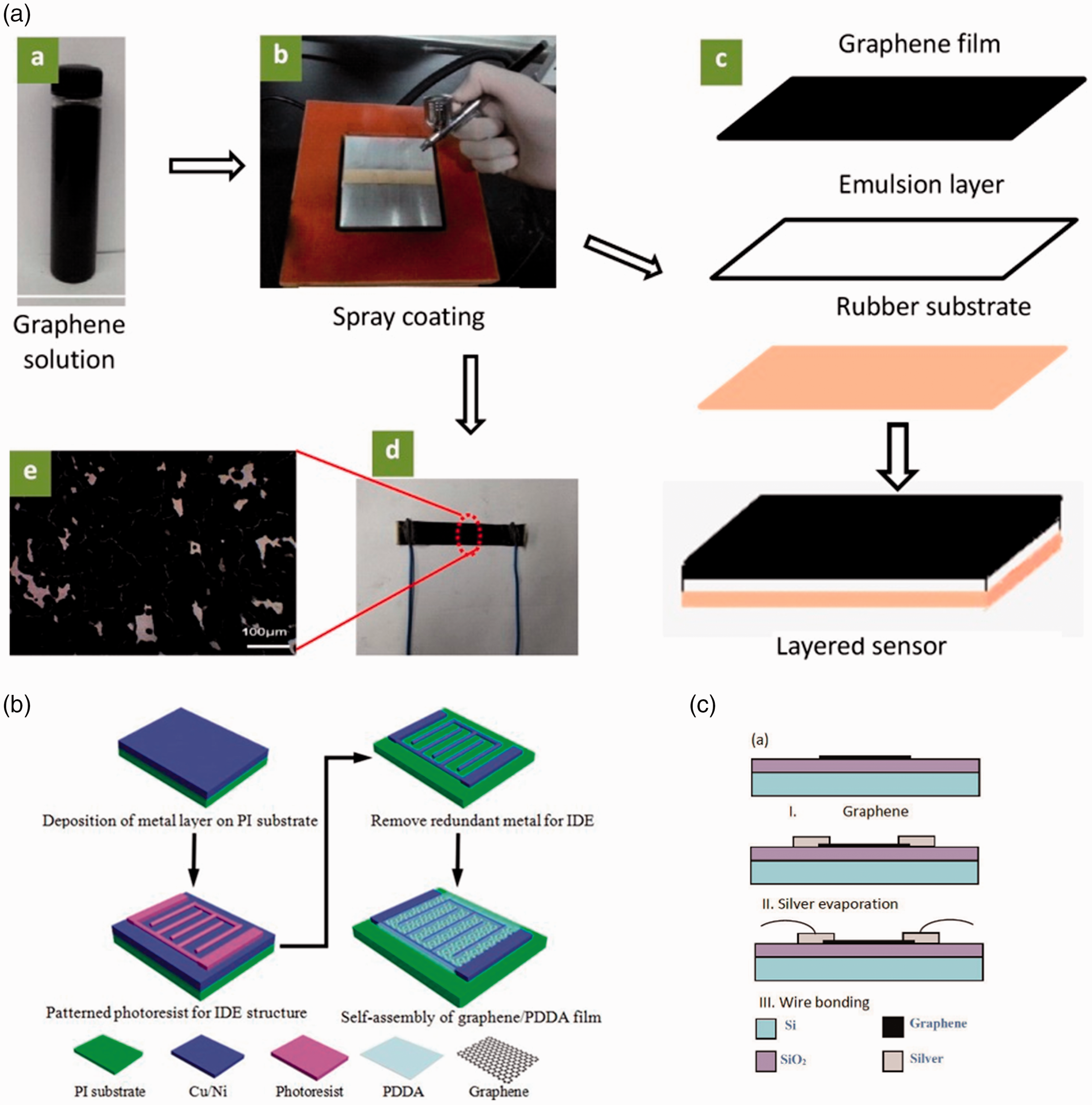
Preparation of graphene-based film strain sensor. (a) Illustration of the fabrication of the spraying method of the graphene-based film strain sensor. 44 (b) Illustration of the fabrication of the layer-by-layer self-assembly graphene/polymer film strain sensor. 46 and (c) Illustration of the fabrication of the chemical vapor deposition (CVD) graphene film strain sensor. 47
CB-based film strain sensor
CB is a common carbon-based conductive filler compared with the above graphene materials. It has the advantages of wide sources, light weight, large specific surface area, stable electrical conductivity, and low price. The CB was distributed in the polymer matrix as a grape chain structure with high dispersion which resulted in high conductivity. 24 CB can bond better with polymers due to a small amount of carboxyl groups, ester groups and other groups on its surface. CB is often used as a filled conductive polymer material due to the reinforcing effect and is widely used in textile flexible sensing.
Furthermore, Xia et al. 48 prepared a flexible capacitive strain sensor encapsulated by a polydimethylsiloxane/CB hybrid electrode. Polydimethylsiloxane was cast and cured into a continuous silicone layer, as shown in Figure 4(a). This method is not only simple and low cost, but powerful, which provides the possibility for expanding the usability of the wearable sensor system. More importantly, a large number of studies have demonstrated that hybrid two or more fillers can compensate for the shortcomings of one filler to improve the performance of the composite. Therefore, the composite material showed a high synergy between the fillers which resulted in good piezoresistive properties. As shown in Figure 4(b), Kurian et al. 49 cast the graphene-CB-silicone rubber (G-CB-SR) in a mould to prepare a composite film strain sensor. They studied the effects of different geometric shapes on electrical conductivity and piezoresistive properties of the composite. Xiao et al. 50 manufactured a crack-based strain sensor for polyvinyl chloride (PVC)/CB composites. The flexible conductive circuit and PVC/CB composite material are transferred to the polyimide substrate by screen printing to obtain the required geometry. It can be seen that the different geometric shapes have a certain impact on the performance of the sensor. Controlling the film shape and generation of microstructures has become the main research direction to optimize the performance of this type of sensor.

Performance and mechanism of carbon-based film strain sensors
CNT-based film strain sensor
Figure 5(a) compares the sheet resistivities and thicknesses of eight-layer CNT films obtained by unidirectional printing, 34 180° rotation, and 90° rotation. It can be seen that the pattern of rotation reduced the sheet resistance. This is due to the fact that multiple printing after rotation provided a more uniform film, resulting in low and stable resistance. In addition, the performance of the strain sensor is not only related to the uniformity of the film, but is also affected by the dispersibility of the CNT. As shown in Figure 5(b), 51 the multi-walled carbon nanotube (MWCNT) surface was modified by a silane coupling agent (KH550) and sodium dodecyl benzene sulfonate (SDBS). The nonlinear error, hysteresis error and repeatability error of the piezoresistivity of modified MWCNT/polyurethane decreased 9%, 16.72% and 54.95% compared with raw MWCNT/polyurethane, respectively. The piezoresistive response of modified MWCNT/polyurethane had better stability than that of raw MWCNT/polyurethane composites. The hydrophilicity of conductive particles and the interface between conductive material and polymer were increased by surface modification, methods such as the introduction of functional groups on the surface of CNTs.

Performance and mechanism of carbon nanotube (CNT)-based film strain sensor. (a) Sheet resistivities and thicknesses of eight-layer CNT films by unidirectional printing, 180° rotation, and 90° rotation. 34 (b) Photographs of multi-walled carbon nanotubes (MWCNTs) dispersed in N,N-dimethylformamide and placed for 0 h, 12 h, and 24 h. #1 modified MWCNTs by using KH550 and sodium dodecyl benzene sulfonate (SDBS); #2 modified MWCNTs by using SDBS; #3 modified MWCNTs by using KH550; and #4 raw MWCNTs. 51 (c) Average island width (blue) and gap (red) versus strain for initial loading. Error bars indicate standard deviation. (d) Paper model of the unstrained and strained states. 36
Yamada et al. 36 reported a wearable stretchable sensor made of neatly arranged SWCNT film. As shown in Figure 5(c) and (d), the nanotube film breaks into gaps and islands when stretched. 36 The gaps between tube bundles can withstand strains up to 280% (50 times that of traditional metal strain sensors). Besides this, the wearable stretchable sensor showed high durability (it can withstand 10,000 cycles under 150% strain), fast response (14 ms delay time), and low creep (only 3.0% under 100% strain). The sensor can be mounted on socks, bandages and on gloves to monitor accurately large movements of the human body.
Graphene-based film strain sensor
Strain sensors based on a layered graphene composite film can effectively improve their sensitivity. 44 Under the action of the adhesive, the graphene and the base material are tightly combined with a gauge factor (GF) of 6–35, as shown in Figure 6(a) and (b). Moreover, Chun et al. 52 proposed a stretchable graphene film sensor that can detect all lateral and longitudinal strains in a single sensor element with a unique structure. The sensor showed a high stretchability of 150% in both cases, and the GF in the two cases was 8.56 (0–100%) and 19.8 (100–150%). Zhang et al. 46 further investigated the sensor performance of a graphene/polymer film strain sensor on flexible substrates of polyimide with interdigital electrodes. The sensor exhibited not only excellent response and reversibility behavior as a function of deflection, but also good repeatability and acceptable linearity. A highly sensitive strain gauge based on graphene piezoresistivity was presented by Gamil et al. 47 The fabricated gauges based on monolayer and multilayer graphene films showed a stable GF of 255 and 104 within the applied temperature range, respectively (Figure 6(c) and (d)).

Performance and mechanism of graphene-based film strain sensor. (a) Strain-induced resistance change for devices with different sheet resistance. (b) Extracted gauge factor (GF) versus initial resistance. 44 Relationship between applied strain and GF for (c) monolayer and (d) multilayer graphene films. 47
CB-based film strain sensor
Polydimethylsiloxane/CB hybrid film sensor developed by Xia et al. 48 was based on low-cost materials silicone polydimethylsiloxane and CB. In the strain range (3% to 47%), the capacitance the GF was approximately constant at 0.86. It can work continuously for 10,000 strain cycles and can sense up to 50% strain. Through the integration with the elbow strap, the wearability and high flexion angle motion detection are realized, and the 90° motion range can be clearly detected. The electrical conductivity and piezoresistive properties of the G-CB-SR thin-film composite strain sensor prepared by Kurian et al. 49 were influenced by geometric shapes. The electromechanical response of the composite material shows a high degree of reversibility and durability, as shown in Figure 7(a) and (b). It can be stretched to 300%. The GF depended on the composition of the composite material (Figure 7(c)). Xiao et al. 50 demonstrated a crack-based strain sensor for PVC/CB composites. After 5000 times of bending, the PVC/CB surface formed a stable crack shape (Figure 8(a)), which greatly improved the sensitivity of the strain sensor (Figure 8(b)). Corresponding GFs were equal to 741 and 1563 gauge under the tensile and compressive strains (Figure 8(c) and (d)), respectively. It should be noted that this crack-based sensor was suitable for human activity detection in flexible and wearable electronic devices. It can be seen from the above research that the manufacture of microstructures can greatly improve the sensitivity of the sensor. In addition to the direction of cracks, the sandwich structure also helped to prepare high-sensitivity sensors. This provides new ideas for high-sensitivity wearable electronic devices.
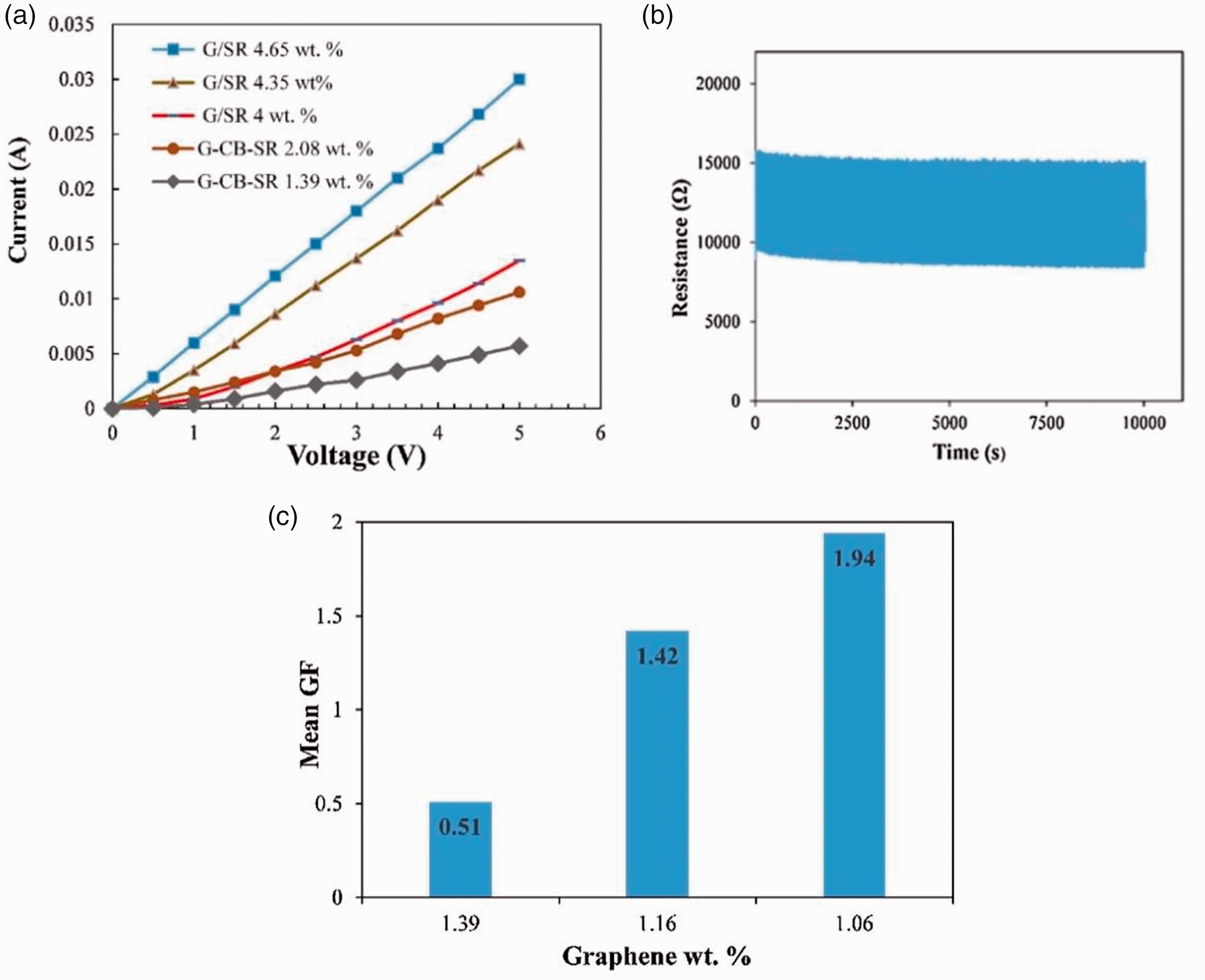
Performance and mechanism of graphene-carbon black-silicone rubber (G-CB-SR) film strain sensor. (a) I–V characteristics of graphene/silicone rubber (G/SR) and G-CB-SR composites with different graphene content (wt.%). (b) Long-term stability of a strain sensor for 500 cycles. (c) Normalized resistance-strain curve of graphene (wt.%) – gauge factor (GF). 49

Performance and mechanism of polyvinyl chloride (PVC)/carbon black (CB) film strain sensor. (a) Scanning electron micrograph (SEM) of printed PVC/CB strain sensor. Left-hand side SEM image shows crack formation stage, middle propagation stage, right-hand side saturation stage (SEM image picked 10, 3000 and 9000 bends, respectively). (b)–(c) Sensor resistance change and corresponding gauge factors (GFs) under variable tensile and compressive strains. (d) Compressive strain performance of PVC/CB sensor with and without cracks (red and black curves, respectively) and of PVC/carbon nanotube (CNT) strain sensor (blue curve) as a function of the normalized current change (ΔI/I0). 50
Table 1 summarizes the detailed specifications of the carbon-based thin film strain sensor. From these results, it can be concluded that assembling the strain sensor through a combination of adhesives can improve the stability and durability of the sensor, thereby improving the sensitivity of the sensor to a certain extent. In addition, this effect can also be achieved through certain physical and chemical effects. For example, electrostatic interactions between materials and the creation of new chemical bonds. However, the interaction between these materials affected their own conjugate structure, making the conductivity of carbon-based materials decrease. To balance the electrical properties and stability between the carbon-based materials and the substrate is the main difficulty for carbon-based film sensors. In addition, obtaining a film with uniform thickness through a specific method such as pattern rotation printing is an effective method to reduce the resistance of the film.
Summary of performance of flexible film strain sensors

PDMS: polydimethylsiloxane; CB: carbon black; GNP: graphene nanoplatelet; SR: silicone rubber; PVC: polyvinyl chloride; CNT: carbon nanotube; CVD: chemical vapor deposition; GF: gauge factor.
Summary of performance of flexible fiber strain sensors
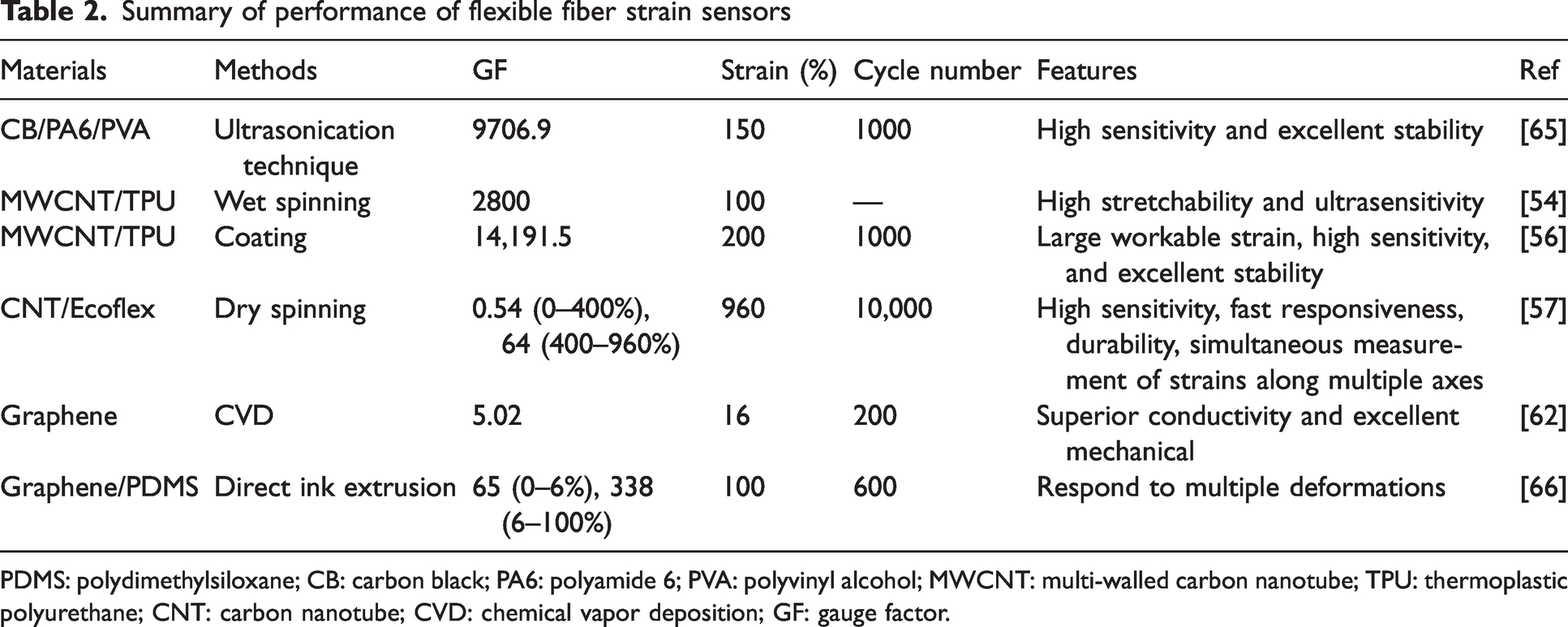
PDMS: polydimethylsiloxane; CB: carbon black; PA6: polyamide 6; PVA: polyvinyl alcohol; MWCNT: multi-walled carbon nanotube; TPU: thermoplastic polyurethane; CNT: carbon nanotube; CVD: chemical vapor deposition; GF: gauge factor.
Carbon-based fiber strain sensors
Compared with film strain sensors, fiber strain sensors are more flexible and suitable in textile wearable devices in various textile products. They can be become one intrinsic part of textiles. However, most fibers do not possess electrical conductivity, and even conductive fibers (e.g. graphene fibers) have disadvantages such as poor strength, low elongation and elasticity, and fragility under external forces, which hinder their promising applications in strain sensors. Therefore, several techniques have been employed to eliminate these drawbacks in order to fabricate fiber optic strain sensors. Nano-textile technology can prepare fiber sensors with a diameter of several to tens of microns, creating conditions for the preparation of high-stretch, high-sensitivity carbon-based fiber strain sensors are summarized in Table 2. 53 The ideal wearable strain sensor should have the advantages of light weight, long life, flexibility, and comfort, fiber structure can meet the above requirements.
Fabrication of carbon-based fiber strain sensors
CNT-based fiber strain sensors
Similar to film strain sensors, the manufacturing process of CNT-based fiber strain sensors can be divided into wet and dry methods. He et al. 54 report a highly sensitive wearable strain sensor based on highly stretchable MWCNT/thermoplastic polyurethane (TPU) fiber manufactured by wet spinning, as shown in Figure 9(a). Gao et al. 55 sprayed CNT dispersion on polyurethane fibers, combined with electrospinning over-twisting technology to turn two-dimensional strips into one-dimensional spiral yarns (Figure 9(b)). The composite fiber sensor exhibited high sensitivity and excellent elastic recovery. Chen et al. 56 coated nanomaterials on the surface of spandex to obtain elastic fiber strain sensors, as shown in Figure 9(c). The conductive coating quality was closely related to its solvent. For example, in the coating process, the coating continuity determined its initial conductivity of the fiber sensor. Second, the viscosity and boiling point of the solvent should be minimized in order to improve the operability of the coating method. It should be noted that uneven evaporation of the solvent can affect the conductive network. In addition, dry methods, including direct spinning from CNT arrays and CNT aerogels during the CVD process, have been investigated to produce CNT fibers. Ryu et al. 57 reported on an ultra-highly stretchable wearable device made of dry-spun CNT fibers.
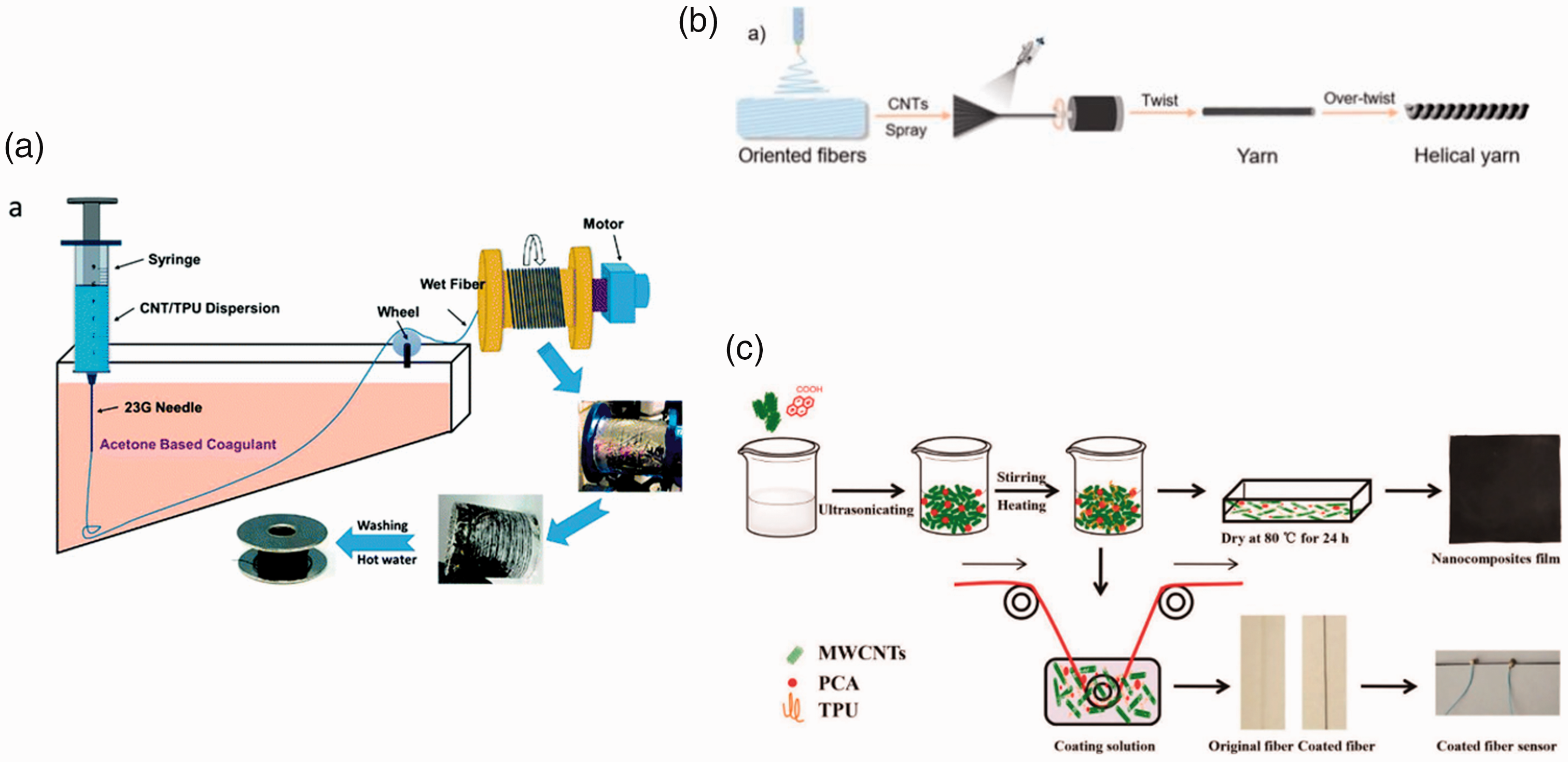
Fabrication of carbon nanotube (CNT)-based fiber strain sensor. (a) Schematic illustration of the wet spinning process for multi-walled carbon nanotube (MWCNT)/thermoplastic polyurethane (TPU) fibers. 54 (b) The fabrication scheme of the helical CNT/polyurethane yarn. 55 and (c) Schematic diagram of the strain sensing fiber fabrication using the coating technique. 56
Graphene-based fiber strain sensors
Graphene fibers can be prepared by CVD,58–60 electrospinning, 61 and wet spinning. The graphene fiber prepared by CVD has a compact structure and excellent electrical conductivity. Electrospinning technology was difficult to use directly to prepare nano-scale fibers, which limited the development of electrospinning in the preparation of pure graphene fibers. However, it is possible to prepare a variety of different graphene composite fibers. The wet spinning operation is the most simple way. The structure and performance of graphene fibers can be improved by changing the composition and concentration of the coagulation bath, the structure and the spinning method. The difference of the CVD method from wet spinning is that it does not require a coagulation bath, and the subsequent process does not require repeated washing and drying.
Wang et al. 62 achieved the mass production of graphene nanofibers (>100 cm) grown by core-sheath CVD, as shown in Figure 10(a). They exhibited higher electrical conductivity and mechanical properties than fibers made with GO. Wang et al. 63 reported a graphene-added polydimethylsiloxane fiber with high tensile properties and good light transmittance (Figure 10(b)).
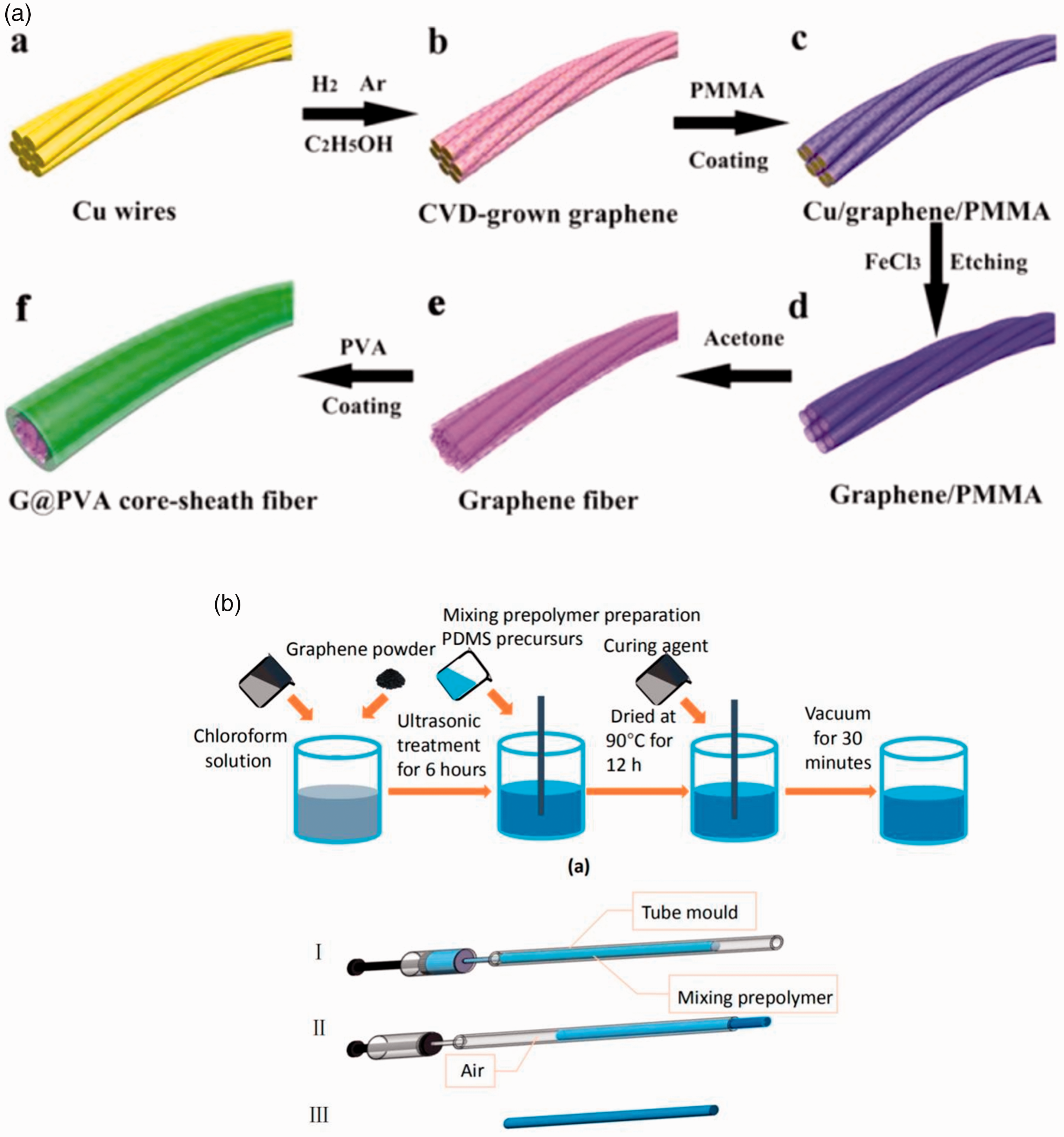
Fabrication of a graphene-based fiber strain sensor. (a) Schematic illustration of the fabrication process of graphene/polyvinyl alcohol (G/PVA) fibers. 62 and (b) Schematic diagram showing the preparation of the mixture of prepolymer and polydimethylsiloxane fiber preparation process.63
CB-based fiber strain sensors
The measurement range of the above carbon-based fiber sensors is limited to small strains, but sensors prepared by blending CB with fibers can overcome this problem. Therefore, CB is usually used to coat fibers to prepare sensors. However, the high concentration CB blend showed poor spinnability, and the prepared fiber possessed low mechanical properties. The traditional coating method is achieved by using an adhesive, while the conductivity of the sensor prepared by this method decreased significantly as the washing cycle increased. Jin et al. 64 adopted a real fiber matrix solvent to disperse CB without applying a binder. As shown in Figure 11(a), the CB can evenly penetrate the fiber surface and become a part of the fiber structure. Jin et al. 64 used polyamide 6 (PA6) fiber as the substrate. CB-coated PA6 fiber was prepared by the dissolution coating method (Figure 11(b)) and the traditional coating method, respectively. The durability of the coating and the influence of various factors that cause the change of tensile resistance are studied. In addition, Zhan et al. 65 proposed a simple and low-cost method to manufacture strain sensors with good mechanical properties and excellent sensing capabilities. They used ultrasonic technology to coat CB particles on the surface of PA6 fibers to build a conductive channel, and then immersed it in the polyvinyl alcohol (PVA) polymer matrix to protect the conductive network, as shown in Figure 11(c).

Performance and mechanism of carbon-based fiber strain sensors
CNT-based fiber strain sensors
The MWCNT/TPU fiber wearable strain sensors reported by He et al. exhibited a wide strain range of 5–100% and a tensile strength of 28 MPa and the GF was about 2800 (Figure 12(a)). 54 A sewing machine can be used to sew the composite fiber to a highly stretchable elastic bandage (Figure 12(b)) to detect various human movements, as shown in Figure 12(c) and (d). The sensor prepared by spraying with electrostatic spinning and twisting technology presented a large strain range of 900% and excellent elastic recovery (the resistance only decreased 1.9% after 100 cycles), 55 as shown in Figure 13(a) to (c). A tensile fracture length of 1700% benefited from the re-lapped surface cracks to form a new conductive network after the strain released. In addition, Chen et al. 56 uniformly coated nanomaterials on the surface of spandex to obtain elastic fiber strain sensors (as shown in Figure 14(a)). As shown in Figure 14(b), the sensitivity coefficient was 6.7 in the strain range of 0–20%, and can reach 14,191.5 in the range of 170–200% strain, and good stability (>1000) times. The sensor has also been successfully applied to human motion monitoring (as shown in Figure 14(c)), such as joint motion, facial micro-expression and voice recognition. Because of its unique structure, the research of CNTs has great theoretical significance and potential application value. An ultra-highly stretchable wearable device made of dry-spun CNT fibers exhibited excellent tensile strain along the longitudinal axis of the CNT. 57 When the highly oriented CNT fiber array was placed on an elastic substrate, it produced a uniform stress distribution on the entire device during stretching, tolerance (greater than 900%) while maintaining high sensitivity, fast response time and high durability. In addition, devices with biaxially oriented CNT fiber arrays showed independent cross-sensitivity, which facilitated simultaneous measurement of strain along multiple axes. It also demonstrated the potential applications of the device, such as strain gauges, single-axis and multi-axis motion sensors.

Performance and mechanism of multi-walled carbon nanotube (MWCNT)/thermoplastic polyurethane (TPU) fiber strain sensor. (a) Relative change in resistance versus strain of MWCNT/TPU fiber-based strain sensor. 54 (b) Photograph of the composite fiber stitched onto an elastic bandage, and the schematic model of a composite fiber-based wearable strain sensor for detecting human motion. (c) and (d) Photograph of the sensors attached to the index finger and the resistance response of the sensors in detecting finger motion during bending. 54

Performance and mechanism of carbon nanotube (CNT)/polyurethane helical yarn strain sensor. (a) The loading–unloading curves during different strains, showing a good recoverable property of the CNT/polyurethane helical yarn even at 900% stretching. (b) The good conductivity of the helical CNT/polyurethane yarn demonstrated by LED light during the stretching process and (c) The resistance variation curves of the CNT/polyurethane helical yarn during 720° torsion cycles. 55
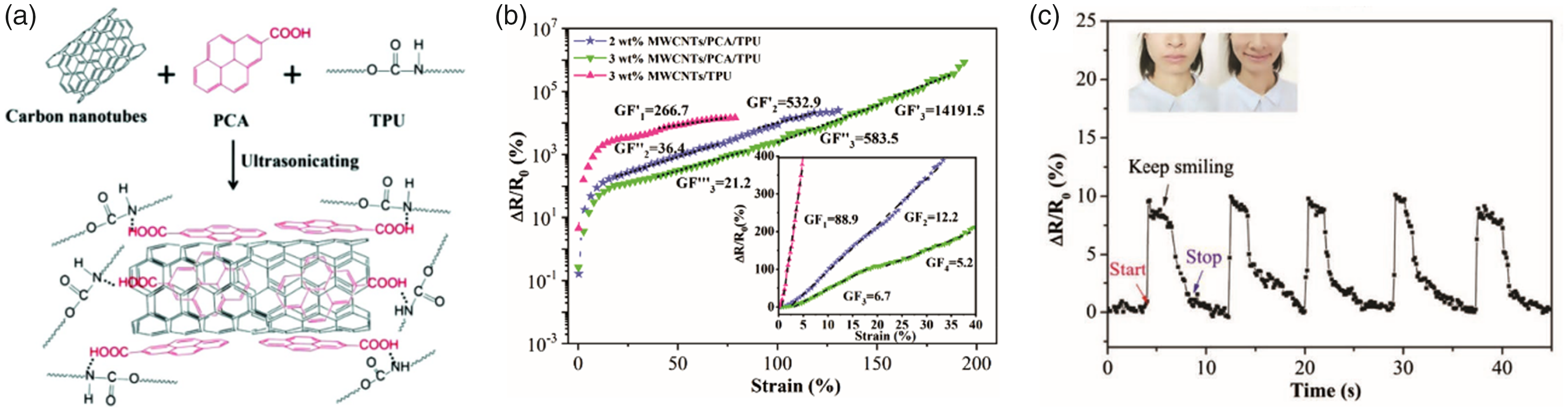
Performance and mechanism of carbon nanotube (CNT)/spandex helical yarn strain sensor. (a) A schematic diagram of enhanced interfacial interaction between polymer and nanotube. (b) Relative resistance change of the modified and control sample fiber strain sensors as a function of tensile strain; the gauge factor (GF) is calculated from the curve and (c) Recording of human motions using the nanocomposite-coated fiber sensor. 56
Graphene-based fiber strain sensors
Graphene nanofibers (>100 cm) grown by core-sheath CVD showed higher electrical conductivity (9.6 × 10³ S/m) and mechanical properties (tensile strength and Young’s modulus of 40 MPa and 2 GPa) than fibers made with GO. 62 Coating on the insulating outer layer of PVA showed a large stretchability of up to 16% and a high conductivity of 9.6 × 10³ S/m, as shown in Figure 15(a) and (b). This core-sheath fiber strain sensor shows greatly improved performance, including high sensitivity (GF up to 5.02) and cycle stability (almost no change in resistance after 200 stretch–release cycles). The graphene-added polydimethylsiloxane fiber exhibited high tensile properties (strain of 150%) and good light transmittance (optical loss coefficient was 2.58 dB/cm). 63 The studied polydimethylsiloxane fiber with graphene added can detect the beam attenuation after tensile strain. The sensor can easily reach strains to 150%, indicating that the sensor had a wide range of detection functions, including finger flexion, wrist flexion, elbow flexion, and knee flexion. In addition, the waterproof performance of the sensor was revealed in different environments.

Performance and mechanism of graphene-based fiber strain sensor. (a) Comparison of the electrical conductivity of graphene/polyvinyl alcohol (G/PVA) fibers fabricated in this work and graphene fibers fabricated in previous reports and (b) Comparison of the mechanical properties of G/PVA fibers fabricated in this work with those of other reported graphene fibers. 62
One-dimensional graphene-based fibers with aligned morphologies are produced by direct ink extrusion, in which graphene and polydimethylsiloxane can be integrated into a conductive network. Graphene-based fibers can respond to various deformations, such as bending, twisting, compression, and stretching. Various response amplitudes with reversible resistance changes can be obtained from multiple strain cycles, which showed high sensitivity and a wide range in strain sensing. Due to the gradual growth of local cracks, the inherent dynamic fracture process and mechanism of graphene-based fibers were also studied. 66 The controllable graphene-based fibers with high sensitivity showed great potential in stretchable wearable sensors that can be used to monitor and distinguish human movements and gestures in real time.
Carbon-based yarn strain sensors
Fibers can be manufactured into yarn as warp or weft elements in textiles to be an ideal candidate material for strain sensors in textile wearable devices. They are easy to operate during the manufacturing process and can adapt to any textile structure. The flexible yarn sensor has become one hot research focus and has been widely used in textile wearable devices.
Fabrication of carbon-based yarn strain sensors
CNT-based yarn strain sensors
In 2012, Zhang et al. 67 first used TPU/MWCNT conductive polymer composite to coat commercially available spandex yarns. This simple method obtained conductive elastic yarns with good strain sensitivity. Cai et al. 68 reported a facile way of incorporating CNTs into the traditional yarn manufacturing process by dipping and drying CNTs into cotton rovings followed by fabricating carbon nanotube/cotton/spandex composite yarn (CCSCY) in sirofill spinning, as shown in Figure 16(a). Sun et al. 69 designed wrinkle-assisted crack microstructure and fabricated the multi-walled CNTs ink/polyurethane yarn by prestretching (Figure 16(b)).
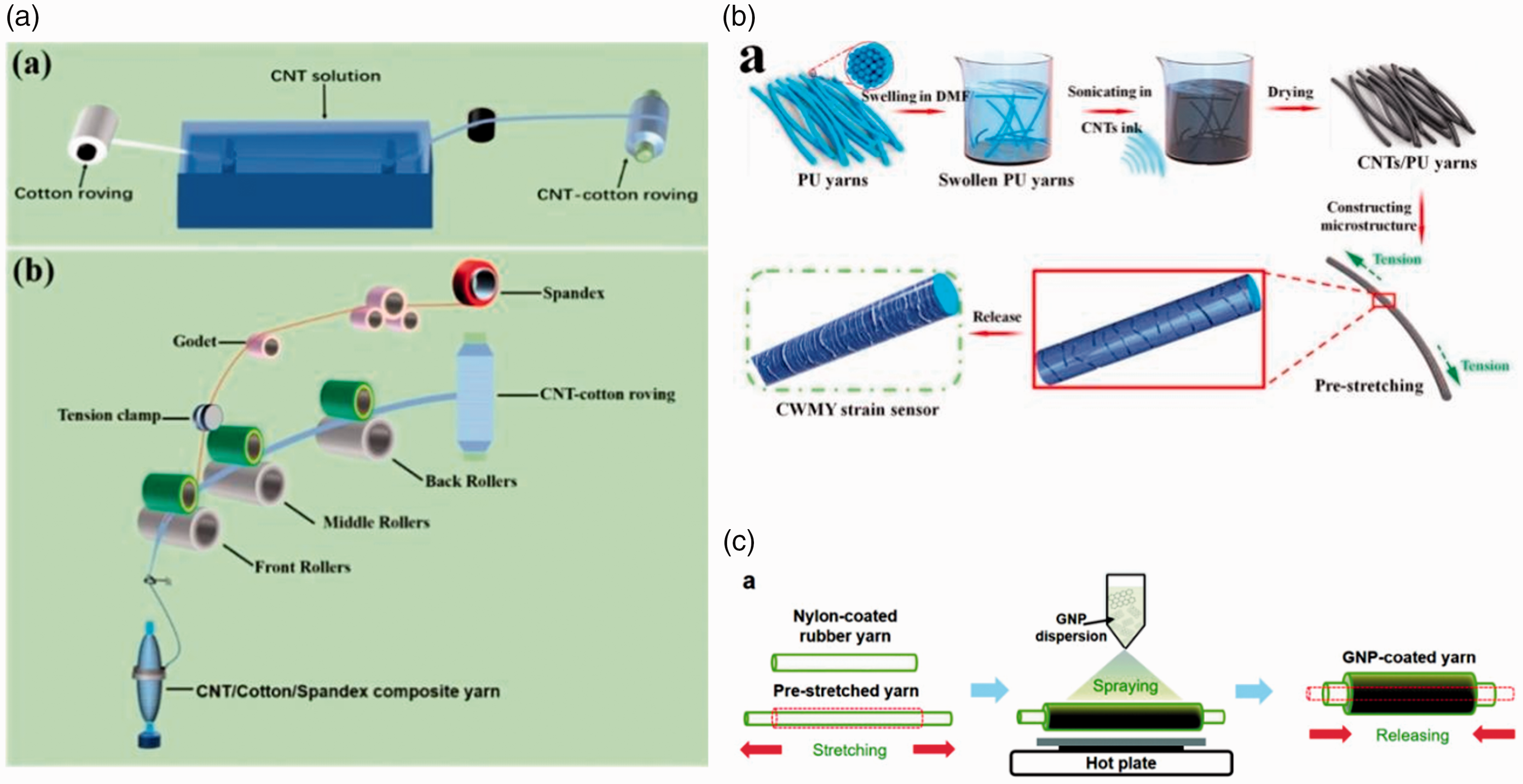
Fabrication of carbon-based yarn strain sensor (I). (a) Schematic illustrations of the preparation of carbon nanotube (CNT)/cotton roving and CNT/cotton/spandex composite yarn (CCSCY). 68 (b) Schematic diagram of production process of the wrinkle-assisted crack microstructure yarn strain sensor (WCMYSS). 69 and (c) Schematic illustration of the fabrication process for graphene yarn composite (GYC) strain sensor. 70
Graphene-based yarn strain sensors
Son et al. 70 proposed a flexible graphene-yarn strain sensor by spraying graphene nanoplates on nylon-coated rubber yarn instead of the dipping method, as shown in Figure 16(c). Compared with the dipping method, the spraying method not only exhibited 3.68 times higher conductivity, but also had 2.1 times higher stretchability. Furthermore, Zhao et al. 71 proposed a simple layered dipping and drying technology (Figure 17(b)). Spandex was used as the substrate, applying the principle of graphene nanoplatelets/polyaniline collaborative conductive network to prepare conductive yarns. By integrating the obtained strain sensor with the porous semipermeable membrane, a biocompatible, wearable and breathable electronic skin device was prepared.
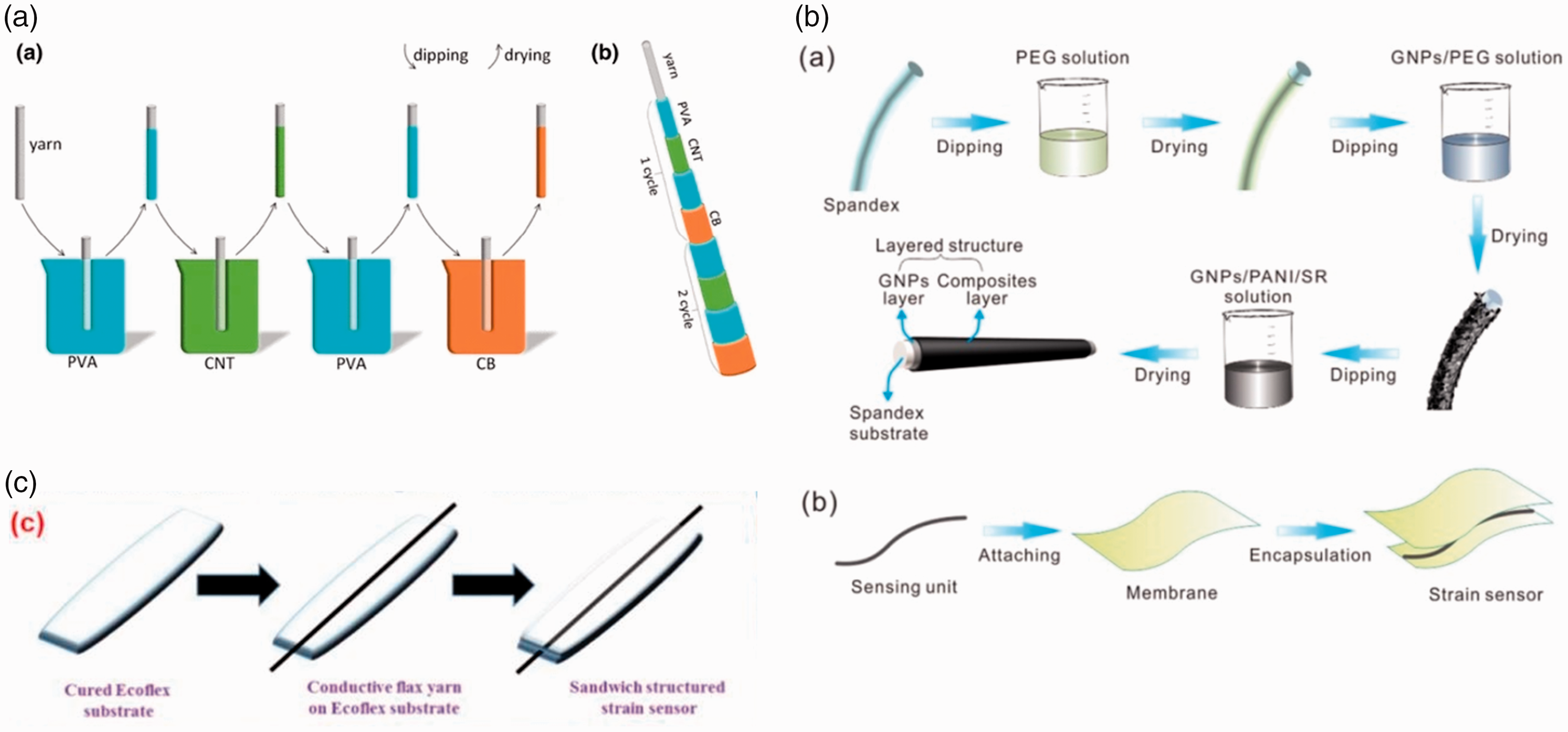
Fabrication of carbon-based yarn strain sensor (II). (a) Schematic illustration of the steps for fabrication of a carbon nanotube (CNT)/carbon black (CB) strain sensor using a stretchable yarn by the layer-by-layer (LBL) cycle. Each cycle of the process includes first polyvinyl alcohol (PVA), second CNTs, third PVA and last CB coating. 72 (b) Schematic diagram of preparation processes of fiber strain sensor with layered structure and fabrication of flexible and wearable electronic skin. 71 and (c) Schematic view of the fabrication process of the strain sensor. 73
CB-based yarn strain sensors
Due to the large aspect ratio of CNTs, flexible sensors made of CNT materials are less sensitive to small strains. In contrast, CB has a low aspect ratio, and its conductive network may undergo considerable changes under slight strain. Therefore, CNT and CB can be combined to improve the sensitivity of the strain sensor under small strain. Zhang et al. 72 developed a wearable flexible sensor manufactured by a LBL assembly method (Figure 17(a)). The yarn was coated with CNT and CB. Compared with the reported strain sensor, the sensor material was cheap and the manufacturing process was relatively simple. Souri et al. 73 first introduced a novel and effective coating technology to produce high-conductivity natural fiber yarns through ultrasound (Figure 17(c)).
Performance and mechanism of carbon-based yarn strain sensors
CNT-based yarn strain sensors
The introduction of CNTs into CCSCY contributed excellent electrical conductivity to CCSCY while the mechanical properties and stretchability were preserved. 68 It demonstrated that the CCSCY can be used as wearable strain sensors, exhibiting an ultra-high strain sensing range of 400% (Figure 18(a)), excellent stability, and good washing durability (Figure 18(b)). In addition, for the multiwalled CNTs ink/polyurethane yarn, 69 the designed structure originated from the mismatch in Young’s modulus and elasticity between the CNTs ink and polyurethane yarn during the stretching process. The structure endowed the sensor with the combined characteristics of high sensitivity towards stretching strain (GF of 1344.1 at 200% strain), an ultralow limit of detection (<0.1% strain), excellent durability (>10,000 cycles), a wide workable strain range (0–200%), and outstanding response and stability towards bending deformation (as shown in Figure 19(a) to (e)). The high-performance strain sensor improved performance across applications such as intelligent fabrics, electrical skins, and fatigue detection for full-range human motion monitoring. Detailed specifications of carbon-based yarn strain sensors are summarized in Table 4. It can be seen that cracks were an effective method to improve the sensitivity of the sensor, and the corrugated structure was an effective strategy to achieve a large strain range. When external force was applied, the wrinkled structure was flattened so as to adapt to larger strains and provide a stable electrical response during the stretching process. This provided a new idea for the design of the textile sensor structure.

Performance of carbon nanotube/cotton/spandex composite yarn (CCSCY) strain sensor. (a) Relative resistance change (ΔR/R0) as a function of strain for CCSCY and (b) Electrical resistance of CCSCF and carbon nanotube (CNT)-coated fabrics after repeated washing cycles.68
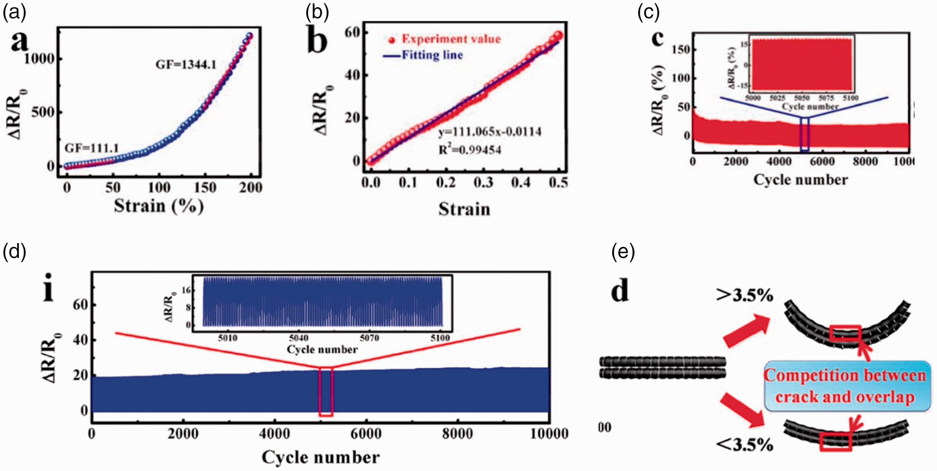
Performance and mechanism of WCMYSS strain sensor. (a) Relative resistance change (ΔR/R0) on the applied strains for WCMYSS after 100% strain prestretching. (b) Fitting line matches experimental value well when the strain was applied from 0% to 50%. (c) Long-term stability test of a WCMYSS for 10,000 bending–releasing cycles with chord lengths from 40 to 25 mm. (d) Long-term stability test of a WCMYSS for 10,000 stretching–releasing cycles towards the strain variation from 0% to 30% and (e) Schematic illustration of bending sensing mechanism of the wrinkle-assisted crack microstructure yarn strain sensor (WCMYSS). 69
Summary of performance of flexible yarn strain sensors
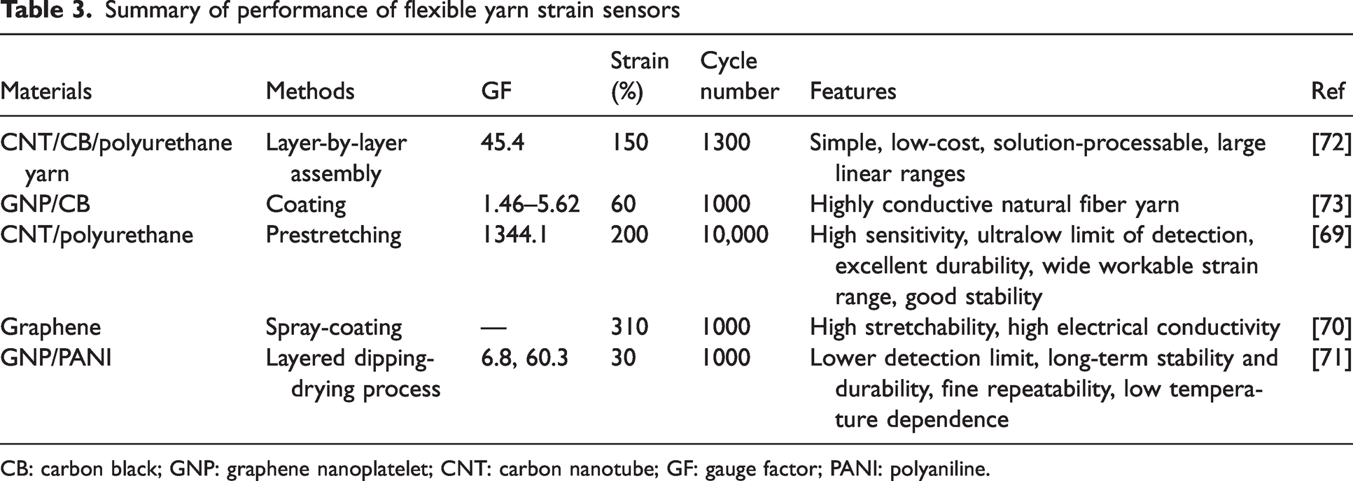
CB: carbon black; GNP: graphene nanoplatelet; CNT: carbon nanotube; GF: gauge factor; PANI: polyaniline.
Summary of performance of flexible yarn strain sensors
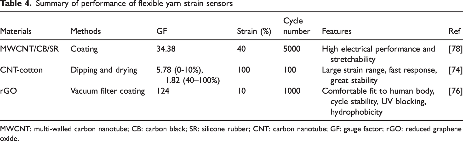
MWCNT: multi-walled carbon nanotube; CB: carbon black; SR: silicone rubber; CNT: carbon nanotube; GF: gauge factor; rGO: reduced graphene oxide.
Graphene-based yarn strain sensors
The graphene-yarn composite yarn strain sensor by spraying graphene nanoplates 400 times showed a high stretchability of 310%, as shown in Figure 20(a). 70 In addition, the manufactured sensor was coated with an ecoflex protective layer to minimize environmental impact. The passivated graphene-yarn composite sensor exhibited a higher resistance than the unpassivated sensor, but the response to strains up to 200% decreased after passivation (Figure 20(b)). The proposed spandex strain sensor with a layered structure showed a lower detection limit (0.2%) and high-sensitivity GFs calculated at 0–15% and 15–30% are ∼6.8 and ∼60.3, respectively. 71 It showed good durability, repeatability and low temperature dependence.

Performance and mechanism of graphene-based yarn strain sensor. (a) Relative resistance changes of graphene yarn composites (GYCs) with and without pre-stretching under tensile strain and (b) Relative resistance change of GYCs with and without Ecoflex coating under tensile strain. 70
CB-based yarn strain sensors
The yarn strain sensor coated together with CNT and CB showed high sensitivity (GF up to 45.4), 150% stretchability and excellent linearity (Figure 21(a) and (b)). 72 In addition, when the novel and effective coating technology was introduced to natural fiber yarns, the strain sensor exhibited good sensitivity, and its GF was in the range of 1.46 to 5.62, showing up to 60% of the strain energy electromechanical response. 73

Performance and mechanism of carbon black (CB)-based yarn strain sensor. (a) Under varying layer-by-layer (LBL) numbers, the relationship between the relative resistance changes of the carbon nanotube (CNT)/CB stain sensors and the strains and (b) The illustration of the linear response of the strain sensor when the number of the conductive layers was 10. 72
Carbon-based fabric strain sensors
Based on the yarn strain sensor, various fabric strain sensors were manufactured. A flexible fabric sensor used textiles as a substrate and combined them with sensing materials or components in different ways to meet the needs of various wearable devices. The conductive fabric or other textile types integrated the wearing performance and smart sensing function. The additional value greatly promoted the smart wearable applications.
Fabrication of carbon-based fabric strain sensors
The preparation methods include the coating method and inlaid weaving method. In the coating method, the polymer conductive polymer material is processed on the surface of fabric in the form of printing, printing or collage. The inlay method is directly to knit the conductive yarn into a flexible sensor device based on a strain-sensitive knitted structure. There are two ways to form the conductive yarn. One method is to plate the surface of ordinary yarn with conductive carbon material. The other way is to compound the yarn with conductive properties and functional yarn. It should be noted that the sensor obtained by the coating method has better sensitivity and linearity, while the interlaced method has better deformation, durability and a larger measurement range.
Yang et al. 74 prepared one conductive cotton fabric by coating SWCNT on the surface of knitted cotton fabric through the ‘soak-drying’ method. Liu et al. 75 fabricated fabric sensors by embedding CNT-based strain sensing yarns into woven structures. Wang et al. 76 proposed a simple strategy to fabricate graphene–silk fabric strain sensors as shown in Figure 22(b). Among them, GO was coated on the silk fabric by vacuum filtration and reduced by an environmentally friendly hot-pressing method. You et al. 77 used simple and low-cost electrospinning technology to construct a highly sensitive and stretchable electronic fabric. The sensor allowed the simultaneous mapping and quantified the mechanical stress caused by normal pressure, transverse strain and bending. The fabric was manufactured from composite yarn, which was formed by spirally winding a core-spun yarn on the surface of an elastic thread. Core-spun yarn was coated with GO-doped polyurethane nanofibers obtained on rayon (Figure 22(a)).

Fabrication of carbon nanotube (CNT)-based fabric strain sensor. (a) Schematic illustration of the fabrication processes of the electronic fabric with a capacitive sensor unit. 77 (b) Preparation of a graphene-coated silk fabric. 76 and (c) Blade-coating processes of multi-walled carbon nanotube (MWCNT)/carbon black (CB)/silicone rubber (SR) composites. 78
Performance and mechanism of carbon-based fabric strain sensors
Strain sensors made of CNT–cotton fabric show a large working strain range (0∼100%), rapid response and excellent stability. 74 CNT coating on the conductive cotton fabric improved its mechanical properties and gave the fabric conductivity. In addition, CNT–cotton fabric also exhibited a strong electric heating effect. When the CNT-based strain sensing yarns were embedded into woven structures, higher mechanical properties were achieved by coating PVA on the yarn. 75 Yarn GF exceeded 1.1 from 0.91 increased to 1.64. The linearity exceeded 97%, indicating good stability and repeatability during cyclic loading. In addition, fabrics with different integrated yarn lengths, styles and output connections have also been studied. The results showed that integrated yarn length and bending had a great influence on the strain sensing performance of the fabric.
Compared with coating CNT on the yarn surface or embedding conductive yarn into fabric, the integrated weaving method should be a more effective way to develop fabric sensors. For example, the graphene–silk fabric strain sensors showed excellent performance. 76 They exhibited a wide range of strain (about 10%), excellent sensitivity or GF (about 124), good linearity, cycle stability, and comfort to the human body. In addition, it was also found that the sensitivity of the silk fabric strain sensor changed with the angle of the fabric during stretching. The obtained sensor also showed anti-ultraviolet and hydrophobicity resulting in a versatility feature of the textile strain sensor. In addition, the electrospinning electronic fabric developed by You et al. 77 showed good stretchability and a wide strain sensing range (up to 100%), short response time (<50 ms), good cycle stability and repeatability. It was suitable for voice recognition, noncontact airflow monitoring, finger and wrist muscle movement, etc. The fabric sensor proposed by Li et al. 78 provided a common platform for the integration of other stretchable elastic materials and promoted the future development of smart clothing manufacture. The sensor GF was up to 34.38. After the sensor was immersed in water for 10 days or stirred at room temperature for 8 h, the fabric sensor could also operate normally.
The characteristics of carbon-based flexible sensors are compared and listed in Table 5. Carbon-based strain sensors are prepared by various methods, thin film sensors are prepared by wet, dry, CVD, mixed with polymers. Nanotextile technology has created conditions for the preparation of high-performance fiber strain sensors. Simple coating methods combined with yarn textile structures make it possible to have strain sensors with high sensitivity and large strain range at the same time. Easy integration into garments makes the research of fabric strain sensors promising.
Comparison of carbon-based strain sensors of four different assembly structures

CNT: carbon nanotube; CB: carbon black; CVD: chemical vapor deposition.
Challenges and prospects
With the rapid development and huge demand for wearable electronic devices, flexible and stretchable sensors need to solve scientific problems such as new sensing principles, complex environmental analysis and multifunctional integration, as well as technological breakthroughs in preparation processes, material synthesis and device integration.
Current strain sensors with large strain range and high sensitivity are inadequate. New materials and signal sensing mechanisms need to be proposed to prepare sensors with high sensitivity, stability, reliability and wide sensing range. Sensors need to be versatile and able to collect multiple signals simultaneously. There is an urgent need to integrate and assemble multiple sensors into one textile product. It requires more research on sensor integration, including signal acquisition, sensor interface, signal processing unit, and signal storage sections. It is essential to develop the route to use wearable sensors based on carbon and textiles in the future in health monitoring. In addition, the compatibility of textile sensors with traditional textile manufacturing processes needs to be considered to achieve scalable and low-cost sensor mass production in the future. More attention should be paid to practical applications to ensure the safety, comfort and shape retention of future devices on the human body or clothing.
Conclusions
A comprehensive evaluation of the carbon-based nanocomposite flexible strain sensor was reviewed and discussed. Preparation methods and sensing performance of various carbon-based sensors such as CNTs, graphene, and CB have been analyzed and compared. CNTs and graphene exhibited conductivity properties while the CB was cheap and easy to obtain. These conductive materials can be made into various structures in smart wearable textiles, such as films, fibers, yarns and fabrics. The film flexible sensor was the initial type while the fiber, yarns and fabric sensors can be better used in clothing or other textiles. The sensitivity and strain range of textile-based strain sensors are comparable to film strain sensors, while the stability, durability and ease of integration into garments have been improved. Therefore, textile-based strain sensors have greater prospects for development in the field of smart textiles. Investigation showed that flexible strain sensors based on carbon nanomaterials have low cost, high sensitivity, stretchability and stability. In addition, results showed that the structure, dispersion and preparation process of conductive nanomaterials have a significant influence on the performance of strain sensors. Crack growth was considered to be the main influence on sensing performance. Last but not least, some suggestions and prospects have been proposed for the flexible textile-based sensors in the future.
Footnotes
Declaration of conflicting interests
The author(s) declared no potential conflicts of interest with respect to the research, authorship, and/or publication of this article.
Funding
The author(s) disclosed receipt of the following financial support for the research, authorship, and/or publication of this article: The author(s) acknowledge the financial support from the National Natural Science Foundation of China (Grant No. 11802192), Natural Science Foundation of Jiangsu Province (BK20180244), Jiangsu Students' innovation and entrepreneurship training program (2021suda036) and the financial supports from QingLan Project.
Funding
The author(s) acknowledge the financial support from the the National Natural Science Foundation of China (Grant Number 11802192), and Natural Science Foundation of Jiangsu Province (BK20180244).The financial supports from Jiangsu Students' innovation and entrepreneurship training program (2021suda036). The financial supports from QingLan Project.
