
Abstract
The application of high speed air flow in the textile field represents the frontier development direction in this field. However, the coupling mechanism between air flow and fiber is extremely complicated which greatly limits the development and application of new textile technologies. For this reason, this research study is intended to focus on the common cutting-edge basic scientific problem of the air-flow-fiber coupling mechanism, the vortex spinning technology is taken as a breakthrough point for research. Three-dimensional numerical models of air flow in vortex spinning nozzle and a free-end fiber were established. The hybrid grids including the structured hexahedral grids and the unstructured tetrahedral grids were used to divide the air-flow computational region, the realizable κ-ε model was used to solve the turbulent characteristics of air flow, and the wall function method was used to solve the air flow in the near wall region. The displacement and deformation of a single free-end fiber under the action of the air-flow force was solved by the second-order nonlinear double asymptotic method and interpolation method. The dynamic twist process of a free-end fiber was simulated in three-dimensional space by taking into account the fiber characteristics, such as straightening, bending, and torsion. In addition, a high magnification microscope was used to observe the free-end fiber motion during the spinning process. The results show that the numerical simulation is consistent with the experimental observation, proving that dynamic numerical simulation can solve difficult problems in the unobserved dynamic twisting process, and this deepens the understanding of the spinning mechanism in vortex spinning.
Keywords
In vortex spinning, when the front end of a fiber is located in the yarn center and the trailing end of the fiber is clamped by the front rollers, both ends of the fiber are well restrained, and the influence of air flow on them is relatively small. When the fiber ends are separated from the front rollers, some of the fiber ends will be separated from the fiber bundle under the action of air flow and they will become free-end fibers. The free-end fibers will fall back on the cone body’s surface in the shape of an umbrella and then will be twisted around the yarn by the air flow. The leading fiber ends enter into the center of the yarn body to form the core, and the trailing fiber ends are wrapped around the outside of the yarn body to form outer wrapping fibers, forming a special skin-core structure. This special structure makes the yarn stronger than air-jet spun yarns, with higher breaking strength and better evenness; in addition, during the spinning process, most of the short fibers are blown away by the air flow.1,2 It is the fiber motion in the nozzle with the air flow that forms a special structure of the vortex yarn, therefore, the motion characteristics of the fiber under the action of air flow are critical to the yarn structure.
Due to the complexity of the internal structure of the vortex spinning nozzle and the fiber motion, many scholars3–6 have simplified the theoretical model in various aspects to facilitate research. Most of them7–9 used computational fluid dynamics (CFD) software to build two-dimensional (2D) or three-dimensional (3D) models to simulate the air-flow field within the nozzle, and examined the change of the air-flow field with different nozzle parameters and the influence of air-flow field on the fiber motion.10–13 Since the twisting process of vortex spinning is the separation and condensation of free-end fibers in 3D space, 3D simulation is closer to reality than 2D simulation. In terms of experimental verification, the most basic method is the spinning experiment, which provides information on yarn quality under different nozzle structures and spinning parameters. Other experimental methods have also been used to verify the simulation results and theoretical analysis. Pei et al. 14 observed the characteristics of fiber motion in the nozzle by means of high speed camera. Sun et al. 15 used particle image velocimetry (PIV) to observe the change of air-flow field with different nozzle parameters. Wang et al. 16 used tracer fiber observation technology to observe the yarn quality with different nozzle parameters. Infrared photography technology,17,18 the laser doppler velocimeter (LDA),19,20 and PIV 21 have also been used to study the air-flow field in the Murata Jet Spinning (MJS) and Murata Vortex Spinning (MVS) nozzles, and to analyze the effect of relevant parameters on the air-flow field distribution in the nozzles. These auxiliary experimental observation methods are very helpful for verifying the numerical simulation results and understanding the spinning process.
In summary, most of the established fiber models are 2D, and the simulation result is an approximate solution; however, the motion of the fiber inside the nozzle is 3D, and the 2D fiber model fails to consider the fiber motion and deformation in the real 3D space. Therefore, the establishment of a 3D fiber model and its numerical simulation and experimental analysis will allow more realistic understanding of the fiber motion. The separation and agglomeration process of fthe fiber bundle under the action of high speed swirling air flow affects the twisting wrapping effect of the yarn and ultimately determines the morphology and structure of the yarn; the interaction and deformation of fibers under high speed swirling air flow affects the binding force and friction force of the fibers within the yarn and ultimately determines the strength of the yarn. At present, there is little research on the dynamic evolution process of fiber wrapping by air flow, and experimental methods do not allow accurate direct observation. It will be of great benefit to the optimization of the spinning process if the dynamic evolution process of fiber wrapping can be obtained through simulation.
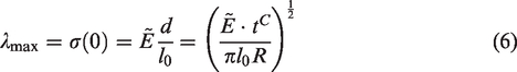
The effect of high speed swirling air flow on the fibers is completed within a very short time, usually in the range of milliseconds or less. In addition, the fiber itself is a extremely small and soft elastic body with great length to diameter ratio, about 38 mm in length and 15–20 microns in diameter, so it cannot show up at all in the air-flow field (the maximum size of the air-flow field is about 5 cm) numerical analysis images. Thus, these extremely small fibers need to be separated from the air-flow field for research and analysis. In our previous results, 22 we looked not only at the unsteady air flow (including the velocity field, the turbulent kinetic energy, and the trajectory of the air flow, etc.), but also at the influence of air flow on fiber, the important air-flow fields that affect the fiber were analyzed already in a previous research study. 22 In this article, we provide details of a continuation of previous research, and our main focus is on the characteristics and motion of the fiber.
In this study, 3D modeling of a single free-end fiber was carried out, the motion trajectory in 3D space of a free-end fiber was simulated in vortex spinning nozzle. The motion of the fiber in spinning experiment was observed with a high-magnification microscope to verify the dynamic numerical model. The movement and deformation of the free-end fiber in 3D air-flow field were revealed; the twisting and wrapping mechanism of the free-end fiber on the yarn body were clarified. These details deepen the understanding of the spinning mechanism and help establish the control of special yarn structures using vortex spinning.
Numerical modelling
Computational model
Computational model of air-flow region in the nozzle
The diagram of the nozzle and related components used in this research is shown in Figure 1, the blue marked region is the air-flow area inside the nozzle. The nozzle is mainly composed of four parts: 1 – the guiding body; 2 – the vortex tube; 3 – the cone body; 4 – the doffing tube. The role of the guiding body is to gather and lead the fiber bundle; the vortex tube is a main twisting part of the nozzle, the fibers are twisted inside the twisting chamber which is inside in the vortex tube; the cone body supports the fiber ends in the twisting process; the doffing tube’s function is to draw the fibers into the twisting chamber as well as to lead and output the resultant yarn. 7 The 3D computational model of air-flow area is illustrated in Figure 2. The internal structure of vortex tube in this research has three stages, the air jet orifices on vortex tube is drilled on the connecting edges of the first and second stages, which provide sufficient space to stabilize the air-flow rotation. The diameter of the second stage where the air holes of the vortex tube are located is larger than that of the first stage, so the air flow has no tendency to flow back to the first stage, preventing backflow. The parameters of the main nozzle structure in this research are set as: the angle of spiral surface of guiding body: 35°, the length of guiding needle: 1.5 mm; the number, diameter, and angle to the Z axis of jet orifices on the vortex tube: 5, 0.5 mm, and 60°, respectively; the tip angle and the inlet diameter of the cone body: 10° and 1.5 mm, respectively; the number, diameter, and angle to the Z axis of jet orifices on the doffing tube: 5, 0.4 mm, and 45°, respectively. In Figure 2, the Cartesian coordinate system is defined as: Z axis represents yarn output direction, X axis represents radial direction, and Y axis represents tangential direction.
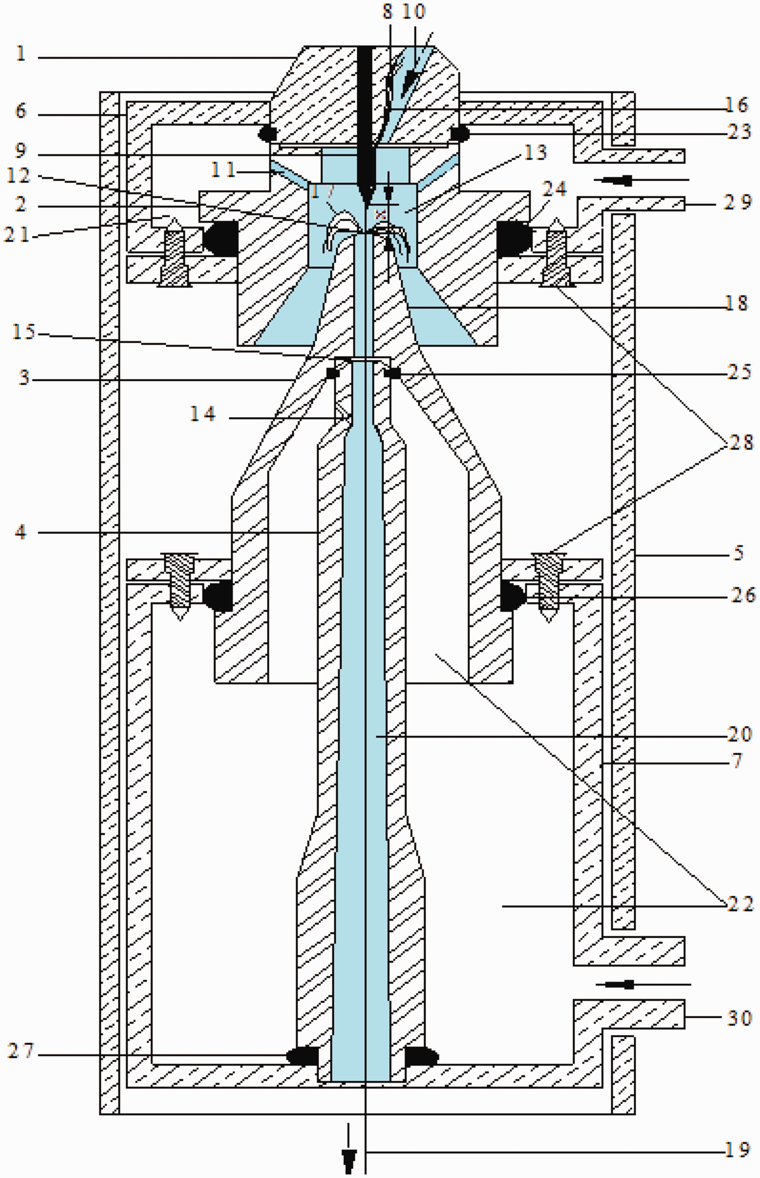
The view of vortex spinning nozzle and its main components (the blue area is the air-flow area).
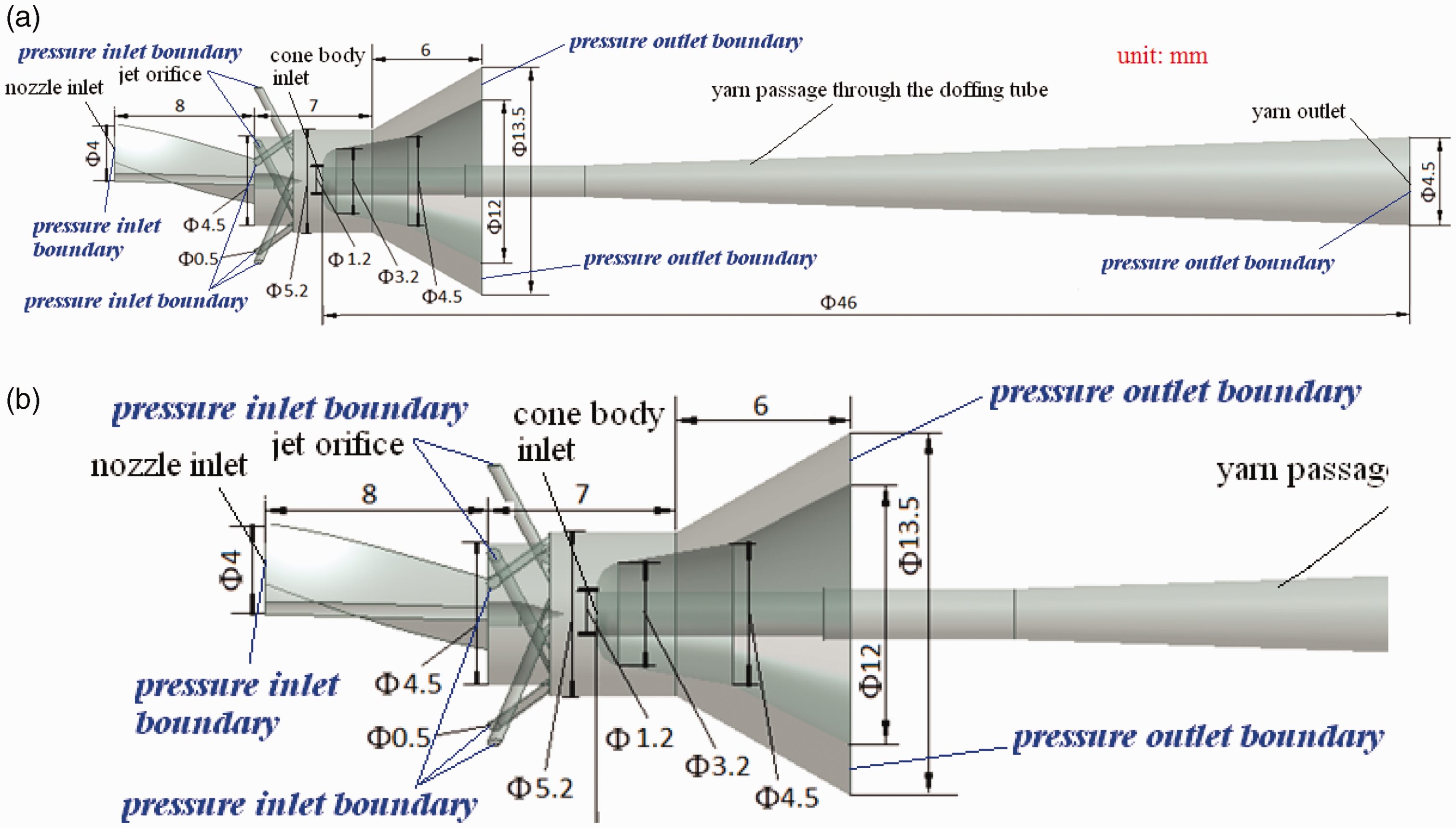
Three-dimensional computational model and its dimensions of air-flow area inside the nozzle. (a) Frontal view of the simulated calculation area and (b) A partial enlarged view of the simulated calculation area.
Fiber modelling
As shown in Figure 3 and Figure 4, the fiber is simulated as a cylinder with a large length to diameter ratio and is dispersed into multiple interconnected and non-overlapping prismoids. In this model: when the fiber is not subjected to external forces, it is described as a cylinder, as shown in Figure 3(a), the cylinder length direction is the fiber’s length direction, and the radial direction of the cylinder represents the fiber radial direction. The radial and circumferential directions of the cross sections of the fiber were discretized into segments of equal length, as shown in Figure 3(b). The fiber is discretized into small segments of equal length along the direction of length, and the topological structure of the fiber section after discretization is projected along the direction of fiber length, then the entire fiber body is discretized into multiple interconnected prismoids that do not overlap with each other, as shown in Figure 3(c). The prismoids are divided into two shapes, one is a pointed triangular pentahedron (with six nodes) near the core fiber, as shown in Figure 3(d), and the other is a curved trapezoidal hexahedron (with eight nodes), as shown in Figure 3(e). The vertices of each prismoid grid are called “nodes,” the force on the fiber body is assumed to be acting on the nodes of prismoid elements. The pointed triangular pentahedron and the curved trapezoidal hexahedron have six and eight nodes respectively. The nodes of the element have six degrees of freedom, including three rotational degrees of freedom (x, y, z) and three translational degrees of freedom (ζ, η, δ), as shown in Figure 4(d). In the simulation, the impact force of the high speed air flow exerted by the flow on each prismatic element can be expressed by the shape function vector and the nodal pressure vector. Due to the bending, torsional, and winding movements of flexible fibers in 3D space under the impact of high speed swirling air flow, it is necessary to convert Cartesian coordinates to spatial curvilinear coordinates continuously during the simulation calculation, that is, the mutual physical transport of node pressure vector and shape function vector is used to solve the force and deformation of each node. Then the fiber body’s displacement, stress, and strain are solved in each element, and the solution of corresponding parameters on a whole fiber can be obtained by combining the solutions of all elements. The tensile, bending, and torsional deformations produced by the fiber model are shown in Figure 4(a)–(c), respectively.

Three-dimensional flexible fiber models.

Straighten, bend, and torsion deformations of the fiber model.
Fiber/wall surface contact model
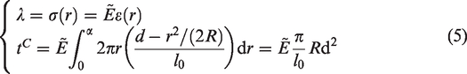
The fiber/wall interface is a soft body/rigid body contact, and the fiber/fiber interface is a soft body/soft body contact. The Hertz contact theory is used in this study. It is assumed that the object in contact can be regarded as an elastic half-space body, and only distributed vertical pressure is applied on the contact surface. The contact surface is elliptic, and a small deformation occurs in the contact area. It is assumed that the maximum thickness of the bump after the fiber contacts the wall surface is l0, and the radius of curvature is R. The contact radius is defined as a, and the depth of compression (radial deformation of fiber) is d. It is assumed that in the contact area, the displacement meets: d ≪ l0, for the deformation, the modulus

At the position close to the contact center:
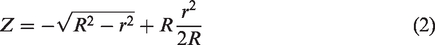
According to Figure 5, the relation between the contact radius a and the pressing depth d is


Fiber and wall surface in contact (observed in radial direction).
Along the coordinate axis r, the vertical displacement of the convex surface of the sphere is

The equation of normal stress
The maximum normal stress
Governing equations
Governing equations of air-flow field
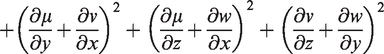
In the process of vortex spinning, the compressed air is injected into the twisting chamber through tangentially configured air holes on the vortex tube in the nozzle to form a high speed swirling air flow. The mass conservation equation, the momentum conservation equation, and the energy conservation equation are used to solve the air-flow field numerically; the realizable κ-ε model is adopted in this study as a computational method of turbulence; the wall function method is adopted to solve the air-flow field numerically in the near wall area. The governing equations are:


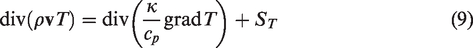
In the above equations, ρ represents air density;
Realizable κ-ε model’s transport equations are as follows:
κ – transport equation:

ε – transport equation:


In the above equations, κ represents the turbulence kinetic energy (m2/s2); ε represents the turbulence kinetic energy dissipation rate (m2/s3); Cµ represents coefficient, it is not a constant in this study, but a coefficient related to the Reynolds number;
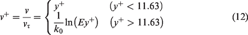
In the vortex spinning nozzle, the near-wall area of the nozzle’s inner wall where the air flows through has a great effect on the overall air flow, and the Reynolds number in this area is lower than that in the core area. Therefore, for the solution of the contact between air flow and nozzle inner wall surface, the wall function method can be used for a supplementary solution. The wall function method is a set of semi-empirical formulas, which are utilized to connect the physical quantity on the nozzle wall surface with the corresponding physical quantity in the turbulent core.
23
For each transport equation, the formula connecting the nozzle wall surface value and the node value in the core area are given:
The boundary condition of turbulent kinetic energy κ on the wall surface is:
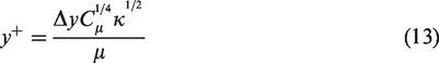
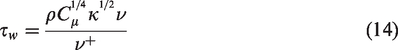
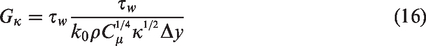
The expression for the turbulent kinetic energy generation term Gκ (constituted from the source term of κ equation) and the turbulence dissipation rate ε are calculated as follows:
Fiber structure discrete solution equation
The basic conditions applied to the air-fiber coupling interface are kinematic conditions (displacement coordination) and dynamic conditions (force balance). The velocity of air flow is obtained by kinematic conditions, and the force of fiber is obtained by dynamic conditions. According to the kinematic conditions, the position of the air-flow nodes on the air-fiber interface is determined by the displacement, in this article, the condition of no slip wall surface is adopted, the air-flow velocity is thus supposed to equal to the displacement of air-flow particles. The displacement of other nodes is automatically determined by the calculation program to retain the mass of the initial grid. According to the dynamic conditions, at the fluid-structure interface, the distribution force of the air flow is applied to the fiber node by the concentrated force generated by the integral form. That is, the displacement of the air-flow node is obtained by the displacement interpolation of the fiber node, and the displacement of other fluid nodes is calculated by the calculation program. Similarly, the force exerted by the air flow on the fiber nodes is obtained by interpolating the stress of the elements on the fluid boundary around the fiber nodes. The second order nonlinear double asymptotic method is adopted to solve the fiber motion characteristics in the air-flow field of the nozzle, the basic governing equations are as follows:


In the above equations,
The simultaneous solution of equations (18), (19), (20), and (21) is called the second-order nonlinear double asymptotic method. Triangular element interpolation method is used to solve the fiber structure discretely, the solution idea is as follows:
Boundary conditions
The boundaries and their dimensions are as shown in Figure 2. For the pressure inlet boundary; the pressure of the five jet orifice inlets is set at 0.6 Mpa; the pressure of the nozzle inlet is set equal to atmospheric pressure. For the pressure outlet boundary; the pressures of doffing tube and cone body are set equal to atmospheric pressure. For the wall surface boundary; the wall surface boundary follows the no-slip boundary condition.
Computational grid
Grid generation for air-flow field area
In the vortex spinning process, the high speed swirling air flow is sucked into the nozzle and collides with wall surface; the fiber movement is caused by the air flow, then the fiber contacts or collides with the wall surface. In this process, the fibers generate large nonlinear deformation with tensile, bending, and torsion because of the effect of the air flow; in turn, the swirling air flow is disturbed by the wall surface and the fiber motion. The interaction between the air flow and the fibers is complex and dynamic, and the boundary conditions are constantly changing, thus the shape of the air-flow field is constantly changing. Therefore, there is a complex fluid-solid coupled interaction between the fibers and the air flow. However, the dynamic grid model can resolve the dynamic shape of the air-flow field.
Due to the complex structure of vortex spinning nozzle, the small space of the twisting chamber inside the nozzle and the extremely large length to diameter ratio of the fiber, the grid generation and simulation calculations are time consuming. In order to improve the accuracy of numerical simulation, one method is to increase the number of grids, and the other method is to use more accurate grids. The precision of a hexahedral grid is much higher than that of a tetrahedral grid, but local densification of tetrahedral grids is easier to achieve, which is particularly important for capturing locations with high stress gradients (such as the air jet orifices and the guided needle). For complex structures, using a tetrahedral grid with low precision but large number of grids is simpler to construct.24,25 Therefore, in order to improve the solution accuracy and comprehensively assess the grid generation time and the simulation calculation time, the air-flow region is partitioned based on the idea of grid partitioning. 26 In this article, the integrated computer engineering and manufacturing (ICEM)-CFD module in ANSYS is used to divide the air-flow area in the nozzle into five parts, and then each part is divided into grids. The hybrid grids including the structured hexahedral grids and the unstructured tetrahedral grids are used, as shown in Figure 6. The interface between the two grids is constrained by binding, and the dynamic grid technology is used to conduct the simulation. In order to improve the accuracy and reliability of simulation results, the air jet orifices and the complex structures of the nozzle are processed with grid refinement.

Grid division of air-flow field area inside the nozzle. (a) A front view of air-flow field grids; (b) a top view of air-flow field grids; (c) a sectional view of air-flow field grids and (d) a partial enlarged sectional view of air-flow field grids: H1 = 5.2 mm, H2 = 1.9 mm, H3 = 1.4 mm, H4 = 1.2 mm, H5 = 0.3 mm.
The 3D front view and top view of the air-flow field region grid are shown in Figure 6(a) and (b), respectively; a sectional view of the grids is shown in Figure 6(c); and a partial enlarged sectional view of the grids is shown in Figure 6(d) which has five grid regions: the entire air-flow field region is divided into five grid regions: (a) zone 1: the region of air-flow field at the nozzle inlet (structured hexahedral grids); (b) zone 2: the region where the nozzle inlet is connected with the air jet orifices of the vortex tube (structured hexahedral grids); (c) zone 3: the region near the air jet orifices of the vortex tube (unstructured tetrahedral grids with local grid refinement areas which are at the air jet orifices and guided needle); (d) zone 4: the region of the twisting chamber (unstructured tetrahedral grids without local grid refinement): in zone 4, there is the entrance of the cone body, as described above, after passing through this zone, the free-end fiber affected by the swirling air flow will produce a certain angular displacement on the inner fiber along with the motion of the fiber bundle and then will wind around the outer part of the yarn to finish twisting. In the simulation calculation, the presence and movement of fibers will affect the air flow, making the shape of the air-flow field constantly change, there are complex interfaces between fibers and air flow. If only the high-precision hexahedral grid is used for grid division, the effect of air flow on the fiber and the reaction of the fiber on air flow will cause large deformation of the grid in the simulation calculation process, resulting in the non-convergence of the 3D transient air-flow field. In addition, due to the complex internal structure of each nozzle component, it is difficult to divide the whole air-flow region into a fixed shape grid. Therefore, in order to improve the solution accuracy and balance the grid division time and simulation calculation time comprehensively, the unstructured tetrahedral grids without local grid refinement were selected to implement grid partitioning; (d) zone 5: the region of doffing tube (structured hexahedral grids). The grids are refined at air jet orifices on the vortex tube and guiding needle. Hierarchical grids are adopted near the narrow regions and the boundary layer, and 1,790,510 grids, as shown in Figure 6, are adopted in this study.
Grid generation of free-end fiber
At present, due to the large number and small size of the fibers, the computer speed is limited during simulation. In order to fully show the twisting process of the free-end fiber and to reduce the computational load and speed up the convergence, a single free-end fiber is numerically simulated in this study. The fiber end separated by the air flow is simulated. At this moment, the leading fiber end is held by the fiber bundle and fixed in the yarn body; the fiber end moves with the high speed swirling air flow. Therefore, the object simulated is a very small part of the tail of the free-end fiber segment separated by the action of high speed swirling air flow, as shown in Figure 7(a). The left end of a free-end fiber is its tail end and the right end is its head end which is held in the yarn body.

Single free-end fiber motion by numerical simulation at different times. (a) t = 0 ms; (b) t = 0.05 ms; (c) t = 0.1 ms; (d) t = 0.15 ms; (e) t = 0.2 ms; (f) t = 0.25 ms (g) t = 0.3 ms; (h) t = 0.35 ms; (i) t = 0.4 ms; (j) t = 0.45 ms and (k) t = 0.5 ms.
In this article, to simplify the simulation, viscose fiber is used as an example. The fiber parameters are: length: 5 mm, density: 1.50 g/cm3, breaking strength: 20 cN/tex, fiber fineness: 1.3 dtex (about 15 µm in diameter), breaking elongation: 15%, elastic modulus: 43.1 cN/dtex, relative bending stiffness: 3 × 10⁻⁴ cN · cm2/tex 2 , relative torsional stiffness: 4.5 × 10⁻⁴ cN cm2/tex 2 . The mechanical model of a single free-end fiber is shown in Figure 3 and Figure 4. The transient structural module in ANSYS is used for generating the grid of the 5 mm tail segment of the fiber, and unstructured rectangular blocks are used to divide the fiber models in Figure 3 and Figure 4, and the number of divided grids is 2880.
If the time step is too large, the calculation will diverge, and if the time step is too small, the calculation time will be greatly increased. The internal grid nodes of the air-flow area in the nozzle are obtained by recreating the grid nodes. For these grid nodes, the corresponding flow field parameters at the previous time need to be obtained. For example, when the current grid is located at the time n + 1, the corresponding flow field parameters of these new nodes at the time n and n − 1 are needed to finally solve the problem of fiber motion under the action of unsteady flow field. However, this time segment becomes difficult to be determined because of the addition of fiber motion. Based on the time step set in the study of Guo, 10 in order to accelerate convergence in this study, the appropriate time step was selected based on the maximum grid size and minimum fiber rotational speed, and the period of unsteady phenomenon, grid deformation amplitude, convergence condition were considered comprehensively. Finally, the time step of the fiber motion equation was set as 0.05 ms in this research study.
Results and discussion
The causes of fiber motion: in the vortex spinning process, the swirling air flow is disturbed by the existence of the fibers and the fiber motion which results in the redistribution of high speed swirling air-flow field within the nozzle, in turn, the fibers generate nonlinear large deformation with straightening, bending, and twisting because of the effect of the air flow. Therefore, there is a complex fluid-solid coupled interaction between the air flow and the fibers which is the basis of the research on vortex spinning. From Figure 1 and Figure 2, the tip end of the cone body extends into the twisting chamber, and the air flow ejected from the air jet orifices collides with it to generate a winding air flow around it, after passing through the entrance section of the cone body, the free-end fiber affected by the swirling air flow will produce a certain angular displacement on the inner fiber along with the motion of the fiber bundle and then will wind around the outer part of the yarn to finish twisting. Under the action of high speed swirling air flow, a twisting cycle of the free-end fiber will be completed which is usually a period of 0.80 ms or less. After removing the time for the free-end fiber to separate from the yarn body and lodge in the cone body, the time scale of the fiber motion will be much shorter. 10 Therefore, 0.50 ms was selected as a motion cycle for simulation analysis in this article. As previously mentioned, t = 0.05 ms was taken as the time step length, and 11 instantaneous moments between t = 0 ms and t = 0.50 ms were taken for simulation analysis, and the motion of other free end fibers is similar.
The motion of a single free-end fiber at different moments is shown in Figure 7(a)–(k). As can be seen from Figure 7, on the whole, when the free-end fiber moves with the high speed swirling air flow, it undergoes a large displacement and bending, a relatively small torsion, but almost no elongation. When t = 0 s to t = 0.15 ms, the fiber motion changes little, as shown in Figure 7(a)–(d). After passing through the spiral guide channel of the guiding body, the fiber end begins to be separated from the main fiber bundle and becomes a free-end fiber which moves with the air flow. In addition, the dynamic pressure near the wall surface helps to drive the air flow continuously moving forward, thereby facilitating the withdrawal of the tail-ends of the partial fibers from the yarn body to form more free-end fibers, and facilitating the movement of the free-end fibers. The air flow is accelerated continuously in the air jet orifices of the vortex tube and reaches its maximum value at the air jet orifices outlet. Therefore, the tail of free-end fiber is also accelerated with the air flow, and the free-end fiber is in a state of tension with small deformation, as shown in Figure 7(a)–(d).
With the increase of time, when t = 0.2 ms to t = 0.3 ms, the motion of the single free-end fiber begins to produce a certain degree of bending. In the uncut-through connected region (the region where the twisting chamber is not connected directly with the spiral guiding channel), only the tail-end is connected with the atmosphere, the head end is the inner wall of the nozzle. The collision probability of air flow is increased due to the existence of fiber and cone body in the central area of the twisting area; coupled with the effects of air-flow confluence, circumfluence, collision, and counter air flow, etc., the air flow in the nozzle is disturbed, resulting in continuous turbulence. The fiber head which is near the main part of the fiber bundle, moves gradually towards the upstream near the wall surface zone and the countercurrent zone where the air stream impinge under the action of high speed swirling air flow. The head of the free-end fiber has a weak s-shaped movement because of the difference in air-flow velocity caused by adverse currents, as shown in Figure 7(e)–(g).
Then, from t = 0.35 ms to t = 0.4 ms, the movement of the free-end fiber gradually produces a large degree of s-shaped torsion, as shown in Figure 7(h)–(i) with the light blue area at the end of the fiber. The weak s-shaped motion at the fiber head is transmitted to the fiber tail under the action of air flow. Since the fiber tail is separated from the fiber bundle body and then falls on the tip of the cone body surface under the action of the air flow’s axial force, the fiber tail rotates with the air flow under the action of the air flow’s tangential force. Due to the contact, collision, and friction between the tip of the cone body surface and the free-end fiber, the motion of each node on free-end fiber model is not synchronous, and these stresses are concentrated in the central area of the fiber. Therefore, the motion of the center segment of the fiber fluctuates. The results caused by these fluctuations can be clearly seen from Figure 7(h)–(i) where the middle section of the free-end fiber presents a relatively large s-shaped spiral motion under the action of high speed swirling air flow. At the same time, the continuous formation of anticlockwise air vortex at the upstream of the twisting chamber, and the reverse rotation of the air vortex both contribute to the generation of a larger twisting angle, that is, a larger s-shaped spiral motion of the free-end fiber.
Finally, with the fiber bundle motion, the s-shaped spiral motion is transmitted to the tail of fiber, as shown in Figure 7(j)–(k), from t = 0.45 ms to t = 0.5 ms, the degree of bending and torsion of fiber is greater when it moves, and both ends of the fiber are offset to the direction of the main fiber bundle to complete the wrapping and twisting around the yarn. The existence of reverse air flow destroys the straightness of fiber and affects the forming yarn characteristics. The reverse air flow not only creates bending nodes, but also increases the transport time of the fibers in the nozzle, resulting in mutual collision and entanglement between fibers. In theory, the free-end fibers will be wound on the yarn body along the radial direction as the fiber bundle is output.
The above simulation results also confirm the vortex spinning yarn formation principle: part of the fiber ends will be separated from yarn body under the action of air flow and they will become free-end fibers, the fiber heads then enter the center of the yarn body to form a core, and the fiber ends are wrapped in the direction of the air flow rotating outside the yarn body to form outer wrapping fibers. The yarn is formed with a special skin-core structure. If the free-end fiber stays in the twisting cavity for a long time, the high speed rotating air flow will increase the stretching time of the fiber, thus making the wrapping angle larger and wrapping tighter.
Experimental research
Qualitative experimental verification of fiber motion simulation results
In vortex spinning, the free-end fibers are separated from the fiber bundle and wrapped around the outer surface of yarn body under the action of high speed swirling air flow, and this process is almost instantaneous. Moreover, because the fiber is very small (the diameter of a single fiber is about 15 µm) and the spinning speed is as high as 400 m/s, it is difficult to capture the fibers in a narrow twisting chamber by using photographic equipment. At present, auxiliary experimental means can be used for static and low-speed spinning experimental observation to capture the free-end fibers within the nozzle. After several experiments to observe the free-end fiber motion characteristics, it was decided to adopt the adjustable focusing 150-fold identification microscope with light, and with the help of high performance camera, to intuitively observe and analyze the motion characteristics of the free-end fiber in the real-size twisting chamber.
Blue viscose fibers were used in the spinning experiments in order to capture the fibers clearly. The observation equipment in this study was a metal cylinder with a length of 8 cm and a diameter of 5 mm welded on the whole set of assembled nozzle in Figure 1, the adjustable focusing 150-fold identification microscope with light was put into the metal cylinder. The front end of the metal cylinder was connected to a transparent plexiglass nozzle, and the rear end was connected to the filming equipment, a 5 mm observation hole was cut in the connection with the vortex tube. The observation hole faced the position of fiber separation and wrapping, a 5 mm diameter and 3 mm thickness transparent quartz glass sheet was placed at the observation hole to prevent the microscope probe from being damaged or scratched by high speed swirling air flow during observation and photo taking. The whole equipment is shown in Figure 8. Figure 8(a) is the nozzle made of transparent plexiglass, and Figure 8(b) is the nozzle and observation support equipment assembled on the spinning sample machine. The shooting area is the separation, aggregation, and wrapping area of the free-end fibers in the nozzle’s twisting chamber.

The nozzle and the observation equipment assembled on the spinning machine (a) Transparent plexiglass nozzle and (b) observation equipment assembled on the spinning machine.
The state of single yarn photographed in a static state is shown in Figure 9. The state of single yarn photographed at 10 times magnification is shown in Figure 9(a). The state of single yarn photographed at 100 times magnification is shown in Figure 9(b), which clearly shows the fibers protruding from the yarn body. In this study, the spinning speed of 80 m/min was adopted for the observation, and the observation results are shown in Figure 10.
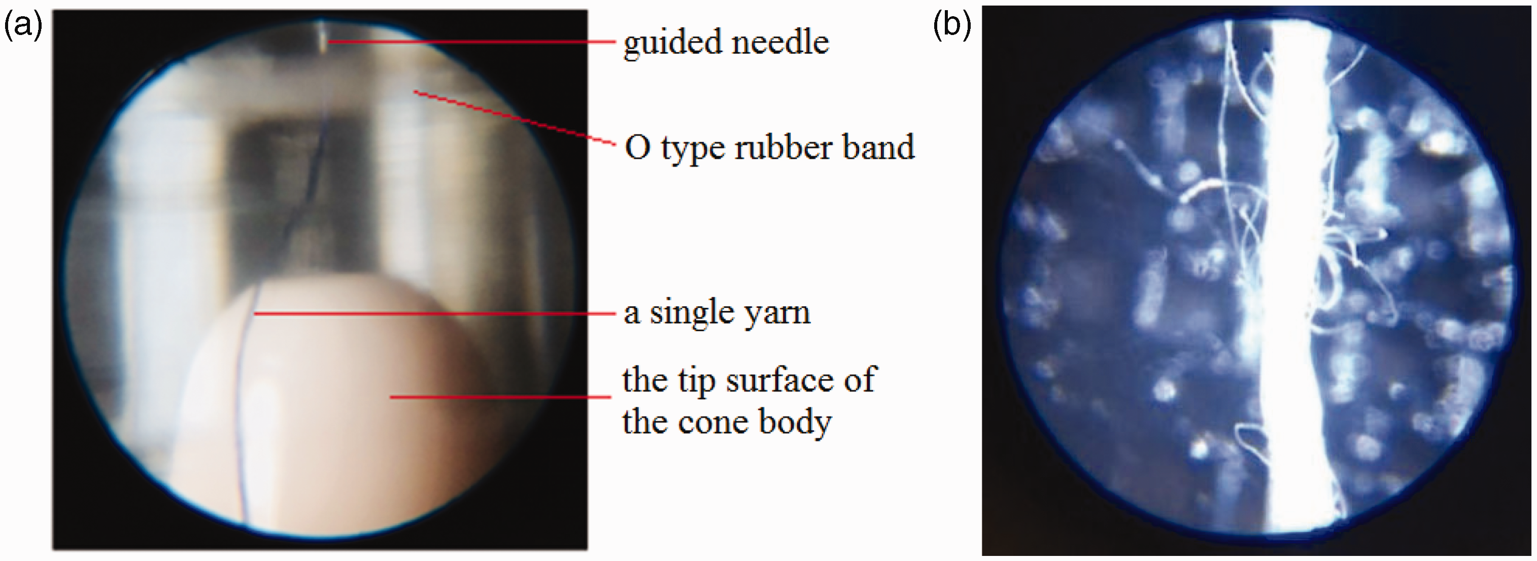
State of a single yarn under static state. (a) State of yarn photographed at 10 times magnification and (b) state of yarn photographed at 100 times magnification.

Single free-end fiber motion regularity at different times. (a) t = 0 s; (b) t = 0.5 s; (c) t = 1 s; (d) t = 1.5 s; (e) t = 2 s; (f) t = 2.5 s; (g) t = 3 s; (h) t = 3.5 s; (i) t = 4 s; (j) t = 4.5 s and (k) t = 5 s.
In this study, the research object is a single free-end fiber (not the whole fiber, it is just a free end, about 5 mm tail segment of the fiber, as described in the section on “Grid generation of free-end fiber” above), the head end of the free-end fiber is held by the fiber bundle and fixed in the yarn body, and its tail end moves along with the high speed swirling air flow. Therefore, the movement of a single free-end fiber in the high speed air flow can be regarded as fixed-axis rotation. Figure 10 shows the morphology of a free-end fiber. Since the vortex tube used in the observation experiment is made of plexiglass, the picture taken is partly reflective, but the motion trace of a single free-end fiber can still be seen. In order to facilitate the observation of the free-end fiber moving with the high speed swirling air flow, the free-end fibers are marked in red and green in Figure 10(j). At present, due to the performance limitations of the equipment, the filming interval is 0.5 s.
When the fiber moves in the nozzle, it is surrounded immediately by the high speed air flow. In general, fibers are subjected to four main types of torque as they move with the air flow: the heavy moment of the single free-end fiber, the holding moment of the head end of the single free-end fiber by the yarn body, the impact moment of the air flow, and the friction moment between the free-end fiber and the wall surface. Because the weight of a single free-end fiber is very small, its heavy moment is ignored. In addition, since the interaction between a single free-end fiber and the inner wall of the nozzle or other fibers is instantaneous, and the motion of a single free-end fiber is considered in this study, the friction torque of a single free-end fiber is ignored during calculation. Finally, only the holding moment of the head end of the single free-end fiber and the impact moment of the air flow are considered. Therefore, in the high speed swirling air flow, a single free-end fiber changes from one-dimensional stable motion to 3D unstable rotation motion, and produces nonlinear deformation such as straightening, bending, and twisting.
In order to compare with the simulation results, 11 consecutive images were selected for analysis. When t = 0 s, the fibers have not been separated from the fiber bundle, as shown in Figure 10(a); from t = 0.5∼3 s, the fibers are separated from the fiber bundle and become free-end fibers, then falling on the cone body surface, as shown in Figure 10(b)–(g); from t = 3.5∼5 s, more free-end fibers can be seen lying on the cone body surface, as shown in Figure 10(h)–(k). From Figure 10, when the free-end fiber moves in the high speed swirling air-flow field, it generates a large displacement and bending, without visible elongation. However, the resulting torsion cannot be determined because the fiber is too small and the performance of the filming equipment is limited. The above filming and observation of the motion process of a single free-end fiber during spinning shows the morphology of a single free-end fiber under the action of high speed swirling air flow. Qualitatively, the experimental observation is consistent with the results of numerical simulation.
Quantitative experimental verification of fiber motion simulation results
From the simulation results of the single free-end fiber movement in the anterior segment, it can be seen that the middle segment of the single free-end fiber has a large degree of deformation and obvious s-shaped spiral movement. Therefore, it is not difficult to infer that the displacement at the midpoint of the free-ended fiber is also large. In this section, the horizontal displacement generated by the midpoint of a free-end fiber is mainly used to quantitatively verify the rationality of the simulation results of the single free-end fiber movement. As described in the simulation results in the previous section, from t = 0.45 ms to t = 0.5 ms, the degree of bending and torsion of the fiber is greater when the fiber moves, so the single free end fiber moves at t = 0.45 ms is used as an example in this section. The horizontal displacement generated by the midpoint when a single free-end fiber moves during simulation and experiment is shown in Figure 11.

The horizontal displacement generated by the midpoint of the single free-end fiber. (a) Schematic diagram of numerical model and (b) schematic diagram of experiment.
During simulation, the user-defined function in the simulation software can be used to capture the horizontal displacement generated by the fiber motion: it is defined that the three different positions of the single free end fiber separating from the yarn body are different, then the three different simulation results of the horizontal displacement generated by the intermediate point when the single free end fiber moves at t = 0.45 ms are obtained, as shown in Table 1. For comparison, three experimental observation images were selected to calibrate the midpoint displacement of a single free-ended fiber, and the results are shown in Table 1.
Comparison between numerical simulation results and experimental results

It can be seen from Table 1 that in the simulation results, under the action of air-flow impact, the maximum horizontal displacement generated by the midpoint of the single free-end fiber is 0.31 mm. The displacement in the experimental results is smaller than that in the simulation results, and the relative error between the experimental results and the simulation results is smaller, both below 8%. In addition, the reason why the simulation value is larger than the experimental value is due to the limitations of simulation conditions, model assumptions, and experimental calculation methods and the flow loss (caused by the friction resistance caused by the blocking action of the solid inner wall of the vortex spinning nozzle circular pipe with a fixed length) along the path. Usually, the relative error between the simulation value and the experimental value is less than 15%, it can be considered that the simulation agrees better with the experimental result. The relative error in this study is within 8%, which verifies the rationality and accuracy of the numerical simulation results of the single free-end fiber movement, and indicates that the gas-solid coupling research method in this study is feasible. It is reasonable to expect that this model will be conveniently developed to simulate the movement of multi-fiber and multi-boundary in dynamic twisting and take into account yarn movement in the future.
Conclusions
The application of air flow in textiles is a major technological progression in this field in recent years, leading to the development direction of new technologies. Air flow runs through the whole process from fiber to yarn to textiles, mainly including melt-blown nonwovens in the nonwovens direction, vortex spinning in the spinning direction, air-jet weaving in the weaving direction, etc. In addition, air flow is also widely used in textile preparation processes, such as air-flow distribution, transportation and impurity removal, and textile post-treatment processes, such as air-flow post-treatment, cleaning and purification. Therefore, air flow is widely used and important in the textile field.
In general, these new textile processing technologies are realized based on the force exerted by high-speed air flow on fibers (yarns), and the core is the gas-solid (air-fiber) coupling effect. Since the coupling mechanism between air flow and fiber is extremely complicated, this greatly limits the development and application of new textile technologies. This research intends to focus on the common cutting-edge basic scientific problem of the gas-solid (air-flow-fiber) coupling mechanism, and the vortex spinning technology is taken as a breakthrough point for research. The study of the fiber dynamic twisting mechanism under the air-flow-fiber coupling effect was intended to be carried out. Based on the unsteady and compressible turbulence flow characteristics of the previous research, the 3D numerical simulation models of vortex spinning nozzle and a free-end fiber are established in this article. The hybrid grids including the structured hexahedral grids and the unstructured tetrahedral grids were adopted to divide the air-flow computational area, and the deformation and displacement of a free-end fiber under the action of the air-flow force were solved by the second-order nonlinear double asymptotic method and interpolation method. With the aid of a high magnification microscope, the free-end fiber motion during the spinning process was observed. The results of dynamic numerical simulation and experimental research show that:
The free-end fiber moves with s-shaped spiral motion under the high speed swirling air-flow action in the nozzle, the middle segment of the free-end fiber produces a large displacement and bending, which is conducive to wrapping the free-end fiber to the yarn body. The proposed model is beneficial in the understanding of the fiber motion mechanism under the action of high speed swirling air flow and predicting the yarn quality according to fiber movement in the vortex spinning process in the future. The motion characteristics and morphological changes of the free-end fiber in the dynamic numerical simulation are consistent with experimental observations. It is shown that dynamic numerical simulation can better solve the problem of dynamic separation, aggregation, and twisting of the free-end fibers in the vortex spinning nozzle, which is difficult to observe experimentally. The results deepen the understanding of the yarn formation mechanism in vortex spinning and provide information for further spinning process improvement.
At present, the existing experimental conditions are simple and the performance of photographic equipment is not high, so the images are not clear enough and not standardized. There are limitations here of the software we used, utilizing more powerful tools for image analysis might bring possible benefits like to help measure the fiber displacement, to display the fiber morphology and to test the speed of fiber motion, etc. To explain the process of the air flow acting on the fiber with temporal and spatial characteristics is difficult, and it is also the theoretical basis for studying the dynamic process of fiber twisting. But at present, we only have access to the tools that we used. We will constantly improve and perfect our research in future.
Footnotes
Declaration of conflicting interests
The author(s) declared no potential conflicts of interest with respect to the research, authorship, and/or publication of this article.
Funding
The author(s) disclosed receipt of the following financial support for the research, authorship, and/or publication of this article: This work is supported by the National Natural Science Foundation of China (No. 52106205) and the Open Project Program of Key Laboratory of Yarn Materials Forming and Composite Processing Technology of Zhejiang Province (No. MTC-2022-01).