



Abstract
The hollow fiber composite (HFC) reverse osmosis (RO) membrane with a special self-supporting structure has attracted a great deal of attention in the fields of separation and purification. However, low permeability is an urgent problem restricting its wide application. A porous polysulfone (PSF) hollow fiber support membrane was fabricated through the dry–wet spinning technique and hydrophilic α-cellulose © powder was incorporated in the PSF membrane matrix to improve the membrane’s water permeability. The HFC RO membrane was prepared via the interfacial polymerization process on the inner surface of the C/PSF support membrane. The membrane morphology and surface hydrophilicity were evaluated through scanning electron microscopy observation and dynamic water contact angle (WCA) measurement. The effects of α-cellulose incorporation on the separation performance of PSF hollow fiber membranes and HFC RO membranes were investigated. The results showed that the surface hydrophilicity and water permeability of the PSF membrane were significantly improved after the introduction of α-cellulose. The WCA of the modified PSF support membrane decreased from 84.6° for the neat PSF membrane to 70.25°, and the pure water flux can reach a maximum value of 102.1 L/(m2 · h) (0.1 Mpa), which was 1.3 times that of the pristine membrane. The HFC RO membrane using the hydrophilic modified PSF membrane as the substrate exhibited an enhanced water flux of 15.6 L/(m2 · h) and, meanwhile, the membrane salt rejection remained above 97.6% (1.0 wt% NaCl aqueous solution, 0.7 Mpa). The HFC RO membrane showed extremely high rejection rates (99%) for different dyes (congo red and methylene blue). No obvious performance deterioration was observed for the HFC RO membrane during continuous vacuum membrane distillation (VMD) experiments for 60 h.
Membrane separation technology, which combines high separation efficiency, purification, and concentration functions, has been widely applied in water treatment, special separation, and the recovery of high value-added substances. 1 As a pressure-driven membrane separation technology, reverse osmosis (RO) with extremely high salt rejection has been successfully used in various desalination fields, including seawater and brackish water desalination, 2 food processing, 3 the textile printing and dyeing industry, traditional pharmaceutical synthesis, and other desalination fields. 4 The current preparation method of the RO membrane is mainly based on the thin-film composite (TFC) technique. Compared with the homogeneous RO membrane prepared by the one-step method, such as the cellulose acetate (CA) membrane, 5 the TFC membrane can be obtained through the interfacial polymerization (IP) of diamines, such as m-phenylenediamine (MPD) or piperazine (PIP), and polyaryl chlorides, such as trimesoyl chloride (TMC), on the surface of the porous substrate membrane. Since the composite layer (i.e. the functional layer or active layer) and the support membrane can be designed and optimized separately, the RO composite membrane with excellent permselectivity can be facilely and efficiently obtained. 6
At present, most commercial RO membranes are flat sheet TFC membranes. By comparison, the hollow fiber composite (HFC) membrane with a self-supporting structure has the advantages of a large specific surface area and low operating pressure. However, its relatively low permeability has restricted its further development and application. According to the composition characteristics of TFCs, the current research on the performance improvement of the HFC RO membrane, especially the water flux, is mainly focused on the design and optimization of the polyamide (PA) functional layer and the development of the porous hollow fiber support membrane. 7 The research of new functional layers mainly involves the development of new monomers, such as polyethyleneimine (PEI), 8 the aliphatic amine bis (3-aminopropyl) amine (BAPA), 9 3,5-diamino-1,2,4-triazole (DAT), 10 and 4-(piperazin-1-yl)benzene-1,3-diamine (PMPD), 11 the surface grafting modification of the functional layer, such as polyacrylamide (PAAm) 12 and tannic acid (TA), 13 and the blending of functional substances in the active layer, such as 1-methylimidazole (1-MI), 14 the nonionic surfactant Tween 80, 15 zwitterionic functional silane monomers, (3-sulfopropylbetaine-propyl)-trimethoxysilane (SPPT), 16 and poly(amidoamine) (PAMAM)-grafted halloysite nanotubes (HNTs). 17
As the separation layer of the composite membrane, the functional layer mainly plays the key role of selective separation. In addition to the physical and mechanical support, the porous support membrane also significantly affects the rapid transfer and permeation of water molecules across the RO composite membrane. The hydrophilicity, pore structure, and porosity of the support membrane have a comprehensive effect on the mass transfer process of water molecules during the RO process. Similar to the research of the functional layer, the development of new membrane materials, membrane surface modification, and the blending modification of functional substances in the membrane matrix are the main research hotspots of the support membrane. 18 In recent years, with the emergence of high-performance materials, the substrate membrane materials for composite RO membranes have gradually expanded from polysulfone (PSF) and polyvinylidene fluoride (PVDF) to polyethersulfone (PES) polyacrylonitrile (PAN), sulfonated polyethersulfone (SPES), polypropylene (PP), polyimide (PI), and their blends. 19 Among them, PSF is widely used as the hollow fiber support membrane material due to its excellent membrane-formation property and stable chemical and mechanical properties. Lv et al. 20 employed polyvinyl pyrrolidone (PVP) and N,N-dimethylformamide (DMF) as the pore-forming agent and the solvent, respectively, to prepare a PSF hollow fiber ultrafiltration (UF) support membrane through the dry–wet spinning technique. PIP and TMC were used as the two active monomers for the IP process on the lumen side of a PSF hollow fiber substrate to obtain a HFC RO membrane. The prepared HFC membrane achieves a water flux of 20.4 L/(m2 · h · MPa) and NaCl rejection of about 98% with 2000 mg/L NaCl solution as the feed. Askari et al. 21 optimized PES hollow fiber substrates by controlling the bore and dope fluid flow rates, fiber dimension, and morphology. The TFC-PES hollow fiber membranes have a pure water permeability (PWP) of around 2.5–3 L/(m2 · h · bar) and NaCl rejection of around 97.5–98% for brackish water desalination at 20 bar. In addition, by changing the composition of the casting solution and the rate of the phase separation process to regulate the membrane microporous structure during the development of new membrane materials, a porous hollow fiber substrate membrane suitable for the preparation of HFC RO membranes can be obtained. Li et al. 22 prepared a mechanically robust tribore hollow fiber substrate containing three circular-sector channels by spinning a P84/ethylene glycol mixed dope solution with delayed demixing on the fiber lumen. The thin walls of tribore hollow fibers have a large PWP of up to 300 L/(m2 · h · bar). A defect-free PA thin film was successfully formed on the outer surface of the fabricated tribore hollow fiber membranes with the aid of vacuum sucking coating.
Compared with the development of new substrate membrane materials, the modification of hollow fiber support membranes is a simple and effective method to prepare high-performance hollow fiber support membranes for TFC RO membranes. At present, the performance improvement of hollow fiber support membranes is mostly achieved by surface modification (including surface coating and grafting) and blending modification. However, the weak binding force between the coating layer and the support membrane surface derived from the surface coating method easily causes the loss of the active groups in the long-term membrane separation and cleaning process. 23 In addition, the mechanical strength of the substrate membrane obtained by the surface modification method cannot be well enhanced at the same time. Blending is a more convenient and effective modification method than surface modification. However, due to the difference in thermodynamic properties between the modifier and the membrane matrix material during the blending process, microscopic phase separation is inevitable along with the membrane formation, which may lead to a poor membrane macroscopic properties. 24 In recent years, various novel blending substances have been used to modify hollow fiber membranes for the preparation of high-performance HFC RO membranes. PANI (polyaniline) nanofibers with an extremely high dispersion property were obtained by the IP technique and dispersed in a PSF spinning dope. The newly nanocomposite UF hollow fiber membrane prepared by the dry–wet spinning technique showed a maximum rejection of 99.25% for hazardous dye Reactive Red 120 (RR120) at a concentration of 300 ppm when subjected to a pressure of 2 kg/cm2. 25 In order to enhance the compatibility with and dispersion within the system, nanoparticles such as tungsten trioxide (WO3) nanosheets 26 and hydrophilic polymers such as hydrophilic polyamide imide (PAI) 27 were successfully introduced into the hollow fiber membrane matrix to improve the membrane hydrophilicity, water permeability, and rejection property. In addition, the compatibility of the blend with the membrane matrix and the hydrophilicity of the blend membrane can be simultaneously enhanced after the incorporation of hydrophilic modifiers with a molecular structure similar to the membrane matrix materials into the hollow fiber membrane matrix. Heidari et al. 28 incorporated carboxylic polyethersulfone (CPES) into the PES spinning dope and fabricated negatively charged CPES/PES blend hollow fiber UF membranes via the wet spinning method. The hydrophilicity of CPES/PES hollow fiber membranes showed a significant improvement with a decrease of water contact angle (WCA) from 76° (neat PES) to 42°. The permeability increased up to about three times that of the neat PES membrane, while the rejection only decreased from 94% to 86%. Some modified porous membranes not only have separation characteristics, but also have special functionalities and can be used in advanced application fields such as biosensor design, 29 high-temperature processing, 30 fuel cells, 31 boosting agricultural production, 32 bone regeneration, 33 and other high-tech fields.
As a natural hydrophilic modifier, cellulose (C) has a wide range of sources, and a large number of hydrophilic hydroxyl groups are densely bound on the molecular surface. If cellulose (without any modification and treatment) can be directly used for the hydrophilic blending modification of hollow fiber membranes, the modified membranes are expected to be applied in the preparation of high-performance HFC RO membranes. In addition, it should be pointed out that compared with other synthetic polymeric modifiers, the use of cellulose can reduce the consumption of fossil raw materials and promote carbon peaks and carbon neutralization. Due to the insoluble and refractory nature of natural cellulose, previous research has mainly focused on how to dissolve natural cellulose through chemical modification, such as the synthesis of CA and carboxymethyl cellulose (CMC), 24 or searched for good solvents, such as N-methylmorpholine-N-oxide (NMMO). With the development of cellulose processing technology, micro-nano cellulose powder or cellulose nanofiber can be directly obtained by the physical microfluidizer or ball milling methods. The physical and chemical properties of cellulose powder of smaller size will be greatly changed and, hence, micro-nano cellulose exhibits a promising application prospect.
In this study, hydrophilic α-cellulose (C) powder was directly introduced into PSF spinning solution. A C/PSF hollow fiber membrane was fabricated through the dry–wet spinning technique and employed as the substrate for the preparation of a HFC RO membrane. The HFC RO membrane was obtained through the IP process of MPD and TMC on the inner surface of a PSF hollow fiber support membrane. The membrane surface morphology and surface hydrophilicity were evaluated through scanning electron microscopy (SEM) observation and dynamic WCA measurement, respectively. The effects of α-cellulose introduction on the separation performance of the PSF hollow fiber membrane and the HFC RO membrane were well investigated.
Experimental details
Materials
PSF particles (Solvay, Udel-3500) were dried in a vacuum oven at 80°C for 12 h before use. Compound additives composed of polyethylene glycol (PEG, MW = 6000), lithium chloride (LiCl), a and surfactant were purchased from Tianjin Kemiou Reagent Co., Ltd (China). 1,3,5-TMC (≥99%), MPD (≥99%), and α-cellulose microcrystalline (i.e. α-cellulose powder (≤25 μm)) were obtained from Shanghai Jingchun Biochemical Technology Co., Ltd (China). Egg albumin (EA), congo red (CR), methylene blue (MB), N,N-dimethylacetamide (DMAc), and n-heptane were supplied by Fuchen (Tianjin) Chemical Reagent Co., Ltd (China).
Preparation of the C/PSF hollow fiber support membrane and membrane module fabrication
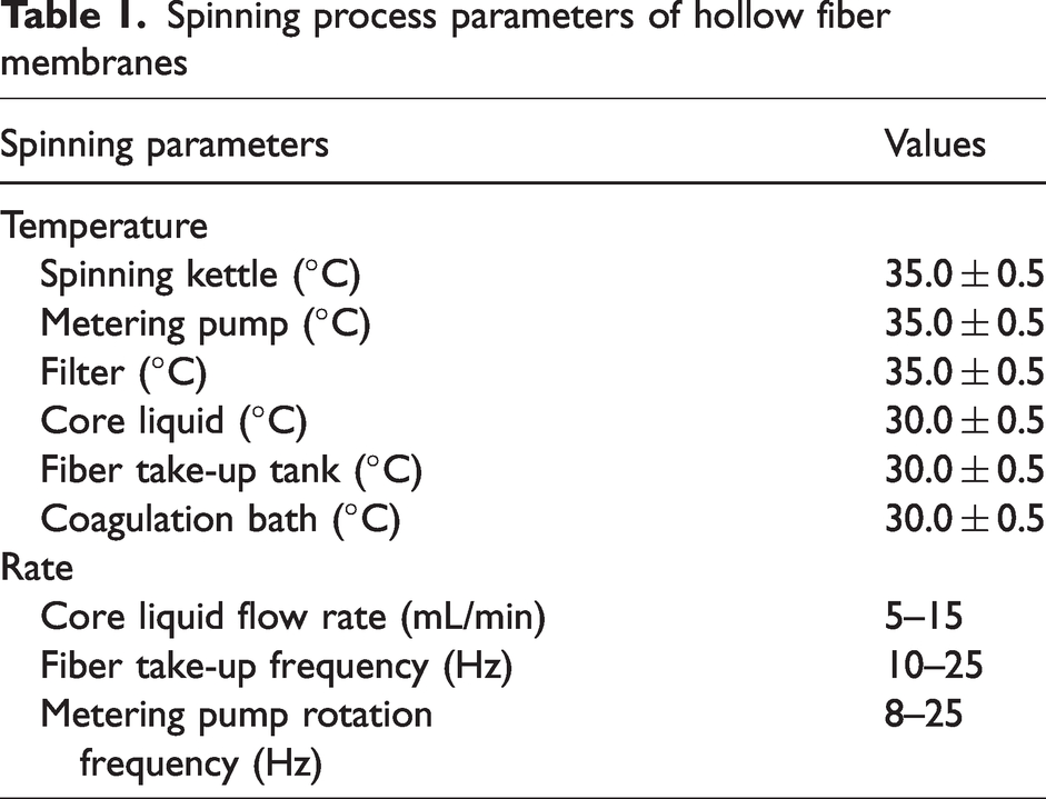
The C/PSF hollow fiber support membrane was prepared through the dry-jet wet spinning technique, as illustrated in Figure 1. The membrane-formation process was based on the non-solvent induced phase separation (NIPS) mechanism. A detailed description can be found in our previous report. 34 A certain amount of cellulose powder was added into the solvent (DMAc) under ultrasonic dispersion for 2 h and the dispersed solution was poured into a spinning kettle. A certain amount of dried PSF particles were added into the DMAc in the spinning kettle under moderate stirring for about 8 h at 60°C until a homogeneous solution was obtained. Then, the compound pore-forming agents were introduced into the PSF solution followed by continuous stirring for 3 h. After degassing overnight, the spinning solution was successively squeezed out of the spinning kettle under high-pressure nitrogen into the filter and extruded into the central annular gap of the spinneret (inner diameter/outer diameter = 0.7/1.3 mm) by the metering pump. Meanwhile, the core liquid (10 wt% DMAc aqueous solution) flew out of the central tube of the spinneret under high-pressure nitrogen. The liquid filament passed through an air distance of 5 cm and then was immersed in the coagulation bath for instant solidification. After a 4-m-long coagulation bath, the nascent hollow fibers were wound up. The hollow fibers were taken from the winding barrel and soaked in pure water. Fresh water was changed every 12 h. After immersing for 48 h, the final C/PSF hollow fiber support membranes were obtained. Table 1 lists the spinning process parameters of the hollow fiber membranes. The spinning dope was composed of PSF (17 wt%), DMAc (75 wt%), PEG-6, 000 (6 wt%), LiCl (1 wt%), and surfactant (1 wt%). The contents of cellulose powder in the spinning solution were 0%, 1%, 3%, 5%, and 7%, respectively, and the as-spun hollow fiber support membranes were designated as C/PSF-0, C/PSF-1, C/PSF-3, C/PSF-5, and C/PSF-7 in sequence. The molecular formula of α-cellulose and PSF are shown in Figure 1. A large number of hydrophilic hydroxyl groups are bound on the surface of the cellulose, which can be expected to improve the hydrophilicity of the membrane material itself. The PSF molecule with the rigid structure of the benzene ring endows the hollow fiber membrane with excellent mechanical strength.
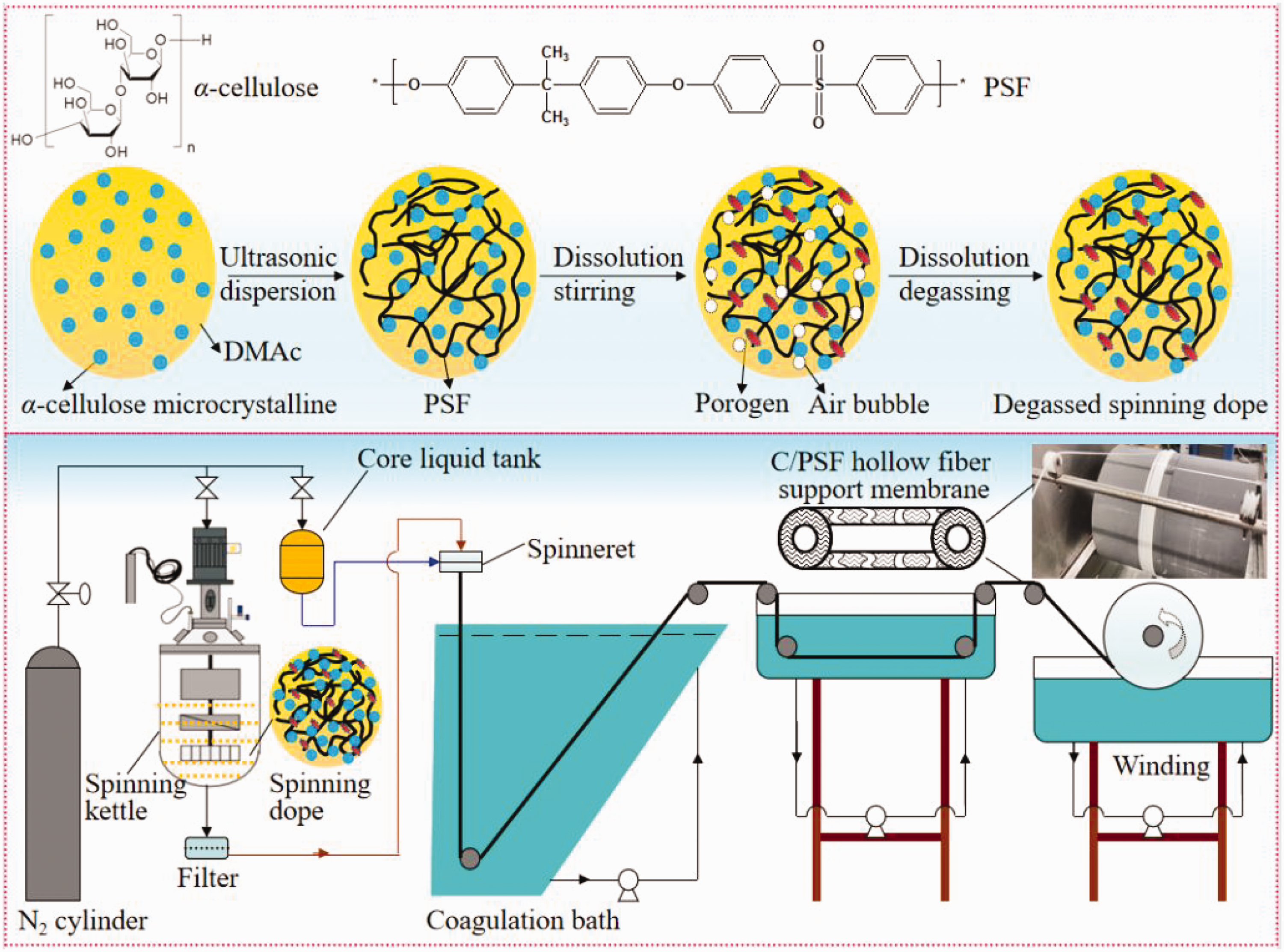
Schematic diagram of the hollow fiber support membrane spinning process. PSF: polysulfone; DMAc: N,N-dimethylacetamide; C: α-cellulose.
Spinning process parameters of hollow fiber membranes
The as-spun hollow fiber support membranes were taken out of pure water and soaked in 30 wt% glycerol aqueous solution for 24 h. Afterwards, the hollow fibers were taken out and dried at room temperature for about 72 h. The two ends of 15 fiber bundles with the effective length of 1 m (the effective membrane area is about 0.044 m2) were sealed with epoxy resin. After the epoxy resin was completely cured, the excess resin at both ends was cut off until the hollow fiber lumen was exposed. The fabricated hollow fiber membrane modules were immersed in pure water, which was replaced with fresh pure water every 12 h. After three cycles of replacement, the modules were preserved in pure water for use.
Preparation of the hollow fiber composite RO membrane
The HFC membrane was prepared by the two-way coating (TWC) technique, as presented in Figure 2. Compared with traditional single-way coating, the TWC process can well avoid the uneven distribution and adsorption of monomers on the lumen surface of hollow fiber along with the long filaments of hollow fiber. It is beneficial to obtain a defect-free functional layer on the inner surface of the hollow fiber support membrane. The whole TWC process was carried out in the following sequence: MPD aqueous solution coating (i.e. aqueous phase coating), air sweeping, TMC organic solution coating (i.e. organic phase coating), and air sweeping. The aqueous phase solution and the organic phase solution were composed of 1.0 wt% MPD aqueous solution and 0.5 wt% TMC dissolved in n-heptane solution, respectively. Before the TWC process, all valves shown in Figure 2 were closed. The following are the specific steps.
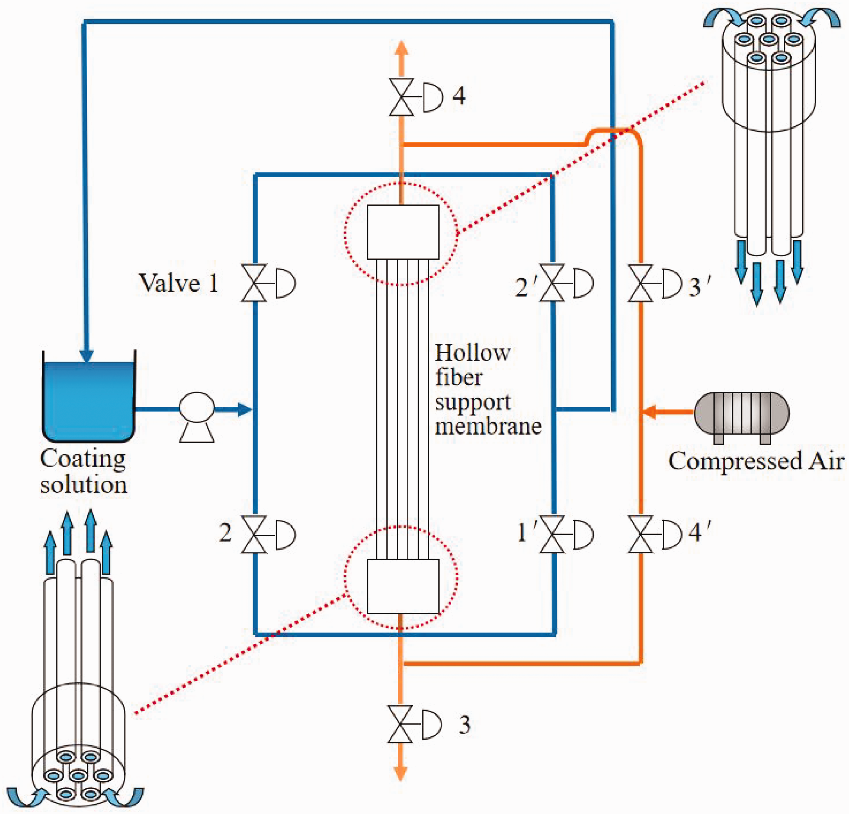
Flow diagram of the hollow fiber composite reverse osmosis membrane prepared by the two-way coating technique.
Step 1 (aqueous phase coating): after removing the residue water from the hollow fiber membrane lumen, the membrane module was installed in the TWC device, as shown in Figure 2. Valves 1/1′ were initiated and the aqueous phase solution instantly flew into the hollow fiber lumen from the top of membrane module by use of a diaphragm pump with a flow rate of 1 L/min. After continuous coating for 15 min, valves 1/1′ were closed, while valves 2/2′ were opened. After 15 min of reverse coating, the diaphragm pump was stopped and valves 2/2′ were closed at the same time, as illustrated in Figure 2.
Step 2 (air sweeping): after valves 3/3′ were opened, the sweeping air entered the hollow fiber inner cavity from the top of the membrane module through the air compressor and flew out from the bottom of the membrane module. After sweeping for 15 min, the sweeping direction of the compressed air was changed from bottom to top and the sweeping continued for another 15 min.
Step 3 (organic phase coating): the detailed coating procedure was the same as Step 1. The difference was that the coating solution was changed to TMC/n-heptane solution and the one-way coating time decreased to 1 min. When the organic phase solution contacts with the inner surface of hollow fiber support membrane, which adsorbs a great deal of MPD monomers, the IP process occurs immediately. Figure 3 presents a schematic diagram of the formation process of the thin active layer on the hollow fiber lumen and the IP reaction equation for the formation of the PA active layer. With the organic phase coating, the crosslinking degree of the PA functional layer formed on the inner surface of the support membrane gradually increased and the structure of the functional layer gradually stabilized.
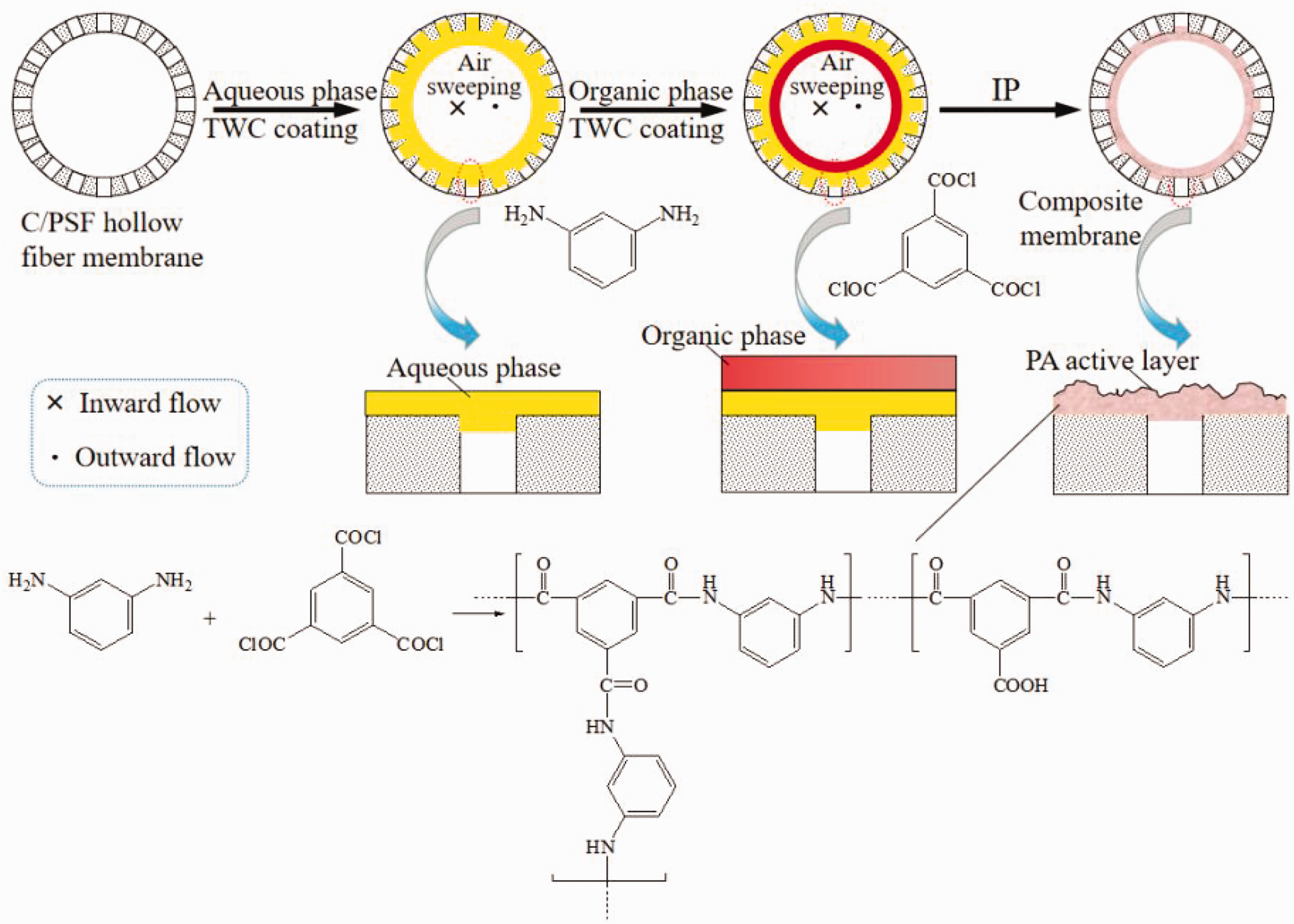
Interface polymerization reaction equation between the m-phenylenediamine and thin-film composite. C: α-cellulose; PSF: polysulfone; TWC: two-way coating; IP: interfacial polymerization; PA: polyamide.
Step 4 (air sweeping): the specific air sweeping procedure was the same as Step 2, which was also carried out in two directions. The difference was that the one-way sweeping time was shortened to 1 min. Air sweeping can remove unreacted organic monomers and residue solvent in the inner cavity of the hollow fiber membrane. After air sweeping, the hollow fiber membrane module was removed from the TWC device and immersed in pure water. The water was replaced with fresh pure water every 12 h. After the pure water was replaced three times, the obtained HFC membranes were preserved in pure water for use.
Kinetics of the demixing process
In order to further evaluate the effects of the addition of cellulose powder in the spinning solution on its immersion precipitation phase separation rate, the change of solvent (DMAc) concentration in the coagulation bath (water) with time was measured to indirectly reflect the change of the membrane demixing rate. A certain weight of spinning solution (1 g) was added into the quartz cell (1 cm × 1 cm × 5 cm) followed by the quick dropping of a certain volume of pure water (1 mL). Then, the quartz cell was put into an ultraviolet (UV) spectrophotometer and the UV transmittance was determined at 196 nm at an interval of 5 s until the transmittance was approximately stable.
Characterization of different hollow fiber membranes
Morphologies
The morphologies of different hollow fiber membranes were observed through SEM (FEI Quanta 250, USA). Membrane samples were freeze-dried for 24 h and brittle fractured in liquid nitrogen before SEM observation. The obtained samples were attached to the sample stage with double-sided tape, followed by gold sputtering. The morphology of the cellulose powder used in this study was also observed by SEM and its size distribution was determined by diameter measurements of 100 particles in the SEM images using Image J software (NIH). 35
Structural parameters
The porosity of the hollow fiber membrane was defined as the ratio of the pore volume to the membrane geometrical volume.
36
The data for the membrane porosity was determined by the weight difference method and is calculated by Equation (1):

Surface hydrophilicity
The hydrophilicity of the inner surface of different hollow fiber membranes was evaluated by dynamic WCA measurements (CM3250-DS3210, Germany). Hollow fiber membrane samples were cut open with a sharp knife and freeze-dried for 12 h. Then, the membrane samples were evenly pasted onto a glass sheet with double-sided adhesive and placed on a sample table for observation. One water droplet was dropped on the membrane surface with an automatic piston syringe at ambient temperature and real-time pictures at the interface within 60 s of contact time were continuously captured by a camera.
Separation performance of hollow fiber membranes
The separation performance of the hollow fiber membrane was tested by the device shown in Figure 4. The feed solution at a constant temperature (25 ± 0.1°C) was circulated through the diaphragm pump. The feed liquid flew through the inner cavity of the hollow fiber membrane under a certain pressure, permeated the wall of the hollow fiber membrane to the outer surface, and the concentrate flew back to the feed tank for further reuse and circulation. The feed solution in this study includes pure water, protein aqueous solution (EA), and PEG aqueous solution, which were used for support membrane characterization and inorganic salt solution (NaCl, MgSO4), and dyes (CR; MB), which were for used for RO membrane characterization. The operating pressures for the support membrane and RO membrane were 0.1 and 0.7 MPa, respectively. In addition to the dye concentration of 0.5 g/L and NaCl concentration of 1.0 g/L, the concentration of the other solutes was 1 g/L. The data were collected after the permeate outflow was stable. All data were averaged three times to reduce the experimental error.
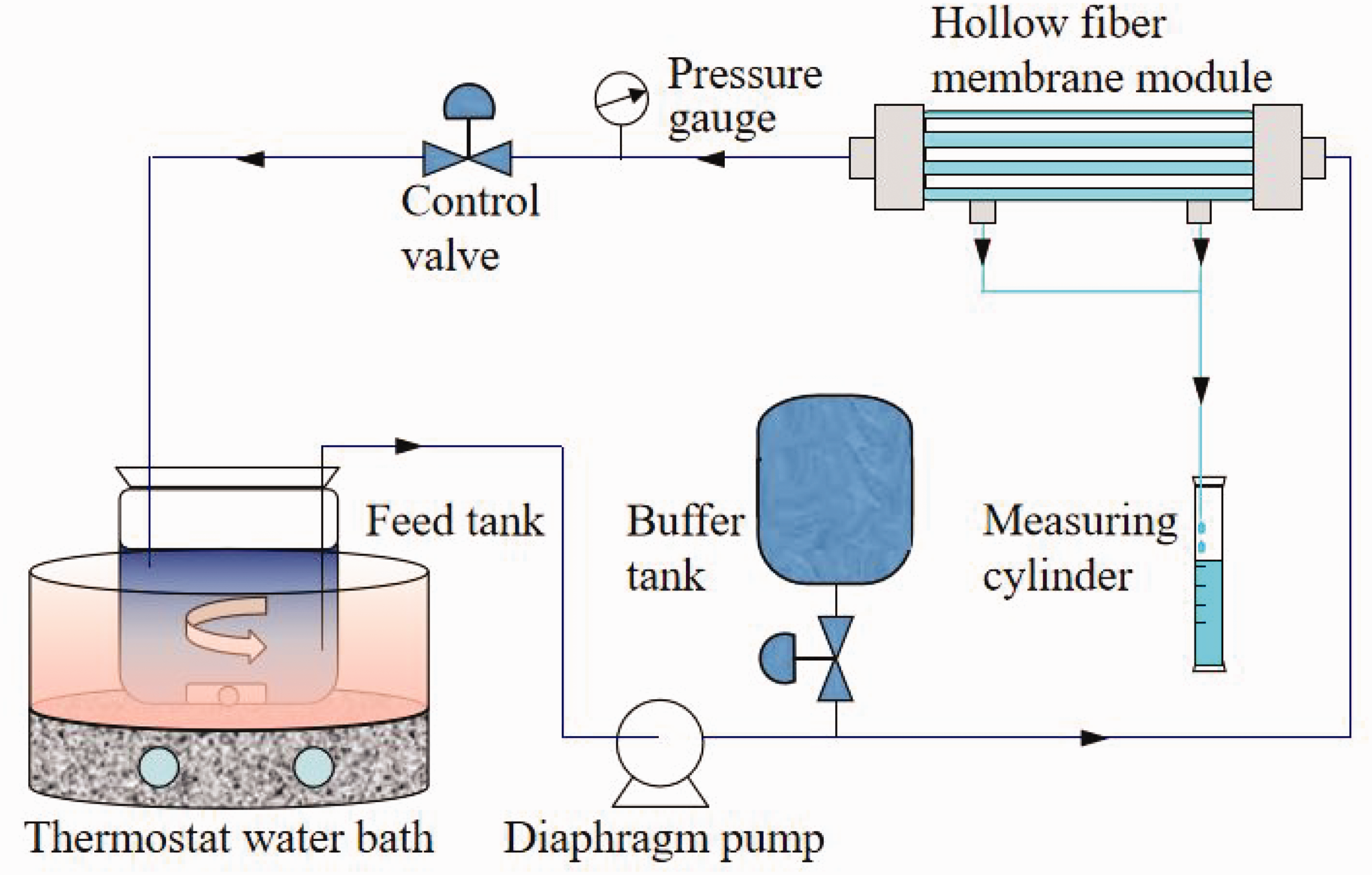
Schematic diagram of the separation performance test device of the hollow fiber membrane.
The water flux (F, L/(m2/h)) can be obtained by Equation (2):

The concentrations of PEG-20, 000, PEG-6000, and EA in the feed and the permeating solutions were measured by an ultraviolet-visible (UV-vis) spectrophotometer (TU-1901, Purkinje General Instrument Co. Ltd, China). The rejection (R) of different solutes was calculated by Equation (3):

Results and discussion
Morphology of cellulose powder
Cellulose powder can be obtained by the refining of dilute cellulose suspensions under mechanically high-pressure treatment from a wide range of natural sources, as illustrated in Figure 5(a). The surface SEM images of cellulose powder used in this study and its size distribution are measured in Figures 5(b) and (c), respectively. It can be seen that the morphologies of the cellulose powder were uneven, including round and strip-like shapes. The corresponding size was mainly distributed in the range of 10–20 μm. The small size distribution of cellulose powder would be beneficial to its uniform distribution in the spinning solution, which also should take into account the cost and technical difficulties.

Schematic diagram of the cellulose source (a), surface scanning electron microscopy (SEM) images of the cellulose powder (b), and size distribution of the cellulose powder in SEM photos measured by NIH software(c).
Morphologies of different PSF hollow fiber membranes
Figure 6 presents the local cross-sectional images of different PSF hollow fiber membranes. It can be seen that the as-spun PSF hollow fiber membrane exhibited a typical double-row finger-like pore structure obtained by the dry–wet spinning technique. This structure would be well formed through the bidirectional diffusion of water-solvent molecules in the lumen and outside of the liquid filament extruded by the spinneret. This porous structure was conducive to balancing the requirements of stable mechanical strength of the membrane itself and the high water flux of the separation membrane.37,38 It can be found through careful observation of Figure 6(a) that the lateral finger-like pores of the original PSF hollow fiber membrane were shorter and less developed than those on the side near the inner surface. With the introduction of cellulose powder, the finger-like pores in the lumen side of the hollow fiber membrane gradually grew and extended down to the outside surface; meanwhile, the membrane outer layer became more porous and looser, as shown in Figures 6(b) and (c). When the content of cellulose powder in the spinning dope continued to increase to 5 and 7 wt%, the outer finger-like pores cannot be fully developed and some voids appeared, as presented in Figures 6(d) and (e).
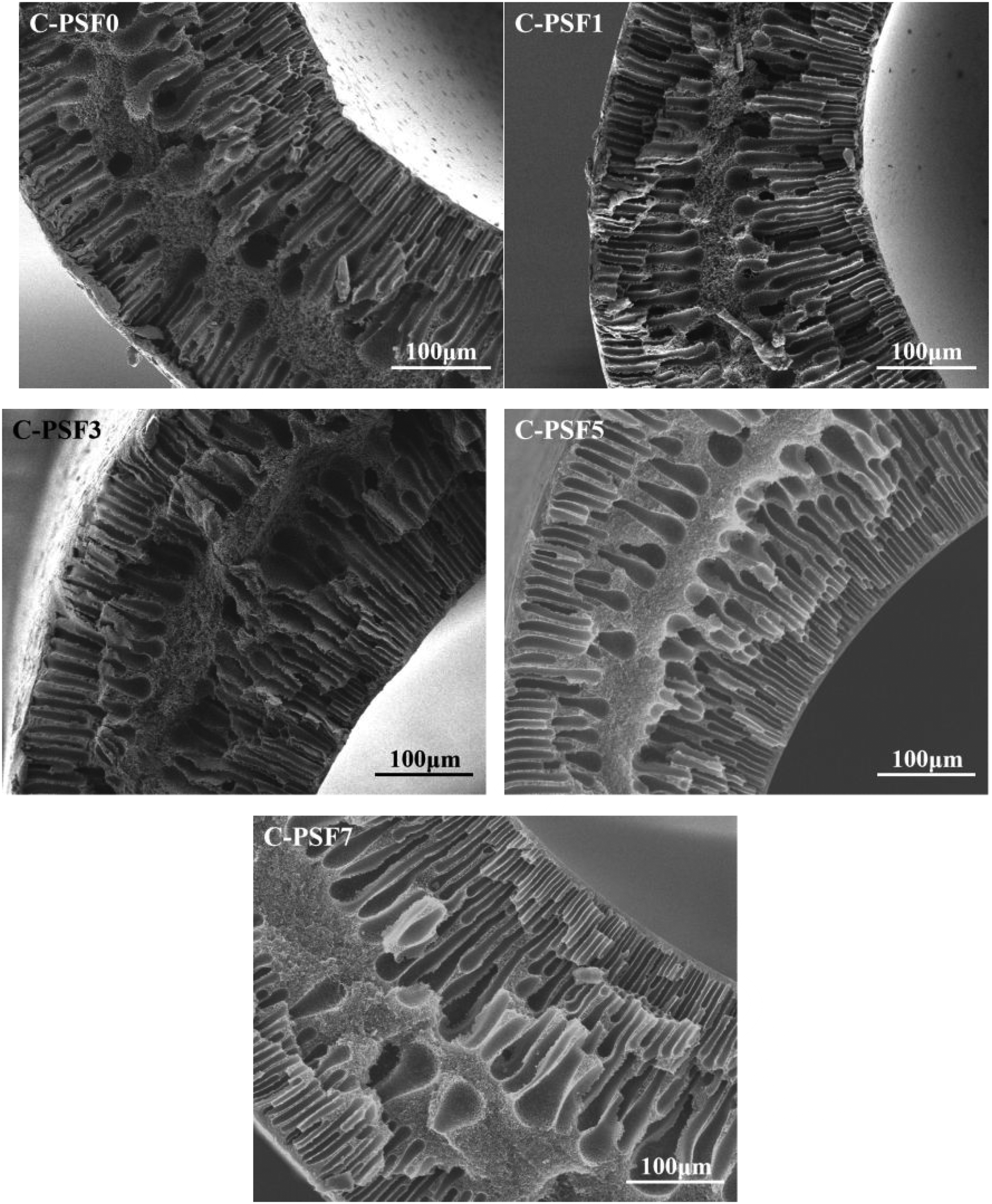
Local cross-sectional images of different polysulfone (PSF) hollow fiber membranes (×200).
The introduction of low-concentration hydrophilic cellulose powder in the spinning solution delayed and slowed the phase separation process (i.e. demixing process), so the finger-like pores can have sufficient time to slowly develop and grow. When cellulose powder with a high concentration was incorporated, the possible aggregation of cellulose powder would make the physical and chemical properties of the spinning solution deteriorate locally, thus causing accelerated demixing and hence forming a loose and porous structure with a few large voids near the outer layer. The membrane-formation rate can be reflected by the change of solvent concentration in the coagulation bath. Therefore, the variations of the contact time between different spinning solutions and the coagulation bath (pure water) with the transmittance of the coagulation bath measured by the UV spectrophotometer were obtained. The corresponding curves were drawn as shown in Figure 7. It can be seen that the transmittance decreased rapidly before 30 s. This stage was the rapid membrane-forming period, which was the key process of membrane pore formation. In order to compare the demixing rate at this stage, the curves of the first 30 s were linearly fitted, and the fitting results are shown in Figure 7(b). By comparing the slope, the demixing rate of different spinning dopes can be obtained as follows: C-PSF3 < C-PSF1 < C-PSF0 <C-PSF5 < C-PSF7. This was consistent with the above analysis of SEM observations. Previous studies have also shown that the addition of hydrophilic substances, such as polydopamine-sulfobetaine methacrylate (P(DA-SBMA)) 39 and covalent organic framework (COF) (TpPa) nanofibers, 40 can lead to thermodynamic instability of the membrane casting solution, in turn resulting in instantaneous demixing during the phase separation process. The introduction of cellulose powder in this study contributes to the formation of a more porous membrane structure, which would be bound to induce changes in the performance of hollow fiber membrane.

Demixing rate of different spinning dopes (a) and the correspond linear fitting curves (b). C: α-cellulose; PSF: polysulfone.
Surface hydrophilicity of different PSF hollow fiber membranes
The hydrophilicity of the separation membrane has a direct impact on its final water flux, which is also the main reason why scholars have been committed to improving the hydrophilicity of the membrane.41–43 In addition, for the porous hollow fiber membrane used as the substrate for the composite membrane, a hydrophilic membrane surface would be more conducive to the adsorption and distribution of aqueous monomers on it. 44 Membrane surface hydrophilicity was determined by measurements of the WCA, and variations of the WCAs of different PSF hollow fiber membranes with contact time are shown in Figure 8(a). It can be seen that the initial WCA of the pristine PSF membrane was 84.6°, followed by a decrease to 80.21° after 60 s of water contact. With the introduction of cellulose in the membrane matrix, the WCA declined to 78.62° for the C-PSF1 membrane and the WCA exhibited a gradual decrease to 70.25° for the C-PSF7 membrane with the increase of cellulose content, as illustrated in Figure 8(a). The decrease of the WCA can well reflect the spreading state of water droplets on different membrane surfaces, as shown in Figure 8(b). The larger WCA reduction rate also further indicated that the hydrophilicity of the C-PSF hollow fiber membrane was obviously improved compared with that of the neat PSF hollow fiber membrane.
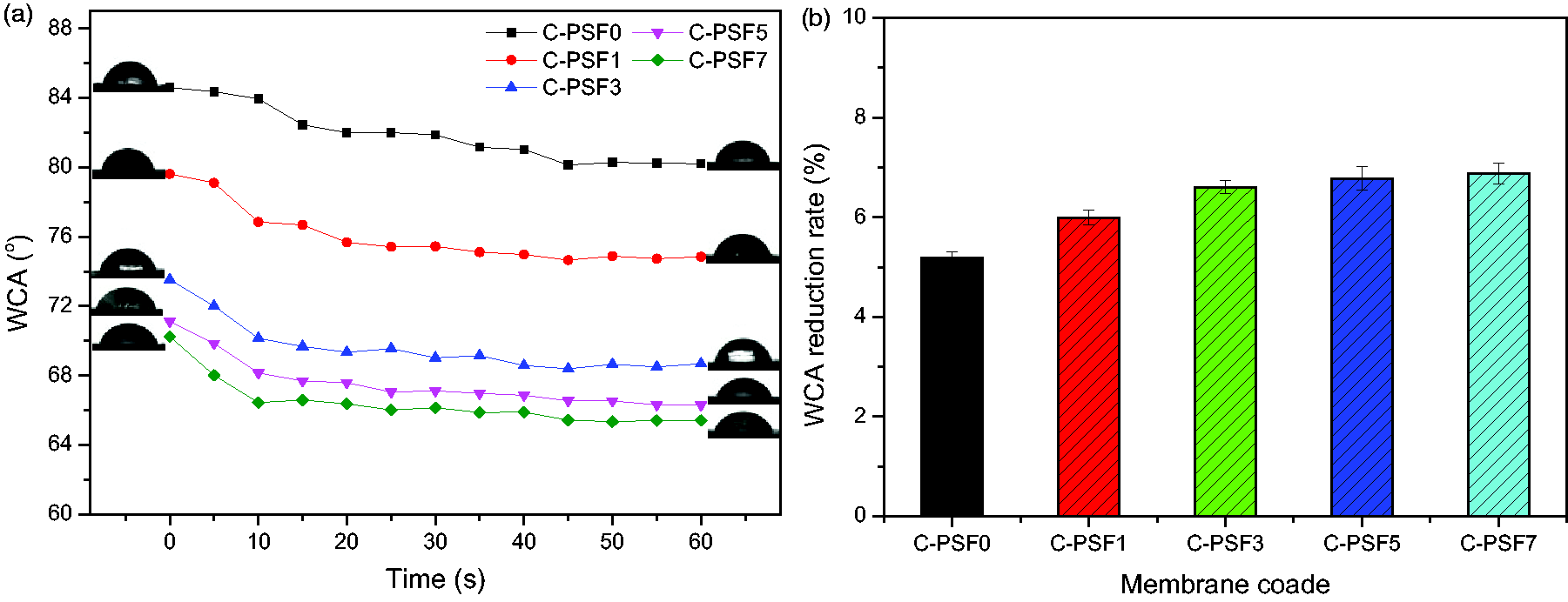
Variations of water contact angles (WCA) of different polysulfone (PSF) hollow fiber membranes with contact time (a) and the corresponding reduction rates of different membranes (b). C: α-cellulose.
For a rough separation membrane surface, the wettability of the membrane material itself and the roughness of the membrane surface are the two main factors that affect the hydrophilicity of its surface.45,46 A separation membrane with a rough surface and good wettability of the membrane material in nature would have a lower surface WCA. The emergence of a large number of hydroxyl groups derived from the hydrophilic cellulose powder in the membrane matrix facilitated the wetting of water droplets on the surface and the rapid diffusion to the membrane micropores. The formation of a loose and porous rough surface caused by the change of the phase separation process would further enhance the hydrophilic characteristics of the membrane surface. This is beneficial to the enhancement of water flux, as shown in Figure 9.

Pure water flux at 0.1 MPa and porosity of different polysulfone (PSF) hollow fiber membranes (a) and the corresponding increase rates of different membranes (b). C: α-cellulose.
Water flux of different PSF hollow fiber membranes
Figure 9 shows the pure water flux at 0.1 MPa and the porosity of different PSF hollow fiber membranes. It can be seen that the pure water flux and porosity of the neat PSF hollow fiber membrane were 78.20 ± 0.95 L/(m2 · h) and 68.12 ± 0.25%, respectively. After the introduction of cellulose powder in the PSF membrane matrix (C-PSF1), the corresponding data increased by 10% and 9%, respectively. With the increase of cellulose content, the water flux and porosity increased and gradually leveled off when the cellulose content exceeded 5 wt% (C-PSF5, C-PSF7), as presented in Figure 9(a). These trends can be clearly seen from Figure 9(b). The corresponding increase rate was defined as the percentage ratio of the increased value of water flux or porosity to their corresponding initial values. Membrane water flux is mainly caused by two factors: the hydrophilicity of the separation membrane material itself and the change of the microporous structure of the membrane.47,48 The introduction of hydrophilic cellulose endows the PSF hollow fiber membrane with a large number of hydrophilic hydroxyl groups. Water molecules can be quickly transferred from the bulk solution to the surface of the separation membrane and quickly permeate into the micropores beneath the permeation side. The increase of membrane porosity would generate more water transfer channels. The formation of a porous structure caused by the change of phase separation process contributed to the overall increase of membrane porosity, as analyzed in the Morphologies of different PSF hollow fiber membranes section. Both the enhancement of hydrophilicity and the increase of membrane porosity promoted the enhancement of membrane water flux.
Anti-compaction properties of different PSF hollow fiber membranes
Due to its high crystallinity, the strength density ratio of cellulose microcrystalline exceeds that of most engineering materials, such as ceramics, metals, and alloys. 49 Figure 10 shows the variations of the pure water flux of different PSF hollow fiber membranes with operating pressures ranging from 0.1 to 0.7 MPa. The water temperature was maintained at 25 ± 0.1°C throughout the measurement process. With the introduction of cellulose powder, the water flux of different PSF hollow fiber membranes showed an upward trend under different operating pressures, and the higher the cellulose content, the greater the water flux. In addition, it can be found from the linear fitting of the curves in Figure 10 that with the introduction of cellulose and the gradual increase of its content in the membrane matrix, the variance of the fitting line gradually increased from 0.9691 to 0.9989. The water flux of the pressure-driven separation membrane without obvious pore structure deformation should be linearly proportional to the corresponding operating pressure.50,51 The flux curve of the neat PSF hollow fiber membrane basically exhibited a linear relationship with operating pressure below 0.45 MPa. With the further increase of operating pressure, the linear trend was changed as shown in Figure 3. In contrast, the linear trend of different C/PSF hollow fiber membranes can be well maintained in the whole range of operating pressures. These results indicated that the pristine PSF hollow fiber membrane would suffer from deformation of the microporous structure under high pressure, especially when it exceeds 0.45 MPa. With the incorporation of cellulose powder in the membrane matrix, the mechanical stability of C/PSF hollow fiber membranes was improved. This contributes to a better compaction resistance and enables the PSF membrane to provide good mechanical stability and pressure resistance when used as the substrate for RO composite membranes.
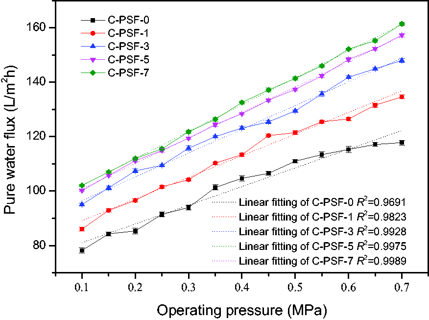
Variations of the pure water flux of different PSF hollow fiber membranes with operating pressure. C: α-cellulose; PSF: polysulfone.
Solute rejection properties of different PSF hollow fiber membranes
The rejection properties of different solutes (including EA, PEG-20,000, and PEG-6000) by PSF hollow fiber membranes were determined and the results are shown in Figure 11. It can be obtained that all PSF hollow fiber membranes presented a rejection rate of more than 90% for EA and PEG-20,000. As the molecular weight of the solute reduced to 6000 (PEG-6000), the rejection rate of all PSF hollow fiber membranes decreased to 80–85%. With the introduction and increase of cellulose powder in the membrane matrix, the rejection rate of different solutes of C/PSF hollow fiber membranes increased, followed by a slight decline. The incorporation of low-concentration cellulose delayed the demixing rate during the formation of the mixed membrane and hence resulted in a well-developed microporous structure, as observed in the SEM images in Figure 6. This induced a slight increase in the solute retention rate. The introduction of high-concentration cellulose induced an acceleration of the demixing process and thus generated a porous structure with large microvoids, as analyzed in Figure 7. This contributed to the decrease of the solute rejection rate, as shown in Figure 11. Through comprehensive consideration of various properties, C-PSF3 was selected as the substrate to prepare the HFC RO membrane and the effects of the support membrane on RO performance were investigated and compared.

Rejection properties of different solutes by polysulfone (PSF) hollow fiber membranes. C: α-cellulose; EA: egg albumin; PEG: polyethylene glycol.
Separation performance of different hollow fiber composite RO membranes
Figure 12 shows the separation performance, including water flux and solute rejection, of different HFC RO membranes. The water flux of composite RO membranes was obviously affected after the incorporation of cellulose in the PSF substrate membrane. The water flux of the four solutes basically increased by approximately 20%, while the corresponding solute rejection remained unchanged. Water molecules that penetrated through the ultra-thin functional layer can quickly pass through the micropores of the hydrophilic C/PSF hollow fiber support membrane and reach the permeation side, thus resulting in an improved water flux of the RO composite membrane, as illustrated in Figure 13. The stable solute rejections indicated that the change of the support membrane had little effect on the functional layer structure of the RO composite membrane obtained by the IP process. These results also confirmed that the water flux of the HFC RO membrane can significantly be enhanced using a cellulose-modified PSF hollow fiber membrane as the substrate, while the high solute retention performance was well maintained. Through careful comparison, it can be found that the MgSO4 rejection of the modified membrane was lower than that of the composite membrane prepared with pure PSF substrate. The incorporation of hydrophilic substance in the support membrane can accelerate the diffusion of the aqueous monomer in the IP process and hence change the microstructure of the active layer in particular, resulting in some interface defects.52,53 These variations would further contribute to a declined salt rejection. Table 2 lists the previous reports of HFC RO membranes in the past five years. By comparison, the separation performance of the HFC RO membrane developed in this study, including water flux and salt rejection, was at a medium level. Besides, the operating process was energy-saving, and was carried out under a relatively low operating pressure (0.7 MPa). It should be pointed out that the spinning process and coating parameters can be further optimized to obtain HFC RO membranes with better comprehensive performance.
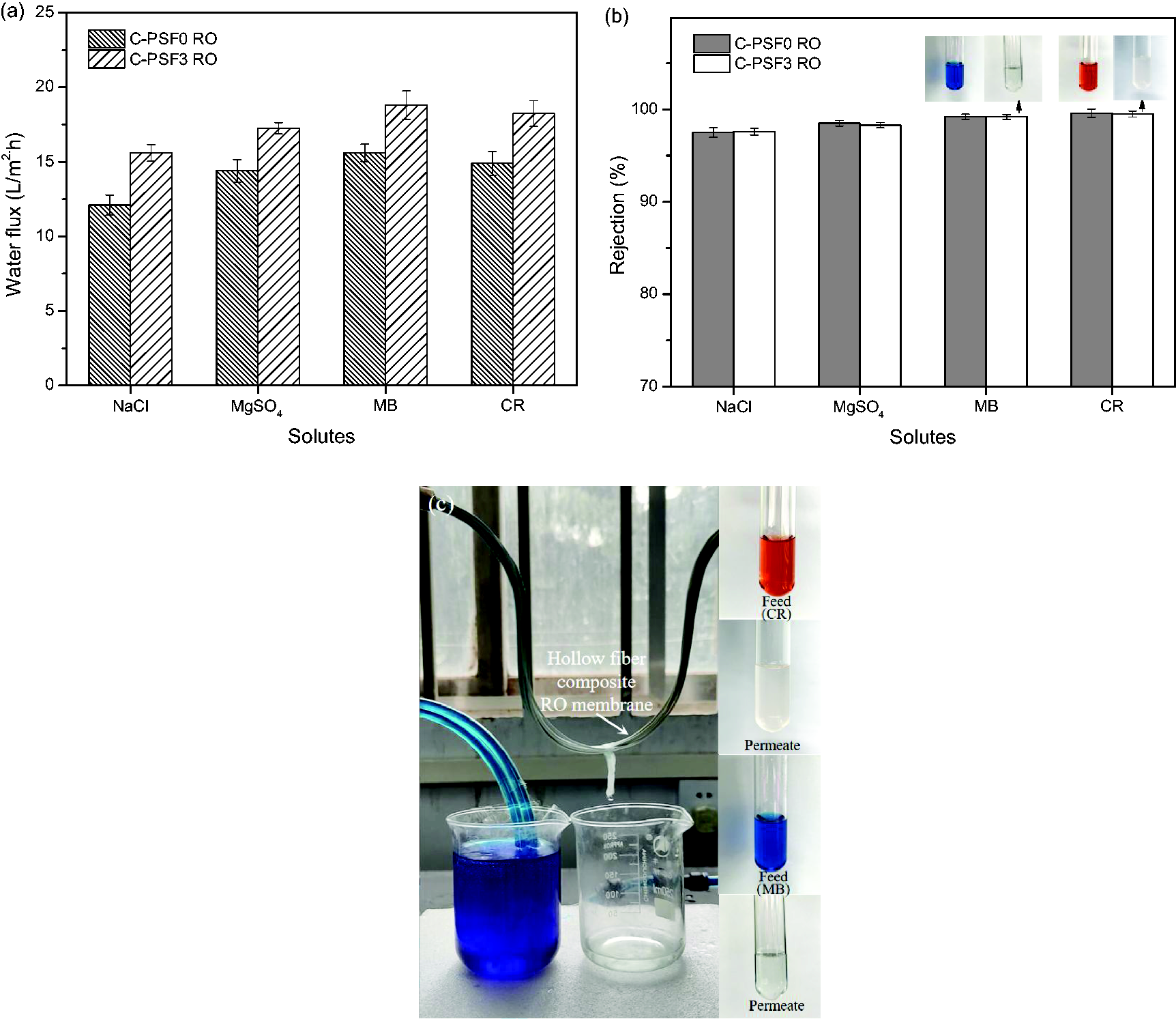
Water flux (a), solute rejection (b), and photos of the actual dye rejection test (c) of different hollow fiber composite reverse osmosis (RO) membranes. C: α-cellulose; PSF: polysulfone; MB: methylene blue; CR: congo red.
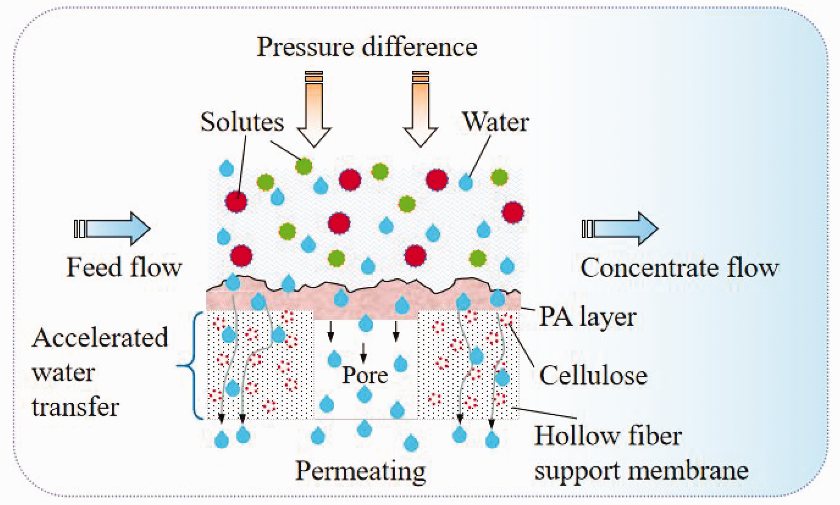
Schematic diagram of accelerated water transfer of the hollow fiber composite reverse osmosis membrane. PA: polyamide.
Comparison of the separation performance of hollow fiber composite reverse osmosis (RO) membranes reported in the previous literature in the past five years

PSF: polysulfone; PES: polyethersulfone; PSS: poly(4-styrene sulfonate); PEI: polyethyleneimine; SPES: sulfonated polyethersulfone; C: α-cellulose; TA: tannic acid; PA: polyamide; MPD: m-phenylenediamine; TMC: trimesoyl chloride; CQDs: carbon quantum dots; PDA: polydopamine; PWP: pure water permeability; TWC: two-way coating.
Long-term performance of the hollow fiber composite RO membrane
The variations of separation performance of the HFC RO membrane (C-PSF3 RO) during continuous operation for 60 h are shown in Figure 14. It can be seen that the salt retention rate of the composite RO membrane remained unchanged, basically between 97% and 98%. In contrast, the water flux was kept between 14 and 16 L/(m2 · h) and exhibited a slight decrease in the later stage of the operating process. During the whole operating period, the water flux only decreased by 5%, which could be attributed to the salt concentration polarization near the membrane surface. These results indicated that the prepared HFC RO membrane had a relatively stable separation performance.
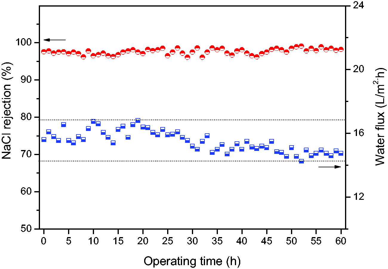
Variations of water flux and NaCl rejection of the hollow fiber composite reverse osmosis (RO) membrane (C-PSF3 RO) during continuous operation for 60 h. C: α-cellulose; PSF: polysulfone.
Conclusions
With the increasing demands in the field of RO membrane separation technology, the development of HFC membranes with higher specific surface area and the potential for high water permeability under low pressure has become one of the important breakthroughs. A novel hydrophilic C/PSF hollow fiber substrate membrane was developed and fabricated through the dry–wet spinning technique to improved its water permeability. Natural and widely sourced cellulose powder was used as a hydrophilic modifier and incorporated into the spinning dope to prepare a porous hollow fiber membrane. A HFC RO membrane was prepared via the IP process using this novel hydrophilic substrate. The changes of demixing rate facilitated the formation of a more porous and looser structure of the as-spun C/PSF hollow fiber membranes and hence contributed to an increased porosity. The membrane surface hydrophilicity was improved due to the large porosity and the enhanced wettability of the membrane material itself. The water flux of the C/PSF hollow fiber membrane was obviously increased, which was ascribed to its enhanced hydrophilicity and porous structure. The HFC RO membrane exhibited an improved separation performance, especially the permeability and long-term stable desalination properties. The cellulose/PSF hollow fiber membrane is proved to be a promising substrate for the preparation of HFC membranes with excellent permeability.
Footnotes
Declaration of conflicting interests
The author(s) declared no potential conflicts of interest with respect to the research, authorship, and/or publication of this article.
Funding
The author(s) disclosed receipt of the following financial support for the research, authorship, and/or publication of this article: This work was supported by the Program for Henan Science and Technology Development (No. 232102231065 and No. 222102240101), Scientific Research and Cultivation Fund Project of Henan University of Engineering (No. PYXM202107), Project of Youth Talent Promotion in Henan Province (No. 2021HYTP029), Science and Technology Guidance Program Project of the China Textile Industry Federation (No. 2018055) and the Key Research Project of Higher Education of Henan Province (No. 23A540009).
