
Abstract
With rapid development in the smart wearable field, new-style flexible energy storage devices are necessary to satisfy the demands of flexible smart clothing. Thereinto, fiber supercapacitors present promising application prospects. This work puts forward a facile and reliable strategy to fabricate coaxial fiber electrodes via binary wet spinning, and further assembles them into parallel or twisted nano-MnO2 fiber supercapacitors. In the obtained fiber electrode, a carboxymethylcellulose layer onto nano-MnO2 not only allows the requisite ion exchange between the electrochemical active materials and gel electrolyte, but also plays the role of separator to protect the two fiber electrodes effectively from contacting a short circuit, greatly ensuring the electrochemical stability of the nano-MnO2 fiber supercapacitors. The parallel nano-MnO2 fiber supercapacitor reaches a maximum CL of 19.7 μF/cm, EL of 0.0027 μWh/cm and PL of 1.49 μW/cm; the twisted MnO2 fiber supercapacitor achieves maximum CL, EL and PL of 49 μF/cm, 0.0053 μWh/cm and 1.0 μW/cm, respectively. Besides, the outstanding softness and tensile properties of the obtained nano-MnO2 fiber supercapacitors also guarantee stable electrochemical performance under bending, knotting or other large-distortion situations, which is beneficial to develop a new generation of metal oxide fiber supercapacitors for smart wearable clothing.
Recently, the rapid development of smart electronic products such as mobile phones and electric vehicles has put forward increasingly urgent demands for mobile control systems,1–4 which further promotes the development of lightweight and flexible energy storage systems. 5 , 6 Thereinto, fiber supercapacitors have attracted much attention due to their characteristics of small volume, light weight, high flexibility, fast charging–discharging process, high power density, long cycle life and wide range of working temperatures. 7 Compared with traditional rigid supercapacitors, flexible fiber supercapacitors can effectively avoid device failure in large-distortion situations, ensuring the safety and reliability of fiber devices in practical application. 8
As for fiber supercapacitors, the device structure is considered one of the essential factors affecting their electrochemical performance. In general, fiber supercapacitors can be assembled into three types: parallel, twisted and coaxial devices. 9 Thereinto, parallel supercapacitors consist of two fiber electrodes sealed with gel electrolyte in parallel, and they present excellent electrochemical stability due to their simple structure, which has been studied by many researchers: Liu et al. 10 designed three kinds of parallel fiber supercapacitors (straight, bent and disc) using Mn2O3 microcubic arrays loaded on the carbon fiber as active electrodes, and studied the influence of electrode arrangement on the electrochemical performance of the fiber supercapacitors; Saravanakumar et al. 11 modified three-dimensional porous Ni film@Ni fiber with NiCo2S4 nanosheets to prepare parallel fiber supercapacitors with good stability. However, the fiber devices were sealed in a plastic tube, greatly limiting their flexibility. Zhang et al. 12 prepared nitrogenous doped reduced graphene oxide (RGO)/multi-walled carbon nanotube (MWCNT)/manganese dioxide (NGC/MnO2) fiber electrodes and assembled a parallel all-solid-state fiber supercapacitor with poly(vinyl alcohol) (PVA)-LiCl gel electrolyte, which exhibits high energy density and good cycling performance. However, the parallel structure means limited ion exchange between the electrodes and electrolyte; thus, poor electrochemical storage capacity could restrict its large-scale application in practice. 13 On the other hand, twisted fiber supercapacitors are made of two fiber electrodes, twisting with each other in a gel electrolyte, which usually show better electrochemical performance than parallel devices because of the shorter ion transport path between fiber electrodes. 14 Twisted supercapacitors have attracted much attention: Ai et al. 15 reported fiber supercapacitors produced by twisting a positive electrode (CoNiO2 nanowire arrays on carbon fibers) and a negative electrode (activated carbon on carbon fibers) together around a poly(methyl methacrylate) (PMMA) backbone, which can be repeatedly subject to bending, pulling, tying and weaving. Cai et al. 16 from Fudan University reported a twisted fiber supercapacitor by coating aligned MWCNT fibers with polyaniline (PANI) and filling them with gel electrolyte. With the incorporation of PANI, the capacitance of the device can be greatly increased, and the fiber supercapacitor shows good mechanical stability without an external supporting substrate. Besides, Cheng et al. 17 also reported a high volumetric energy density twisted fiber supercapacitor with hierarchical ternary hybrids as the asymmetric electrodes, the positive electrode is a MnO2 nanosheet/poly(3,4-ethylenedioxythiophene) polystyrene sulfonate (PEDOT:PSS)/carbon nanotube (CNT) hybrid fiber and the negative electrode is an ordered mesoporous carbon (OMC)/CNT hybrid fiber, which delivered the highest specific capacitance, but the complex twisted structure could cause some difficulty in guaranteeing the consistency of fiber devices.
As mentioned above, the fabrication process of fiber supercapacitors is complicated in most of the reported literature, which may introduce several uncontrollable factors, resulting in poor electrochemical performance consistency as well as durability of fiber devices. 18 Among various fiber forming methods, wet spinning is considered a mature spinning technology to fabricate single fibers or complex fibers, 19 which can realize the continuous preparation of various fiber filaments, such as hollow fiber, 20 binary core–sheath fiber 21 and ternary coaxial fiber. 22 Therefore, through an appropriate wet spinning needle, complex fiber supercapacitors with a stable structure could be prepared in one step by multiple wet spinning technology. Recently, Liao et al. 23 from Huisheng Peng’s research group put forward a wet spinning method to produce parallel fiber batteries for 1500 km continuously, and wove them into flexible textiles, which is a practical solution for preparing wearable and lightweight fiber electronic devices. 24
This work proposes a strategy to fabricate nano-MnO2 parallel as well as twisted fiber supercapacitors based on binary coaxial wet spinning technology and the hydrothermal method. Thereinto, MnO2 nanowires were chosen as electrochemical active materials and carboxymethylcellulose (CMC) onto MnO2 nanowires was applied as a separator to avoid a contact short circuit between electrodes while allowing ions to penetrate from the electrolyte matrix to the electrochemical active materials simultaneously, so as to achieve the necessary ion transport. Then the nano-MnO2/CMC fiber electrodes were assembled into parallel or twisted fiber supercapacitors, and systemic electrochemical tests were carried out so as to estimate the electrochemical storage characteristic of nano-MnO2 fiber supercapacitors. In addition, the mechanical and softness properties of nano-MnO2 fiber supercapacitors were also analyzed for smart wearable clothing application.
Experimental details
Chemicals and materials
The applied potassium permanganate (KMnO4, 99.5%) was bought from Luoyang Haohua Chemical Reagent Co., Ltd, the manganese sulfate (MnSO4, 99%) was commercially available from Fuchen Chemical Reagent Co., Ltd, the PVA (alcoholysis degree 87–89%) and lithium chloride (LiCl, 99.9%) were bought from Aladdin reagent Co., Ltd, the carboxymethylcellulose sodium (CMC-Na, 800–1200 mPa/s) was bought from Sinopharm Chemical Reagent Co., Ltd, the acetylene black (ACET) was bought from Tianjin Jinglin New Material Technology Co., Ltd, the ethyl alcohol (C2H5OH, 99.7%) was bought from Tianjin Fuyu Fine Chemical Co., Ltd, and the calcium chloride anhydrous (CaCl2, 96%) was bought from Tianjin Damao Chemical Reagent Co., Ltd. Unless stated otherwise, all materials and reagents were used as received without further purification.
Wet spinning of nano-MnO2/CMC electrodes
Firstly, 5 mmol KMnO4 and 2 mmol MnSO4/H2O were dissolved respectively in 30 mL deionized (DI) water in a breaker, subjected to magnetic stirring for 15 min, then they were mixed together and magnetically stirred to obtain a uniform dispersion liquid. After that, the dispersion liquid was transferred into a Teflon-lined steel autoclave, heating at 140°C for 12 h in a drying oven. After the end of the procedure and after the sample had cooled down naturally, the turbid liquid was taken out and centrifugally cleaned several times, then finally dried at 60°C to obtain pure MnO2 nanowires. The process optimization, including scanning electron microscopy (SEM) and X-ray diffraction (XRD), results can be seen in Figures S1 and S2 in the Supplementary Information.
To prepare nano-MnO2 spinning solution, 0.2 g MnO2 nanowires and 0.1 g ACET were dissolved in 10 mL DI water and magnetically stirred for 30 min, then 2 g PVA was added and stirred at 90°C for 60 min, then the solution was transferred into an undefiled syringe. To prepare CMC spinning solution, 0.6 g CMC-Na powder was dissolved in 10 mL DI water, then underwent magnetic stirring at 40°C to acquire the transparent solution. Then the solution was transferred into another syringe. The optimal contents of ACET, MnO2 and CMC-Na can be seen in Figures S3–S5 in the Supplementary Information.
The binary coaxial wet spinning system used to fabricate nano-MnO2/CMC fiber electrodes is displayed in Figure 1. Thereinto, the inner channel was connected to the nano-MnO2 spinning solution, and the outer channel was connected to the CMC spinning solution. The injection rates of the two channels were set between 10 and 20 mL/h. The coagulation bath was chosen to be a mixture of water, ethyl alcohol (volume ratio of 1:5) and CaCl2 (5 wt.%).
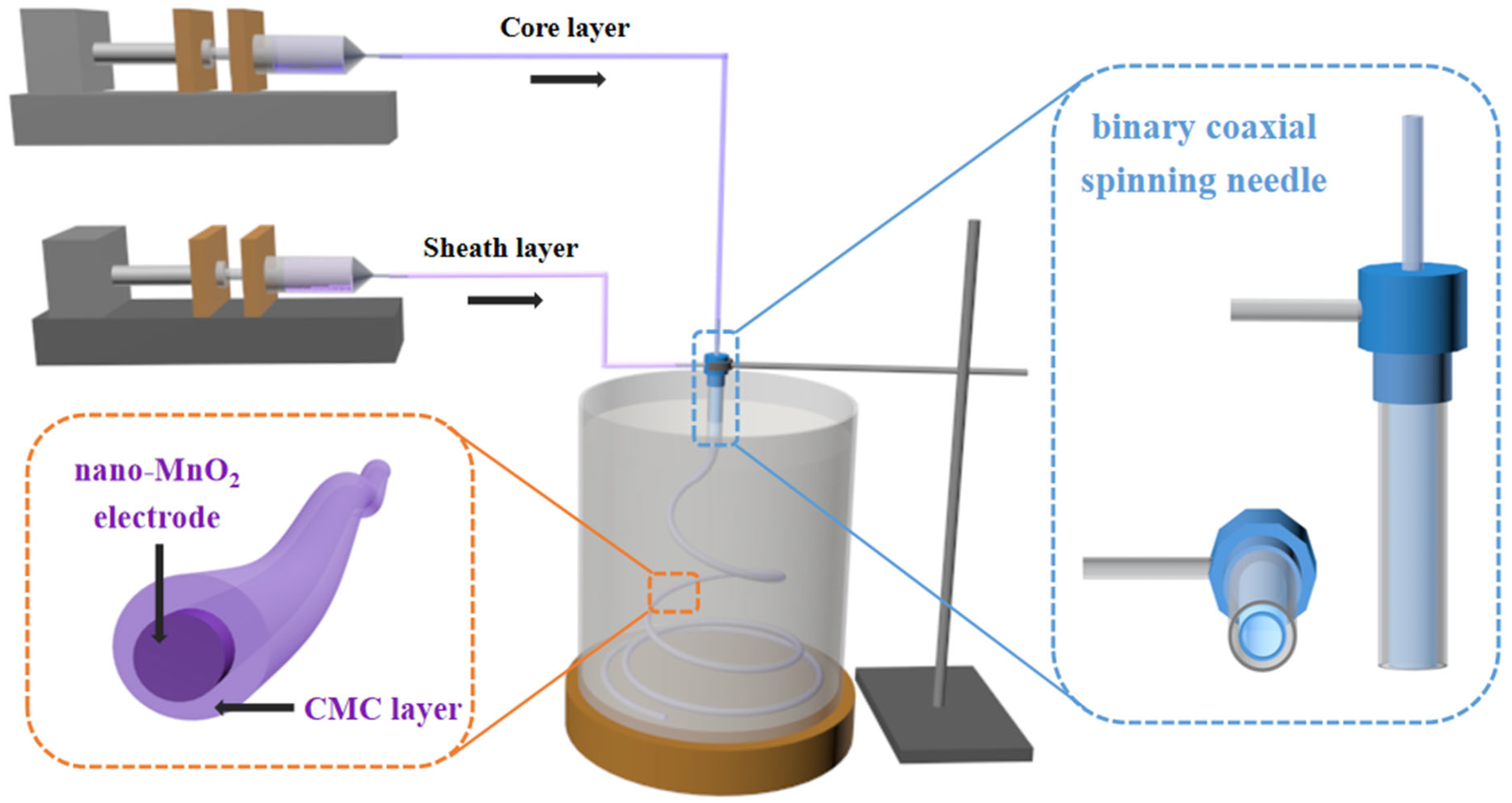
Schematic diagram of the wet spinning process. (CMC: carboxymethylcellulose).
Fabrication strategy of nano-MnO2 fiber supercapacitors: (a) parallel fiber devices. Two fiber electrodes were cut to the same length (around 4 cm), which were immersed fully in LiCl-PVA gel electrolyte for 30 s, then the two fiber electrodes were finished and dried at 60°C for 15 min. Whereafter, the immersion process were repeated three times. Then, the two fibers were put parallel to each other on a piece of release paper and surrounded in LiCl-PVA gel electrolyte, heating at 60°C for 30 min. Finally, the connected two fibers were immersed in polydimethylsiloxane (PDMS) gel for 30 s and dried at 50°C for 10 h. Eventually, metal wires were inserted at each end of the two fiber electrodes to obtain parallel fiber supercapacitors. (b) Twisted fiber devices: the immersion process of the two fiber electrodes is similar to that of the above parallel devices, but the two fiber electrodes on the release paper were twisted with each other, and except for the assembly structure, the fabrication strategy of the twisted fiber devices is the same as that of the parallel devices.
Characterization and measurements
The microstructure of MnO2 nanowires and fibers were observed by SEM (TESCAN MIRA4, Czechia), and the elemental distribution in the fibers was examined by an energy dispersive X-ray (EDX) spectroscope attached to the scanning electron microscopy. 25 The phase compositions of MnO2 nanowires were investigated by XRD (DMAX-RAPID II, Japan) in continuous scanning mode at a speed of 4°/min. The tensile test was completed on an electronic universal testing machine controlled by a microcomputer (UTM5205X, China). Moreover, the cyclic voltammetric (CV) curves, electrochemical impedance spectra (EIS) and galvanostatic charge–discharge (GCD) were recorded by an electrochemical workstation (CHI660E, China).
Electrochemical measurements
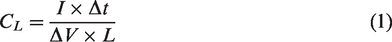
All of the electrochemical measurements of the fiber supercapacitors were carried out at room temperature using a two-electrode system. In addition, the EIS experiments were performed under a frequency from 0.1 Hz to 100 kHz with an alternating current (AC) amplitude of 5 mV. According to the GCD curves, the specific capacitances (CL, F/cm) of the fiber device could be calculated as follows:
26
Results and discussion
A cross section optical photograph of the adopted binary spinning needle is displayed in Figure 2(a), and the two independent channels ensure the coaxial structure of the nano-MnO2 fiber electrode effectively. When spinning solutions are squeezed into the coagulation bath, the coaxial fiber filament falls down vertically (seen in Figure 2(b)) and spirals into concentric circles slowly (seen in Figure 2(c)). After drying, the fiber electrode filament could be wound on a cylinder (seen in Figure 2(d)), indicating its excellent flexibility and consistency.
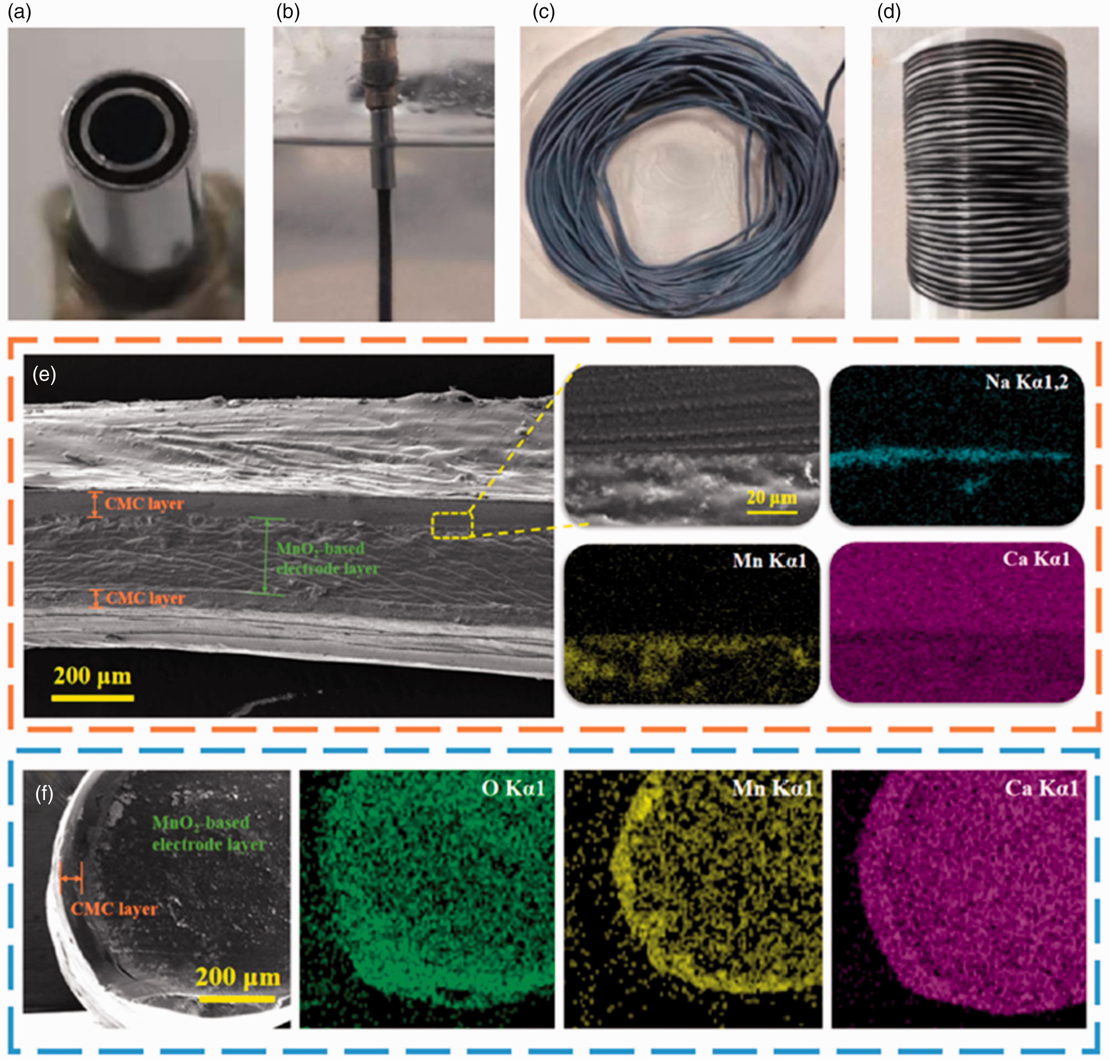
Optical photograph of (a) the cross-section of the coaxial spinning needle; (b) the spinning needle across the interface between air and the coagulation bath; (c) the electrode filament dried in air; and (d) the electrode filament tolled on a cylinder, respectively. Scanning electron microscopy images and energy dispersive X-ray elements mapping results of (e) the fiber longitudinal section as well as (f) the fiber cross section, respectively.
In order to determine the coaxial structure of the nano-MnO2 fiber electrode, Figure 2(e) exhibits a SEM image of the fiber longitudinal section. From the image, an obvious interface could be observed between the core and sheath layers, corresponding to the nano-MnO2 layer (electrochemical active materials) and the CMC covering layer (separator) of uniform thickness. On the one hand, the CMC sheath layer could protect positive and negative electrodes from a contact short circuit effectively, which is crucial during the working process of fiber supercapacitors, whether they are parallel or twisted devices; on the other hand, although CMC is a nonconductor, the special characteristic of providing efficient paths to ions between the electrode and electrolyte during the redox reactions makes it suitable for separator materials. In addition, EDX mapping results of the interface between CMC and nano-MnO2 layer can be seen in Figure 2(f). From the high-resolution SEM image, different morphologies of the core layer and sheath layer indicate an obvious interface, and the element mapping results would further illustrate it again. Thereinto, the Na element shows noteworthy aggregation near the interface, which could be ascribed to the unexchanged CMC-Na in the coagulation bath during the wet spinning process; the Mn element distributes evenly in the core layer, implying excellent stability of the nano-MnO2 in the fiber electrode; the Ca element distributed in the whole fiber proves sufficient ion exchange in the coagulation bath.
Furthermore, Figure 2(f) exhibits a cross section SEM image and element mapping results. According to the SEM image, an obvious core–sheath structure can be seen, and the complete CMC sheath layer with uniform thickness would protect the nano-MnO2 electrode layer effectively. Over the entire cross-section, the O element distributes homogeneously because of the oxygen-containing groups in both the core and sheath layers, such as MnO2, H2O and PVA; the Mn element can be seen primarily in the core layer, indicating the stability of nano-MnO2 in the fiber; more of the Ca element in the sheath layer and less of the Ca element in the core layer could be ascribed to the ion exchange process, which is consistent with the results in Figure 2(e).
The obtained nano-MnO2 electrodes could be assembled as parallel or twisted fiber supercapacitors, respectively. Figure 3 shows the electrochemical performance of the parallel fiber supercapacitor with the length of 4 cm. As is seen from Figure 3(a), two fiber electrodes (in black) are placed in parallel and isolated by gel electrolyte (in transparent) without any contact with each other, which would ensure the structural stability of the fiber device during working processes. In addition, the PDMS sealing layer on the fiber device would further ensure the isolation of the fiber device and the ambient environment, thus avoiding device failure.
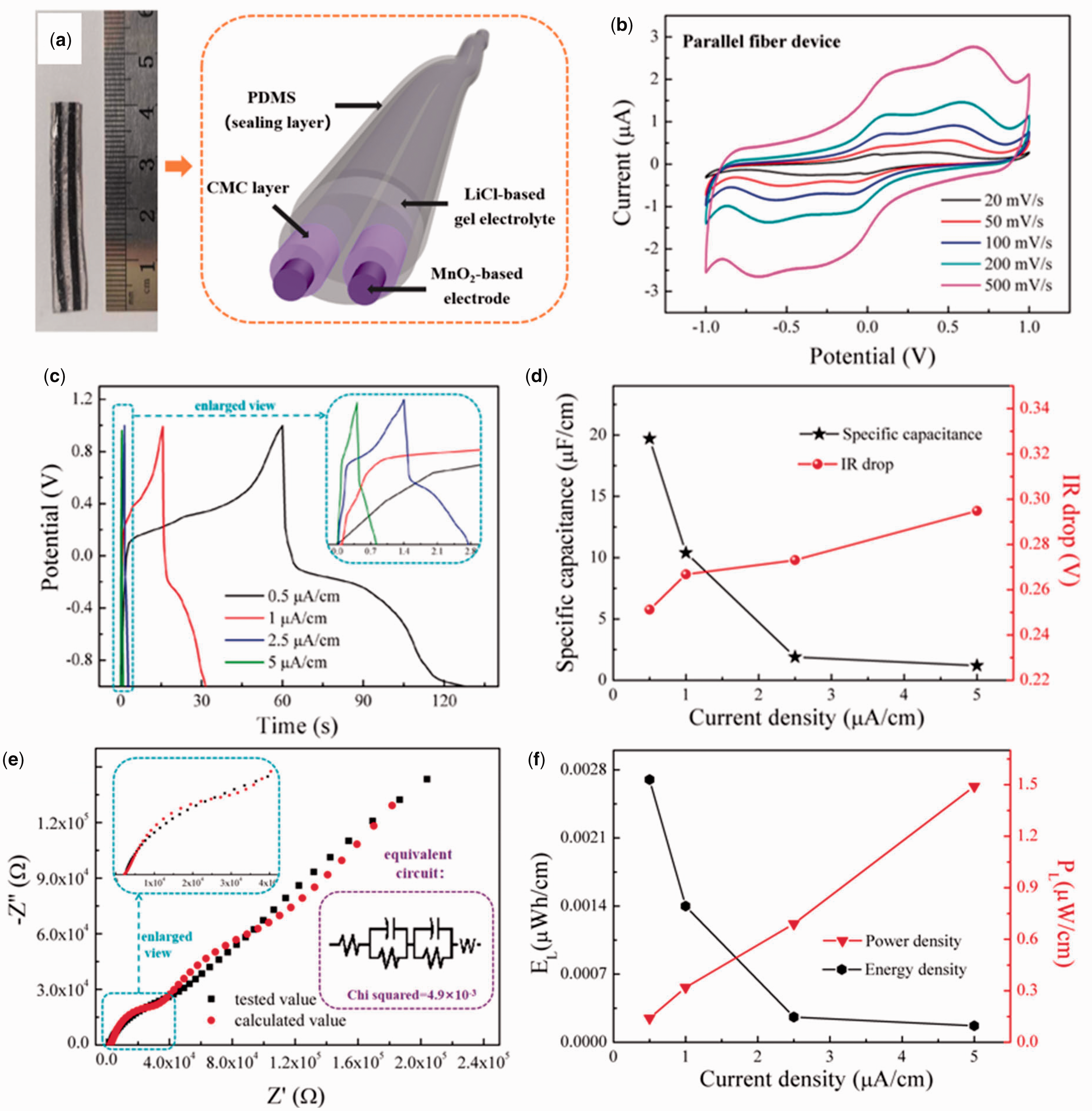
(a) Optical photograph and structural schematic diagram, (b) cyclic voltammetric curves at different scanning rates, (c) galvanostatic charge–discharge curves at different current densities and (e) electrochemical impedance spectra of the nano-MnO2 parallel fiber supercapacitor; (d) the relationship of specific capacitance as well as IR drop and (f) the relationship of energy density as well as power density versus current density of the nano-MnO2 parallel fiber supercapacitor.
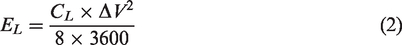
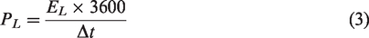
The CV curves of the nano-MnO2 parallel fiber supercapacitor at various scanning rates are displayed in Figure 3(b). From the curves, two pairs of redox peaks could be detected obviously, indicating a significant pseudocapacitance energy storage characteristic of the fiber supercapacitor, 28 and the anodic and cathodic peaks shift towards positive and negative directions with the increasing scanning rate due to larger internal resistance generated by the higher scanning rate. 29 What is more, the almost unchanged shape of the CV curves further implies superior dynamic reversibility and electrochemical stability of the nano-MnO2 parallel fiber supercapacitor. Figure 3(c) shows the GCD curves of the parallel fiber supercapacitor at current densities of 0.5, 1, 2.5 and 5 μA/cm. It can be seen that all of the GCD curves exhibit significant charging–discharging platforms, especially at low current density, which suggests typical Faraday behaviors during the testing process, inconsistent with the CV results. According to the GCD curves, specific capacitance can be calculated by Equation (1) and is displayed in Figure 3(d). When the current density increases from 0.5 to 5 μA/cm, CL decreases gradually from 19.7 to 1.2 μF/cm because of the insufficient redox reactions and limited time for ions and electrons to diffuse into the inner active materials at larger current density, 30 accompanied with the decrease of charging–discharging time. On the other hand, the IR drop can also be seen in Figure 3(d), which presents a slightly increasing trend with rising current density. On the basis of the GCD curves, the energy density and power density of the parallel device could be calculated by Equations (2) and (3), and the corresponding results are displayed in Figure 3(f). Thereinto, EL decreases constantly with current density increasing from 0.5 to 5 μA/cm, obtaining the maximum of 0.0027 μWh/cm; however, the PL value shows the opposite increasing trend at the same time, achieving the highest value of 1.49 μWh/cm at 5 μA/cm, indicating excellent electrochemical storage characteristics of the nano-MnO2 parallel fiber supercapacitor in this work. Moreover, the EIS of the nano-MnO2 parallel fiber supercapacitor is shown in Figure 3(e), which could be fitted as a calculated curve based on the specific equivalent circuit (seen in the inset). The equivalent circuit includes basic units of resistance (R), capacitor (C) and Warburg resistance (W) and the chi squared value of 4.9 × 10⁻³ prove that the fitting results are reliable. As seen from the two spectra, half circular curves at high frequency reflect the intrinsic resistance (Rs), including circuit resistance and electrolyte resistance, and the slopes of the low-frequency curves illustrate the value of charge transfer resistance (Rct), which is related to the electrochemical activity of nano-MnO2 electrodes.
Figure 4 exhibits a series of electrochemical performances of the nano-MnO2 twisted fiber supercapacitor. Thereinto, Figure 4(a) shows an optical photograph as well as structural schematic diagram of the nano-MnO2 twisted fiber supercapacitor, from which the two twisted fiber electrodes surrounded by LiCl gel electrolyte can be seen clearly, implying the effective isolation between the electrodes, further ensuring sufficient performance stability of the twisted fiber device in application.
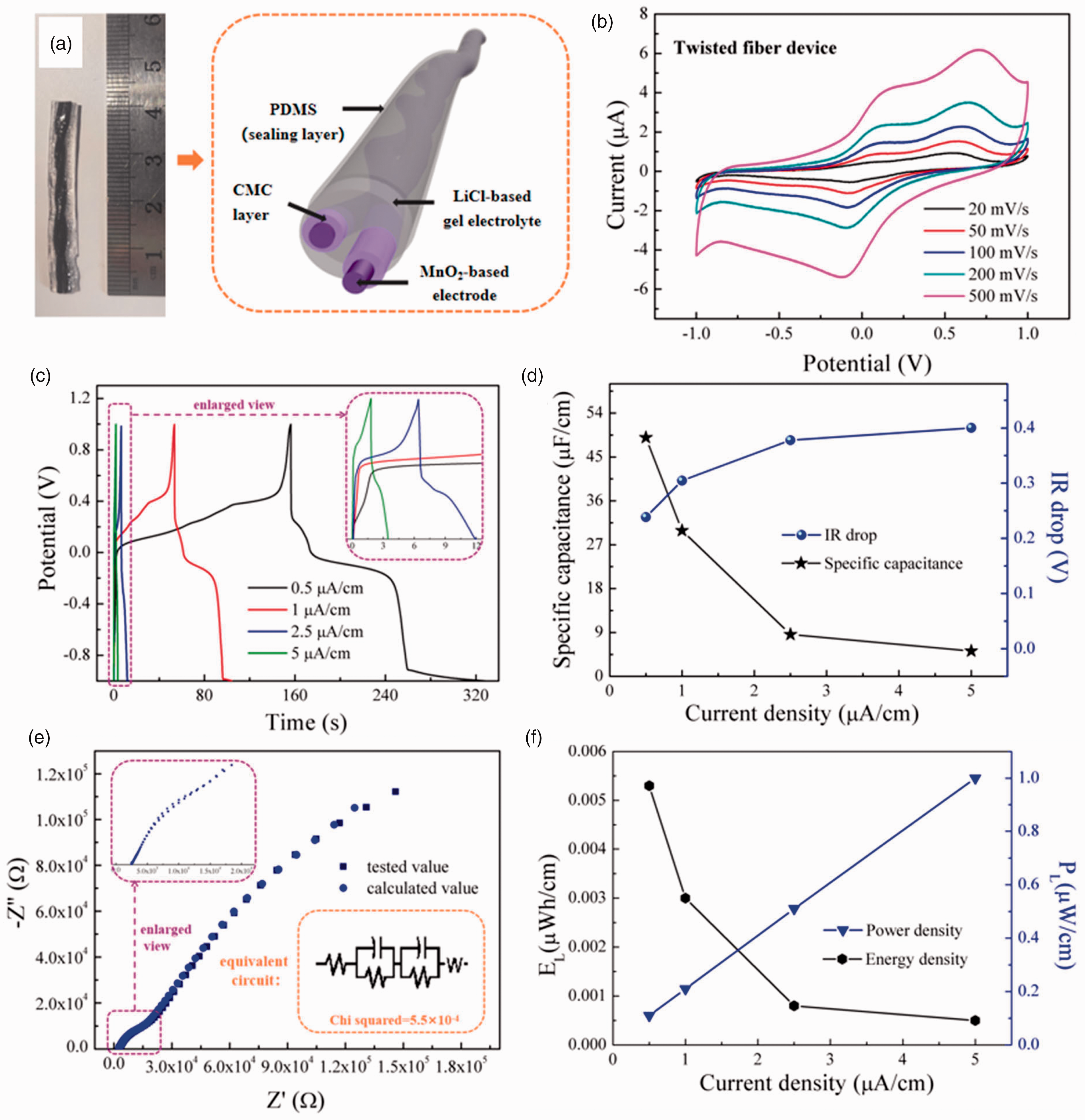
(a) Optical photograph and structural schematic diagram, (b) cyclic voltammetric curves at different scanning rates, (c) galvanostatic charge–discharge curves at different current densities and (e) electrochemical impedance spectra of the nano-MnO2 twisted fiber supercapacitor; (d) the relationship of specific capacitance as well as IR drop and (f) the relationship of energy density as well as power density versus current density of the nano-MnO2 twisted fiber supercapacitor.
Figure 4(b) displays the CV curves of the nano-MnO2 twisted fiber supercapacitor at different scanning rates. With an increasing scanning rate, the closed area of the curves rises constantly and maintains a similar shape, and the position of oxidation as well as the reduction peaks are similar to the parallel fiber supercapacitor shown in Figure 3(b), accompanied with a slight shift to higher potential, suggesting excellent dynamic reversibility and electrochemical stability of the obtained twisted MnO2 fiber device. However, the closed area as well as the maximum current value of the twisted fiber device are both larger than those of the parallel fiber device (at the same scanning rates), which indicates better electrochemical energy storage capacity. The GCD curves of the nano-MnO2 twisted fiber supercapacitor at various current densities are shown in Figure 4(c), and the inset displays enlarged GCD curves at 2.5 μA/cm as well as at 5 μA/cm. From the curves, an obvious charging–discharging platform implies violent Faraday reactions in the fiber supercapacitor, the similar shape of the GCD curves at different current densities indicates good rate ability and the decreased charging–discharging time with increasing current density is due to the incomplete Faraday reactions between the fiber electrode and electrolyte at high current density, in agreement with the corresponding results of the parallel fiber supercapacitor (seen in Figure 3(c)). In addition, the specific capacitance value as well as the IR drop of the twisted fiber supercapacitor can be calculated and is displayed in Figure 4(d). As the current density increases from 0.5 to 5 μA/cm, CL decreases from 49 to 5.2 μF/cm, obtaining the maximum of 49 μF/cm at 0.5 μA/cm, which is higher than that of the parallel fiber device, implying better electrochemical storage performance. On the other hand, the IR drop of the twisted fiber device also rises slightly with increasing current density. Furthermore, the corresponding energy density and power density can also be calculated and are shown in Figure 4(f). As seen from the results, when the current density increases, PL rises from 0.11 to 1 μW/cm, reaching the maximum at 5 μA/cm, which is lower than that of the parallel MnO2 fiber supercapacitor (seen in Figure 3(f)). At the same time, EL decreases constantly with increasing current density, obtaining the maximum value of 0.0053 μWh/cm at 0.5 μA/cm. Figure 4(e) exhibits the tested EIS (in black) as well as the fitted spectrum (in blue) of the nano-MnO2 twisted fiber supercapacitor, and the corresponding equivalent circuit can be seen from the inset. Similar to the EIS results of the parallel fiber device in Figure 3(e), the same equivalent circuit including basic units of R, C and W are applied with the reliable chi squared of 5.5 × 10⁻⁴. According to the results, the curve slope at low frequency shows a fast charge transfer rate between the electrode and electrolyte, indicating the small Rct in the twisted nano-MnO2 fiber supercapacitor.
In the actual application, electrochemical stability under distorted situations is essential for wearable fiber devices; thus, a series of measurements is carried out so as to estimate the mechanical performance of the obtained nano-MnO2 fiber supercapacitors. Figure 5(a) and (c) shows the CV curves as well as optical images of the parallel and twisted nano-MnO2 fiber supercapacitors (length of 6 cm, scanning rate of 50 mV/cm) bending at angles of 0°, 45°, 90°, 135° and 180°, respectively. As is seen from the optical images, the excellent flexibility of the fiber supercapacitors guarantees adequate deformation and resilience, which would ensure the structural stability of the device during the working process, and the unchanged shape as well as closed area of the CV curves suggest excellent electrochemical stability of the two types of fiber devices under various distorted situations, which is necessary in smart wearable clothing. It is worth noting that the closed area of the nano-MnO2 twisted fiber supercapacitor (seen in Figure 5(c)) is larger than that of the nano-MnO2 parallel fiber supercapacitor (seen in Figure 5(a)), but the softness of the nano-MnO2 parallel fiber supercapacitor is better than that of the twisted one (seen in the optical image of 180° in Figures 5(a) and (c)); thus, the parallel nano-MnO2 fiber supercapacitor may be suitable for large-distortion situations, and the nano-MnO2 twisted fiber supercapacitor could be applied in the fields requiring higher electrochemical capacity without excessive deformation. In addition, the CV curves of the parallel and nano-MnO2 twisted fiber supercapacitors (length of 6 cm, scanning rate of 50 mV/cm) before and after the knotting state are displayed in Figures 5(b) and (d), respectively. From the optical images in the insets, both fiber devices obtained in this work present excellent softness to tolerate large deformation, and the corresponding CV curves are almost unchanged at the knotting state, which would further prove that the parallel and nano-MnO2 twisted fiber supercapacitors have potential in smart wearable clothing.
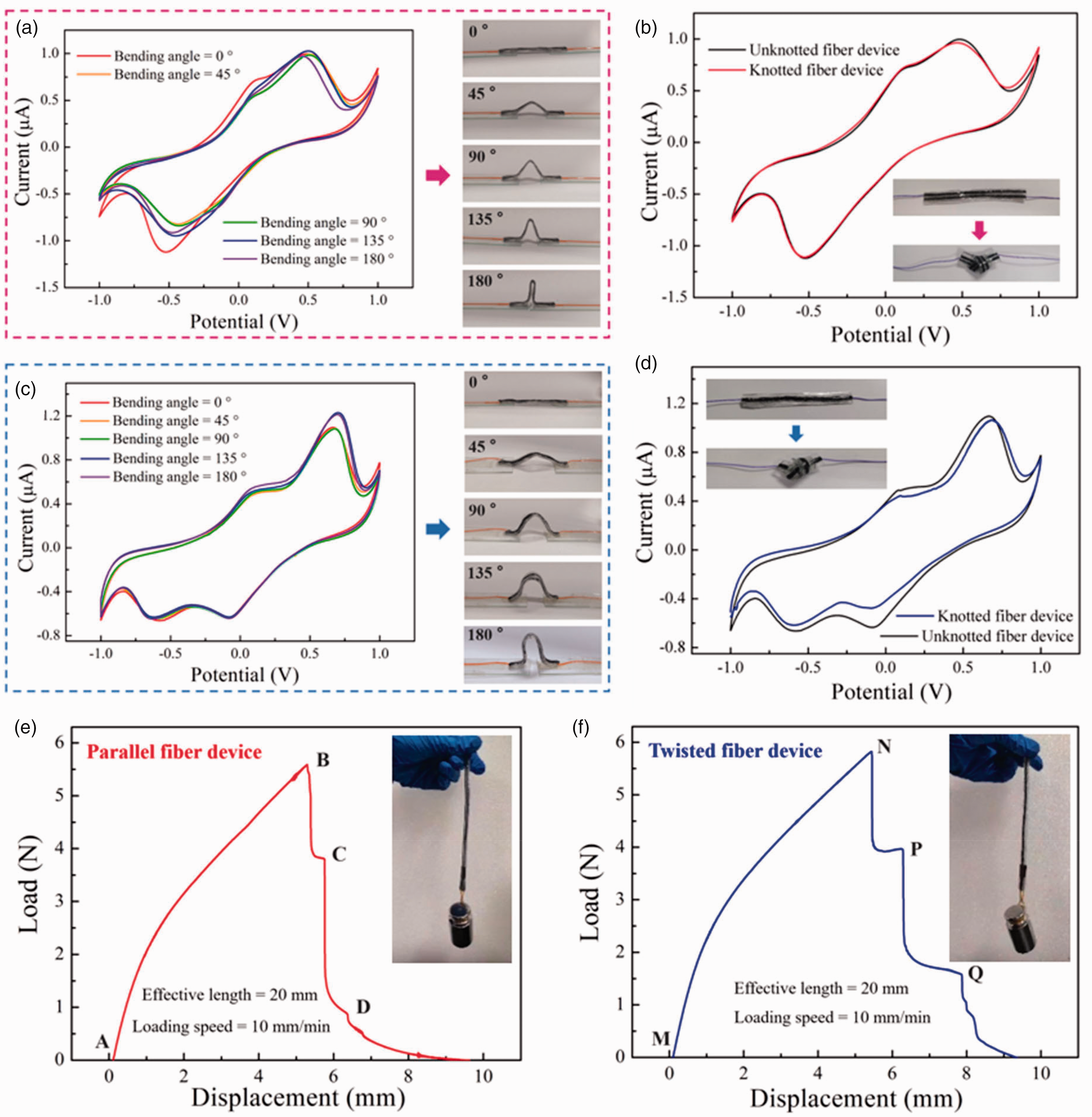
Cyclic voltammetric curves as well as optical images of the (a) parallel and (c) twisted fiber devices bending at different angles, respectively; cyclic voltammetric curves as well as optical images of the (b) parallel and (d) twisted fiber devices before and after knotting, respectively; load–displacement curves as well as weight hanging optical images of the (e) parallel and (f) twisted fiber devices, respectively.
Figures 5(e) and (f) exhibit the load–displacement curves of the parallel and nano-MnO2 twisted fiber supercapacitors (effective length of 20 mm), respectively, and the optical images in the figures show excellent mechanical properties of the two fiber devices by lifting a 250 g weight (length of 15 cm). From the load–displacement curve of the nano-MnO2 parallel fiber supercapacitor in Figure 5(e), the parallel fiber device is stretched gradually from A to B under a loading speed of 10 mm/min, 31 obtaining the extreme displacement of 5.3 mm, and thus B is considered as the breaking point, and the breaking load is 5.6 N. Afterwards, the fiber devices begin to break, and the whole fracture process can be divided into three parts 32 : during the B to C process, the outermost PDMS sealing layer begins to elongate and fracture gradually until it breaks completely at point C; then the LiCl gel electrolyte starts to break and breaks completely until point D; then the two parallel nano-MnO2 fiber electrodes are stretched constantly after point D, finally making a breakage until the fiber device is pulled apart into two separate parts. During the whole stretching process, the maximum displacement of the parallel fiber supercapacitor is 9.5 mm, indicating excellent tensile performance. On the other hand, the load–displacement curve of the nano-MnO2 twisted fiber supercapacitor in Figure 5(e) presents a similar shape to that of the parallel device, which implies they have the same tensile fracture mechanism. However, because of the unique arrangement of electrodes in the nano-MnO2 twisted fiber supercapacitors, the fiber electrodes begin to break at a larger displacement (around 7.9 mm) than in the parallel one (around 6.4 mm), which would protect the devices from damage more effectively under large-tensile situations, suggesting better structural stability in practical application.
Conclusions
In summary, this work proposes a reliable method to fabricate nano-MnO2/CMC fiber electrodes via binary coaxial wet spinning technology and assemble them into different nano-MnO2 fiber supercapacitors. Thereinto, the active materials, nano-MnO2, are protected by a CMC layer effectively in the fiber electrode, avoiding a short circuit between the fiber electrodes on the basis of requisite ion exchange. The obtained parallel as well as twisted nano-MnO2 fiber supercapacitors exhibit excellent electrochemical performance: the parallel nano-MnO2 fiber supercapacitor reaches the CL of 19.7 μF/cm as well as EL of 0.0027 μWh/cm at current density of 0.5 μA/cm, and PL of 1.49 μW/cm at 5 μA/cm; the twisted nano-MnO2 fiber supercapacitor achieves the CL of 49 μF/cm as well as EL of 0.0053 μWh/cm at current density of 0.5 μA/cm, and PL of 1.0 μW/cm at 5 μA/cm. Furthermore, the two fiber supercapacitors both present good softness and tensile properties, which can maintain excellent electrochemical performance under bending or knotting situations, showing broad prospects in the smart wearable field. Therefore, this strategy could be extended to flexible metal oxide fiber electrodes and fiber supercapacitors in the future.
Supplemental Material
sj-pdf-1-trj-10.1177_00405175231181088 - Supplemental material for Different assembled nano-MnO2 fiber supercapacitors applied for smart wearable clothing
Supplemental material, sj-pdf-1-trj-10.1177_00405175231181088 for Different assembled nano-MnO2 fiber supercapacitors applied for smart wearable clothing by Qi Wang, Mengfan Wang, Jiali Sun, Xiaolin Zhang, Weichun Chen, Xichen Yu and Wei Fan in Textile Research Journal
Footnotes
Declaration of conflicting interests
The author(s) declared no potential conflicts of interest with respect to the research, authorship, and/or publication of this article.
Funding
The author(s) disclosed receipt of the following financial support for the research, authorship, and/or publication of this article: This work was supported by the Research Fund for the Doctoral Program of Xi'an Polytechnic University (No. BS202053), the Science and Technology Planning Project of Beilin District in Xi'an City of Shaanxi Province (No. GX2205), the Scientific Research Program Funded by Shaanxi Provincial Education Department (No. 22JK0402) and the Textile Vision Basic Research Program of China (No. J202110).
Supplementary data
Supplementary data to this article can be founded in the Electronic Supplementary Information.
References
Supplementary Material
Please find the following supplemental material available below.
For Open Access articles published under a Creative Commons License, all supplemental material carries the same license as the article it is associated with.
For non-Open Access articles published, all supplemental material carries a non-exclusive license, and permission requests for re-use of supplemental material or any part of supplemental material shall be sent directly to the copyright owner as specified in the copyright notice associated with the article.