
Abstract
The traditional tension control method with tension as the control target is to uniformly control multiple warp beams and has low control accuracy. Simultaneously, it is difficult to install an independent sensor for a single warp beam to achieve a closed-loop control, due to the space limitation. Combined with the theoretical model, this paper proposes a novel method to achieve the closed-loop unwinding tension control of warp beams by taking the unwinding length as the control target and using the self-developed turns measuring device. First, the dynamic model between different factors and unwinding tension was established in this study. Furthermore, the influence of unwinding radius, unwinding speed and winding density on the tension was investigated to clarify the fluctuation mechanism. Based on these, simulation experiments were conducted for verifying the control effect of the proposed method. The results showed that the proposed single warp beam unwinding tension control method can achieve constant tension throughout the unwinding process, which is superior to the empirical open-loop control method that adjusts the tension according to the linear proportional change of the braking torque. Meanwhile, it has the similar control effect as the ideal closed-loop tension control method, maintaining stability under different reference tensions and disturbances. In addition, the proposed multiple warp beams unwinding tension control method also outperformed the traditional unified tension control method. Our measuring device can be easily installed on the single warp beam for control, resulting in consistent tension between multiple warp beams. Therefore, the proposed methods have a certain control effect and application value.
In recent years, in order continuously to improve the internal and external quality of the fabric, it is necessary to maintain the consistency of yarn tension for each thread, sheet, and beam from winding to weaving.1,2 Therefore, tension control is required at each stage, such as the winding of the reel yarn, the warp beam, and the weaving beam.3–6 Sizing is a crucial process in the weaving preparation stage that guarantees weaving quality and efficiency. 7 Usually, the sizing machine adopts multisection control for warp tension. Among them, the warp beam unwinding area is regarded as the first control area. The warp yarns are not actively guided by the main transmission component. Here, a commonly employed method involves the combination of passive warp beam delivery and friction-based warp beam braking. 8 However, tension can be affected by various factors during the unwinding process of the warp beams, including significant parameter variations and disturbances.9–12 The mutual coupling among these factors can easily cause the tension to deviate from the reference value and produce fluctuations. The uniformity of unwinding tension in the warp yarns between each warp beam is crucial to maintain consistent elongation throughout the entire warp yarn. It minimizes the potential effects of tension fluctuations on the quality of sized yarns and production efficiency of the loom.13,14 Therefore, the unwinding tension control for warp beams on the sizing machine has more important significance.
In general, the control system for unwinding tension of warp beams achieves constant tension by using tension or speed as the control objective. 15 Tong 16 took warp tension and elongation as the control objectives and analyzed their composition in different zones on the sizing machine. The tension system has been precisely regulated by a mechanical device, electric sensor, and frequency conversion speed regulator controlled by a programmable logic controller (PLC). Lei et al. 17 adopted warp tension as the control objective and used the neural network control algorithm to achieve constant tension control. The simulation results showed that the transition time of the system based on multineuron PID control was about 0.5 s, and the system was stable with a better control effect. Liu and Bing 18 used the warp unwinding tension as the control objective and adopted the fuzzy-PI controller for the parameter self-adjusting to enhance control accuracy and disturbance resistance. The results indicated that the controller can efficiently and automatically control tension with faster dynamic response and better robustness. Besides this, Yu and Zhang 19 analyzed the yarn tension during the unwinding of the single-row interwound warp beam in a static state. The main factor affecting the yarn tension variation was the frictional resistance between the beam head and the bearing. Ru et al. 20 used equipment such as sheet yarn tension sensors, dynamic resistance strain gauges, and optical oscilloscopes to test the dynamic unwinding tension of warp beams. It was found that the factors affecting unwinding tension are quite complex. Zhang 21 established the theoretical relationship between unwinding tension, radius and warp beam weight to analyze the root cause of tension differences under different warp unwinding methods. At the same time, studies22,23 on other related unwinding processes have shown that unwinding speed and yarn characteristics are also key influencing factors of unwinding tension fluctuations.
Analysis from present literature showed that most studies have focused on developing new controllers without thoroughly analyzing the dynamic models and influence factors of the warp beam unwinding tension. In addition, the fluctuation mechanism of the unwinding tension has been largely ignored. More importantly, through on-site investigations in relevant textile enterprises, it was found that PID control is still the most commonly used controller, which is easy to implement and has strong robustness. Meanwhile, during the actual unwinding process of the warp beam, the control effect of the unwinding tension control scheme with tension or speed as the control objective is not satisfactory. The tension sensor can only detect the overall warp sheet tension of multiple warp beams (MWBs) to regulate them uniformly, but it cannot accurately control each individual warp beam. Due to differences in warping production, braking mechanisms and transmission components, the tension state of each warp beam must be different, so the tension of the entire warp yarn is still uneven after control. Thus, there will be more uneven residual yarn amounts on each warp beam at the end of the unwinding process, due to the change of the unwinding length caused by tension fluctuations. This phenomenon leads to a waste of resources. Next, Ma et al. 24 proposed a solution to this problem by installing an independent tension sensor for each warp beam. The unwinding tension of each warp beam is controlled in real time based on the measured value of each tension sensor, ensuring a constant tension is maintained during the yarn unwinding. However, as the relatively short distance between the warp beams and the guide rollers, and the small space between each warp beam, implementing this method in actual factories can be challenging and expensive.
Therefore, in order to solve the aforementioned problems, this paper proposes achieving constant unwinding tension of the warp beams with unwinding length as the control objective. A self-developed device to measure the number of turns for each warp beam is used to monitor the actual unwinding length in real time. The real-time tension is calculated by a derived theoretical model. The method can install an independent detection device for a single warp beam (SWB) and control it individually. By monitoring its unwinding length in real time, the consistency of the unwinding status of each warp beam is ensured. On the basis of achieving constant tension on a SWB, the uniformity of MWBs unwinding tension is improved, thereby minimizing the generation of residual yarn during the unwinding process. In addition, the measuring device is easier to install and lower cost than the tension sensor.
The rest of this paper is organized as follows. The second section establishes dynamic models of the warp yarn and warp beam during the unwinding process on the sizing machine, and clarifies the tension fluctuation mechanism by discussing the influence and coupling effect of different factors on unwinding tension. In the third section, the control strategy is proposed by separately controlling the unwinding length and the average unwinding length to achieve the constant tension of the SWB and MWBs. In the fourth section, simulations are conducted to verify the effectiveness of proposed methods by comparing the results with traditional tension control methods. The final section is the conclusions.
Dynamic modeling and mechanism of tension fluctuation
The sizing yarn process is shown in Figure 1, which includes four main stages: unwinding, sizing, drying, and winding. 25 First, the warp sheets (multiple warp yarns) are released from several warp beams and transferred to the slurry tank to absorb the slurry. Afterwards, they enter the drying room to undergo the drying process and are ultimately wound onto a single loom beam. Each stage involves the warp yarns passing through several rollers, facilitating the transformation of the warp sheets into their final form. From the sizing to the winding, the movement and tension control of the warp yarns are actively driven by the main transmission components. However, in the unwinding area, the warp yarns are not actively guided by these components. Instead, a common approach involves a combination of passive warp beam delivery and friction-based braking.
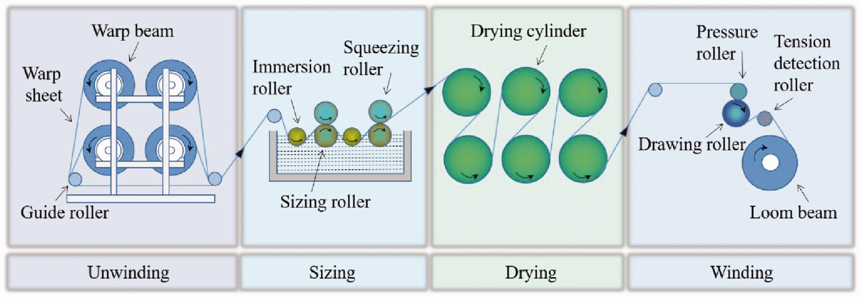
Sketch of sizing yarn process.
The unwinding process consists of MWBs and guide rollers. The cross-sectional view of the SWB unwinding process is shown in Figure 2. Due to the speed difference between the warp beam and guide roller, the warp sheet creates tension and continuously unwinds from the warp beam. 26 The braking torque of the warp beam is adjusted by the brake to achieve the desired unwinding speed and tension.
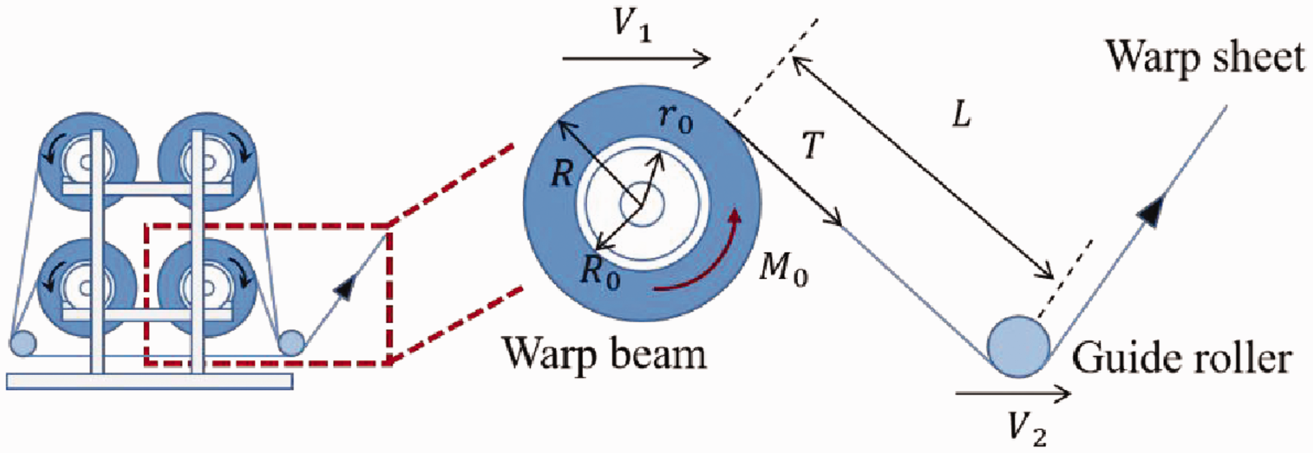
Cross-sectional view of single warp beam (SWB) unwinding process.
Dynamic modeling of the warp yarn
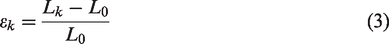
The warp yarn is often regarded as an excellent elastic material. According to Hooke's law, the unwinding tension of the warp yarn is proportional to its deformation rate within the range of elastic deformation.
27
The dynamic model of the warp yarn can be expressed as:
It provides insight into the underlying causes of tension and obtains a simple relationship between tension and speed difference. However, the dynamic model of the actual warp yarn deviates from an ideal spring model. 28 Therefore, this paper derives the dynamic model of the warp yarn based on the law of mass conservation, and conducts a thorough investigation of the coupling relationship between the tension and speed.
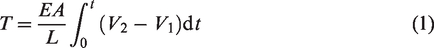
The law of mass conservation refers to the rate of mass accumulation in a control volume, which is equal to the sum of the net rate of mass inflow into the control volume and the rate of mass of generation within the control volume. 29 In general, the distance between the warp beam and the guide roller remains constant, so it constitutes a typical mass flow system. The linear density of the warp yarn refers to its mass per unit length. The schematic diagram before and after warp stretching is shown in Figure 3. The warp yarn cross-sectional area experiences only minor changes that can be ignored.
The schematic diagram of yarn before and after stretching.
Mass conservation of the warp yarn before and after stretching, so:

The stretch rate of the warp yarn is:
Thus:
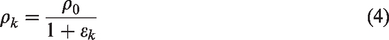
According to the law of mass conservation:

As the stretch rate
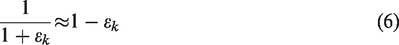
Combined with equations (1), (4) and (6), equation (5) can be simplified to:

Therefore, the warp yarn dynamics model derived from the law of mass conservation can be written as follows:

Compared with equation (1) and equation (8), equation (8) more accurately describes the coupling relationship between tension and speed. The unwinding tension of the warp yarn is not only associated with the speed of the warp beam and guide roller, but also with the distance between the two rollers. Greater speed differences result in higher tension, whereas shorter lengths facilitate faster attainment of constant tension.
Dynamic modeling of the warp beam
In the unwinding process of the warp beam, unwinding tension is influenced by many factors, rendering its control relatively intricate. 30 Consequently, it is necessary to conduct a dynamic analysis of the warp beam unwinding process.
According to Newton's second law of rotational motion, the dynamic moment equation of the warp beam unwinding process is:

Due to the centripetal pressure, the winding density of the yarn in the inner layer of the warp beam is greater than that of the outer layer. While adjustments are made during warping to ensure consistency, there may still be slight differences. Assuming that the warp beam unwinds
The frictional resistance torque is expressed as follows:

At any time,

Thereinto:

So, the rate of change of
The radius of the warp beam decreases due to the warp yarn continuously releasing into the unwinding process.
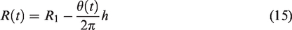
Equation (16) can be obtained by calculating the derivative of (15):
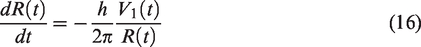
The rate of change of

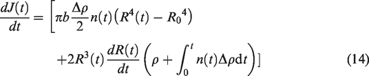
Therefore, Equation (9) can be written as:
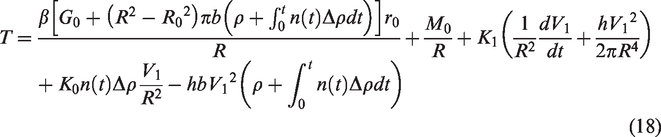
As shown in equation (18), the unwinding tension control system is nonlinear, multi-interference, and time-varying. The most critical factors that affect constant tension control are speed disturbances and changes in radius. In addition, the unwinding tension is also related to the winding density and the dynamic friction coefficient, among other factors.
Mechanism of unwinding tension fluctuation
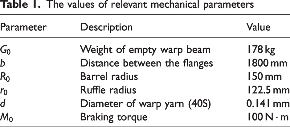
According to equation (18), the mechanism of tension fluctuation was studied. The individual influence and coupling effect of unwinding radius, unwinding speed and winding density on tension were discussed. The values of relevant mechanical parameters are shown in Table 1.
The values of relevant mechanical parameters
The influence of unwinding radius on unwinding tension is shown in Figure 4. In Figure 4,
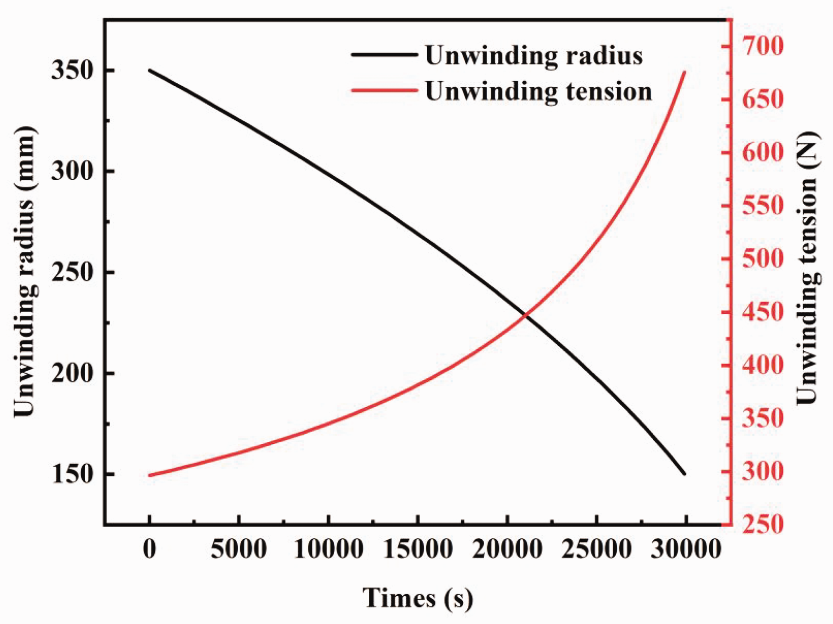
Influence of unwinding radius on unwinding tension.
The influence of unwinding speed on unwinding tension is illustrated in Figure 5. In Figure 5,
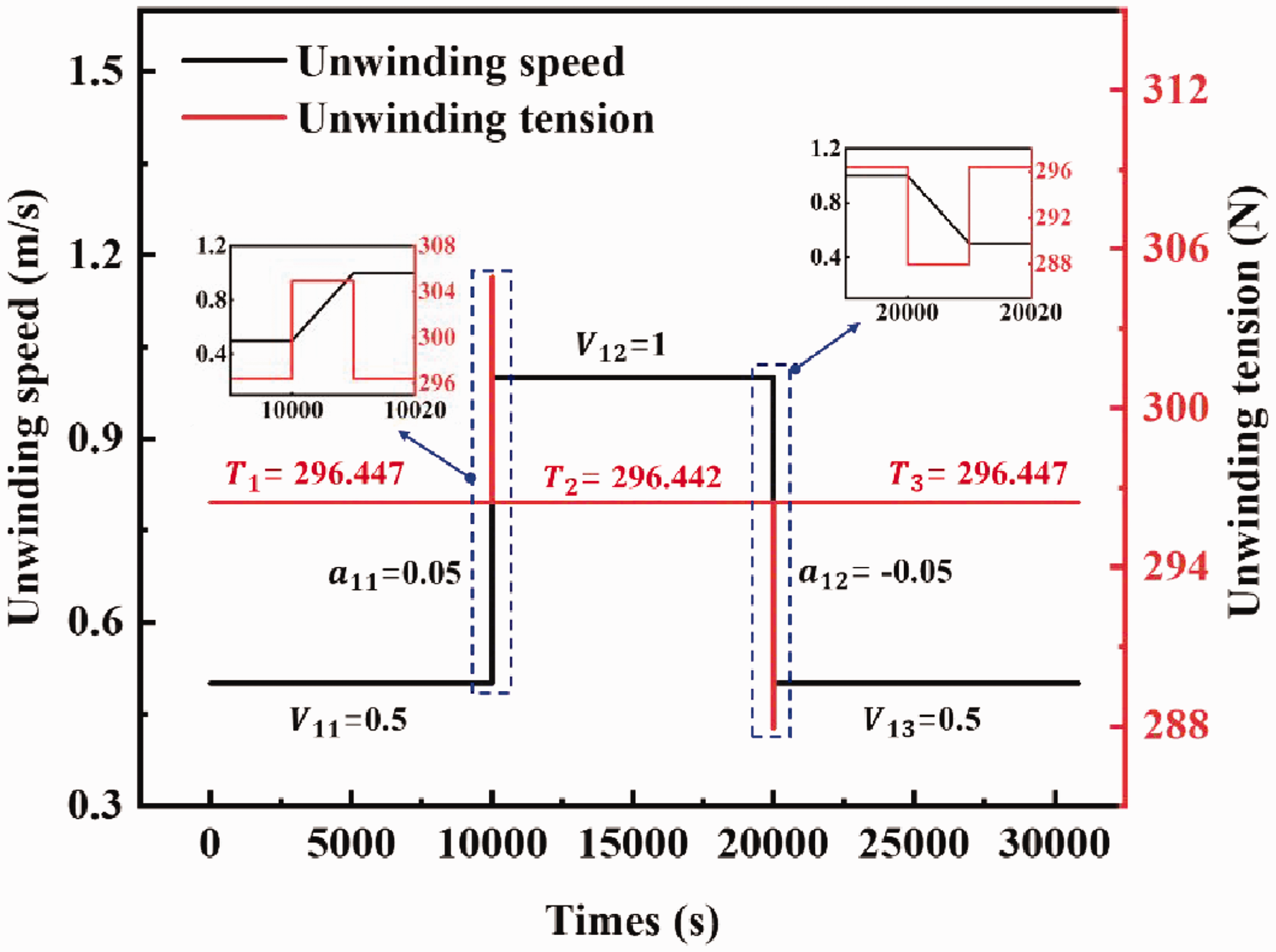
Influence of unwinding speed on unwinding tension.
The influence of winding density on unwinding tension is depicted in Figure 6. In Figure 6,
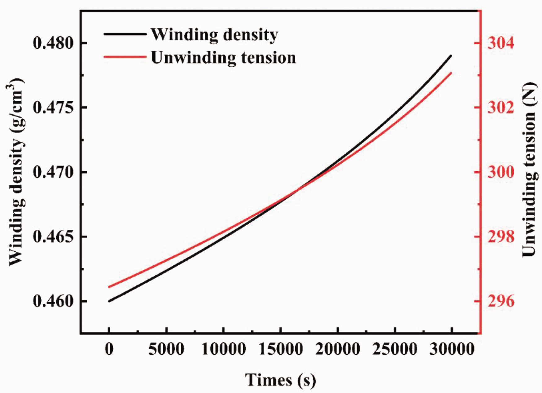
Influence of winding density on unwinding tension.
The coupling effect among various factors on unwinding tension is shown in Figure 7. In Figure 7,
Coupling effect between various factors on unwinding tension.
Control design
Control objective
The traditional tension control scheme with either tension or speed as the control objective detects the overall warp sheet tension through the tension sensor to control MWBs uniformly. This method has low control precision and the installation of individual tension sensors for SWB is not easy to implement. Therefore, we propose to use the unwinding length as the control objective and design the turns measuring device to realize the constant tension control of the SWB and MWBs on the sizing machine. According to the dynamic model of the warp yarn (equation (8)), the guide roller speed
Control method
PID is a control method that estimates past, present, and future information, which consists of a PID controller and a controlled object. The PID controller is widely used in industry because of its simple structure, good robustness and easy implementation. 31 Therefore, this paper also adopts the PID controller to achieve constant tension by controlling the unwinding length of the warp beam.
The PID controller is a linear controller that calculates the difference 

The proportional gain
The constants
Control system
The MWBs are composed of several SWBs. The schematic diagram of MWBs unwinding tension control system is shown in Figure 8. The unwinding tension control system can realize real-time detection and tension control of the warp beams without modifying their motion system. The system includes the warp beams motion system, computer, PID controller, measuring device (photoelectric sensors), brake, and driver board.
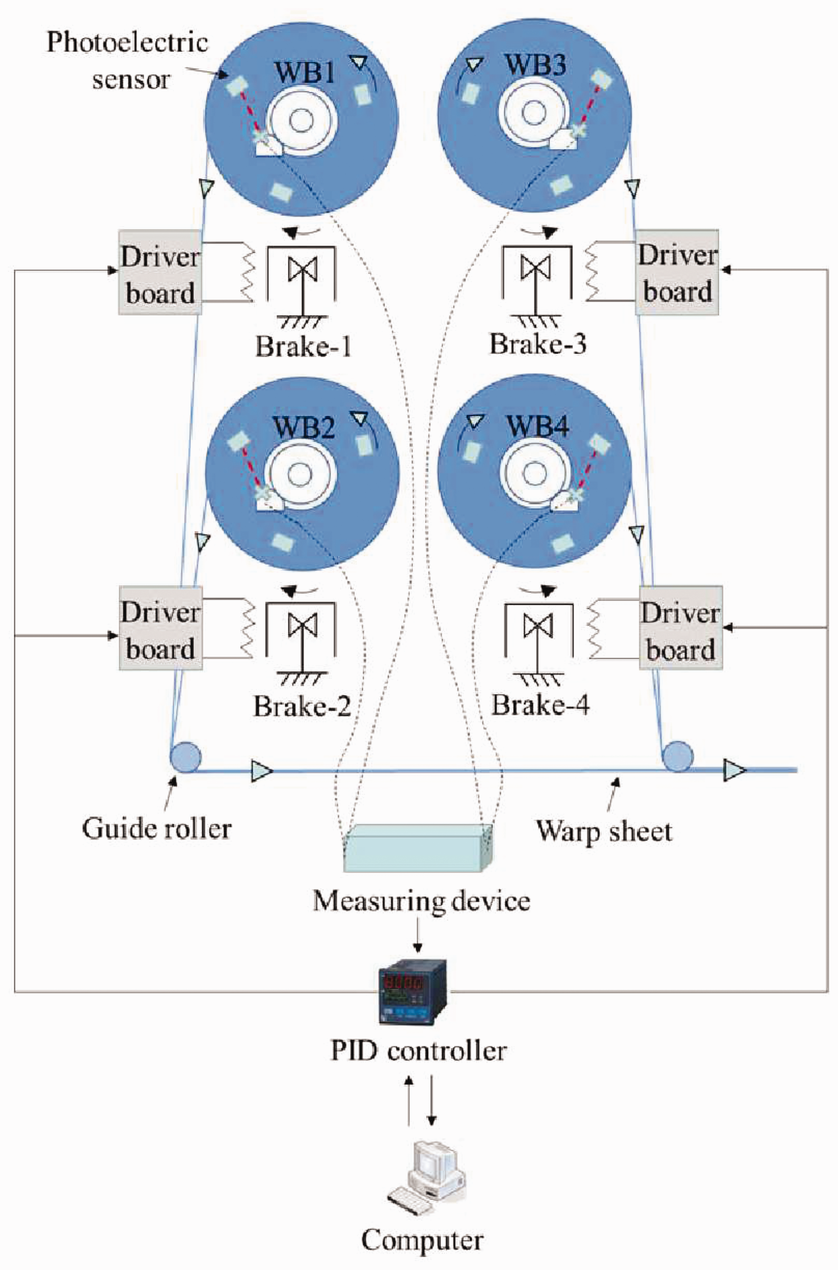
The schematic diagram of multiple warp beams (MWBs) unwinding tension control system.
The computer sends commands through peripheral and software to set the guide roller speed and the warp beams unwinding tension. Then, it obtains the control objective value of the unwinding length through the built-in program, using the dynamic model of the warp yarn (equation (8)). The computer also assumes the monitor function of the feedback signal.
The PID controller is the core part of the tension control system. It receives signals from the computer and the measuring device, and processes them to achieve the desired control. The signal from the measuring device should be calculated and compared with the objective value of the unwinding length after filtering processing. Then, the PID controller sends a control signal to drive the brake by the driver board after judging whether unwinding length is within the range of the preset value.
The main component of the measuring device is the photoelectric sensor, which is used to detect the total number of turns of each warp beam in real time and transmit the information to the PID controller. The real-time unwinding length of the warp beam can be calculated by equation (21), where 
After the drive board receives the control signal from the PID controller, it drives the brake to adjust the braking torque. If the actual value of the unwinding length is different from the preset value, the drive board drives the brake to increase or decrease the braking torque to lower and add unwinding length. Meanwhile, the total number of turns of each warp beam is detected and sent to the PID controller as a feedback signal. In this way, a closed-loop control system is constructed using the PID control strategy.
Control scheme
In order to achieve uniform tension, alignment and winding density of the warp yarns during warping and sizing, the total number of the warp yarns required for the fabric is divided into MWBs in sizing. However, in the actual production process, there will be certain differences between the warp beams after the traditional tension control method. Consequently, according to the unwinding tension control system, we propose unwinding tension control schemes for both SWBs and MWBs.
The SWB unwinding tension control scheme is shown in Figure 9. To ensure the stability of the system, a closed-loop adjustment is employed. The preset unwinding length is taken as the input of the sizing machine. The actual unwinding length of the loop is the feedback value, which is calculated by equation (21). The PID controller is designed for controlling the error of the preset and actual unwinding length
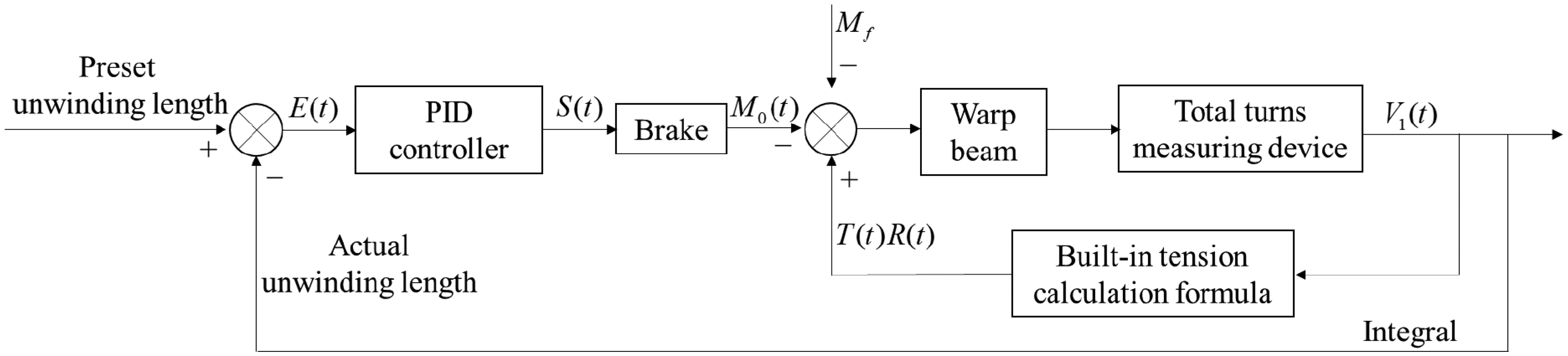
The single warp beam (SWB) unwinding tension control scheme.
On the basis of the above, we have proposed a MWBs unwinding tension control scheme. The MWBs unwinding tension control scheme is shown in Figure 10. The actual average unwinding length of MWBs is used as the reference value to adjust the unwinding difference between them. Each warp beam uses its own PID unwinding tension control system to keep the actual unwinding length consistent with the average unwinding length. This further reduces the interference of other factors on the tension and results in better uniformity of warp sheet tension in MWBs.
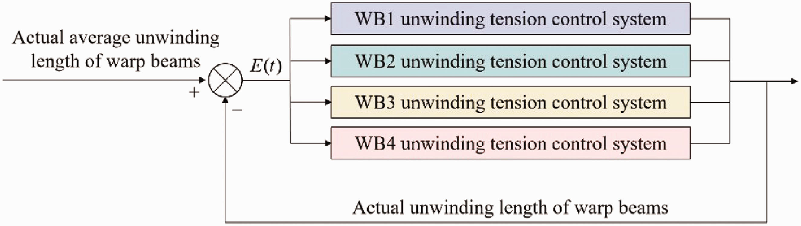
The multiple warp beams (MWBs) unwinding tension control scheme.
Simulation and result analysis
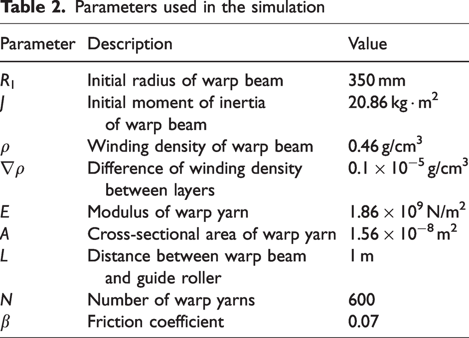
The Simulink Toolbox, as an essential component of the Matlab software, is widely utilized in the analysis of control systems.36–38 It provides an integrated environment encompassing dynamic system modeling, simulation, and comprehensive analysis. According to the differential equations, simulation models for SWB and MWBs tension control system have been established to verify the rationality of the schemes and control effect. The simulation parameters mainly derive from relevant references and actual parameters that are close to the real state, as presented in Table 2. The optimized PID control parameter combination where
Parameters used in the simulation
Simulation result and analysis of SWB
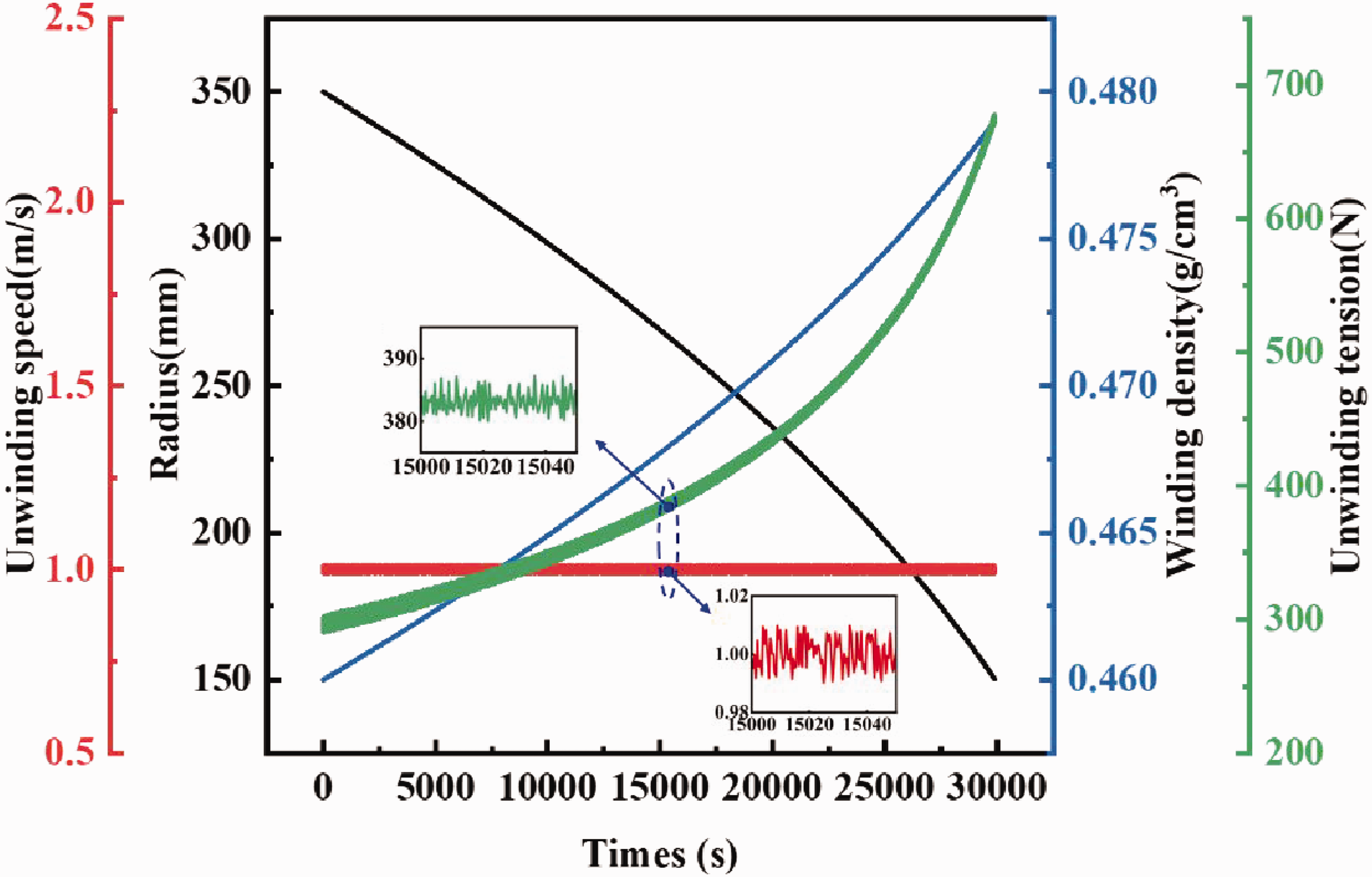
Simulations were run for studying the tension response in the steady-state stage. The speed of the guide roller is set as 1 m/s. The reference unwinding tension is 348 N. Therefore, the unwinding speed of the warp beam is 0.98 m/s by formula calculation, that is, the preset unwinding length is
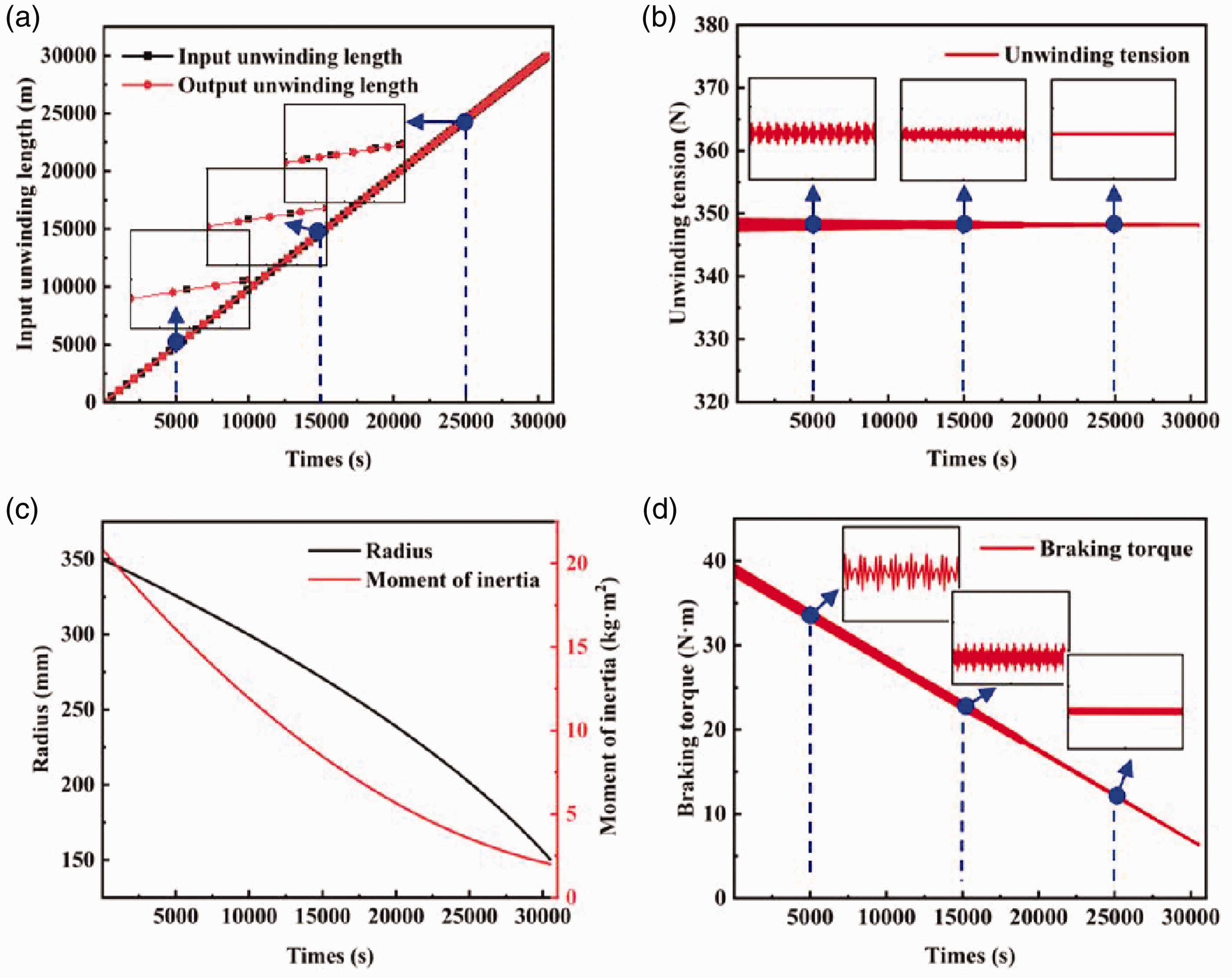
Simulation results of single warp beam (SWB) unwinding tension control. (a) Unwinding length; (b) unwinding tension; (c) radius and moment of inertia and (d) braking torque.
In Figure 11(c) and (d), it can be observed that as the unwinding length increases, the radius and moment of inertia of the warp beam gradually decrease. The braking torque also decreases after the unwinding tension reaches equilibrium to compensate for the effect of radius and moment of inertia changes on the unwinding tension. The braking torque is constantly adjusted to keep the constant tension, so the braking torque has the same fluctuation law as the tension. The values of unwinding length, unwinding tension and braking torque at 10,000 s, 20,000 s, and 30,000 s are presented in Table 3.
Values of unwinding length, unwinding tension and braking torque at different times
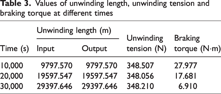
Multiple groups of simulation experiments were conducted with the speed of the guide roller remaining constant, and the reference unwinding tension was set at 435 N and 522 N. Similarly, the preset unwinding length was determined to be
Unwinding tension response of different references unwinding tension. (a) 435 N reference unwinding tension; and (b) 522 N reference unwinding tension.
Values of the magnitude of tension fluctuation and the average tension under different reference tensions and times
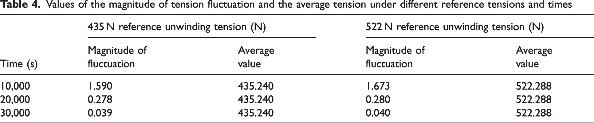
Therefore, the SWB unwinding tension control scheme has shown good control performance under different reference unwinding tensions and real-time changes in the radius, moment of inertia, and winding density of the warp beam. Moreover, the simulation environment closely resembles the actual production environment, as the unwinding tension exhibits very little fluctuation around a constant value.
The traditional unwinding tension control methods are classified into open-loop and closed-loop unwinding tension control methods (T-OL method and T-CL method), both of which take tension as the control target. The T-OL method keeps the unwinding tension constant by changing the braking torque in a linear proportion, as illustrated in Figure 13. The starting and ending braking torques are estimated from the diameter of the warp beam at the beginning and end. Thus, the tension at the beginning and end is controlled at the reference value, but the tension cannot be precisely controlled in the middle unwinding process. Moreover, the braking torque will not change to adjust in time when a disturbance occurs. Therefore, the control effect of the T-OL method is poor compared with the proposed method.
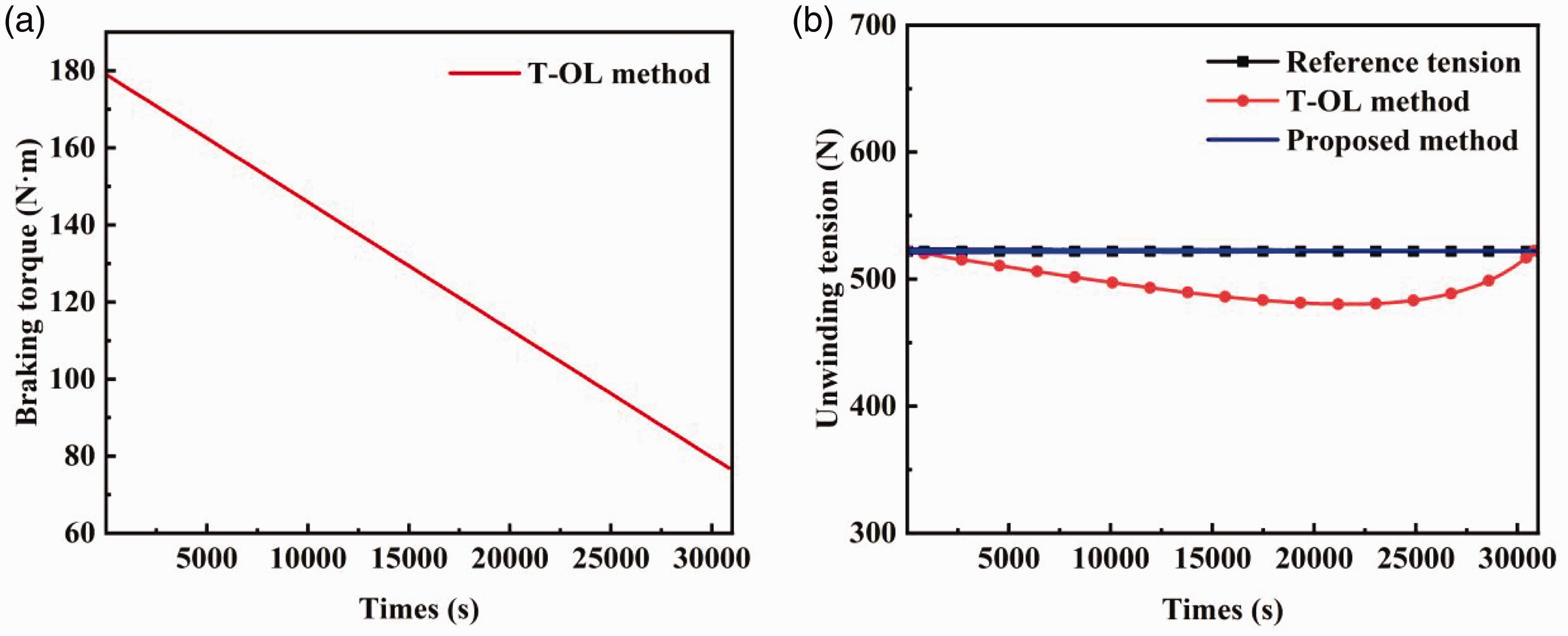
T-OL method for single warp beam (SWB). (a) Braking torque; and (b) unwinding tension.
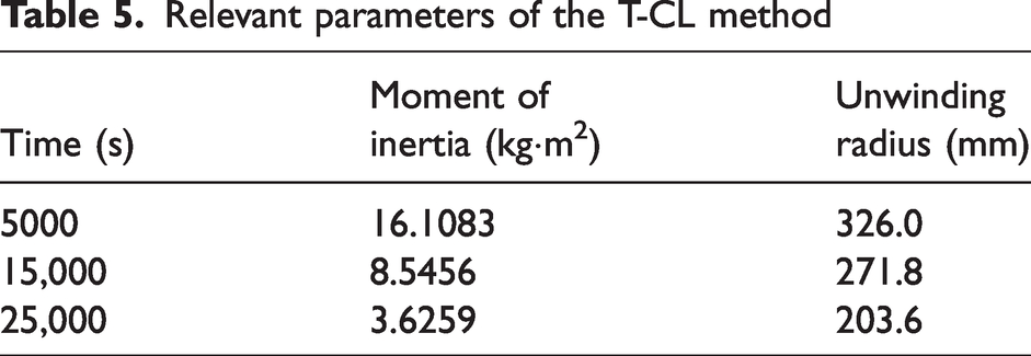
However, both the T-CL method and the proposed method can form a closed loop. The braking torque will be adjusted continuously with the change of the tension to keep it constant, and it also has a certain anti-interference ability. Typically, the T-CL method uses a transfer function for modeling analysis. In a short time, the changes in the moment of inertia and the unwinding radius of the warp beam can be ignored. The relevant parameters of the T-CL method are shown in Table 5.
Relevant parameters of the T-CL method
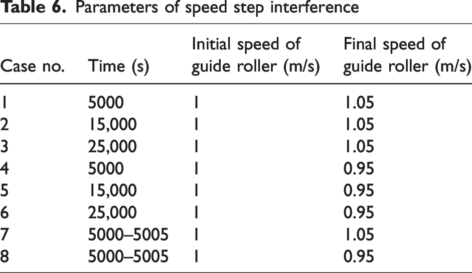
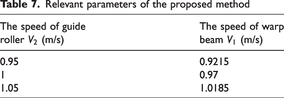
In order to compare the control effect of the T-CL method and the proposed method, the speed step interference introduced by the guide roller during the warp beam unwinding within a certain moment are shown in Table 6. The preset unwinding tension is 522 N. According to equation (8), we can get the corresponding warp beam unwinding speed in the proposed method (Table 7). The preset unwinding length is
Parameters of speed step interference
Relevant parameters of the proposed method
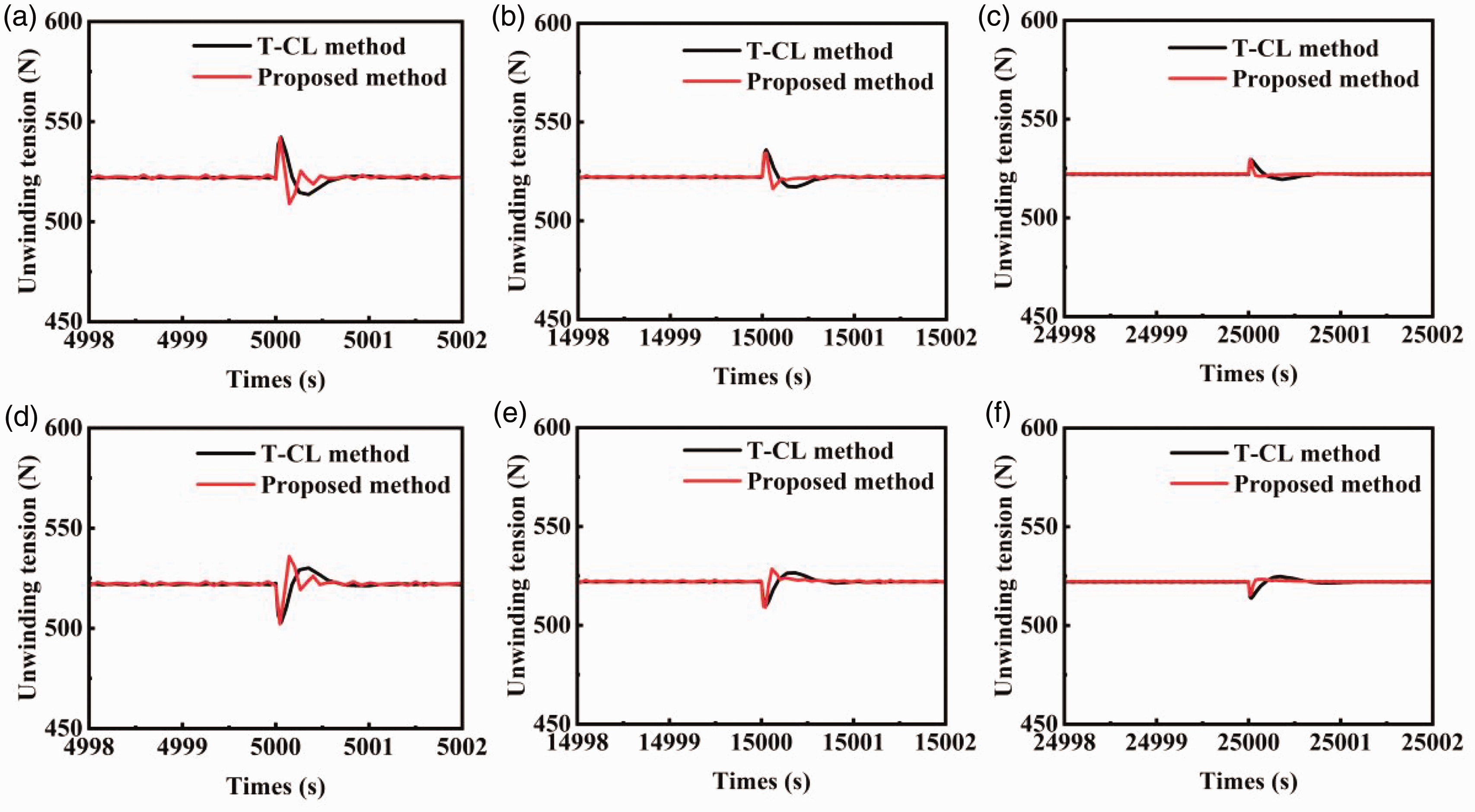
Effect of speed step interference in the T-CL method and proposed method. (a) Case 1; (b) case 2; (c) case 3; (d) case 4; (e) case 5; and (f) case 6.
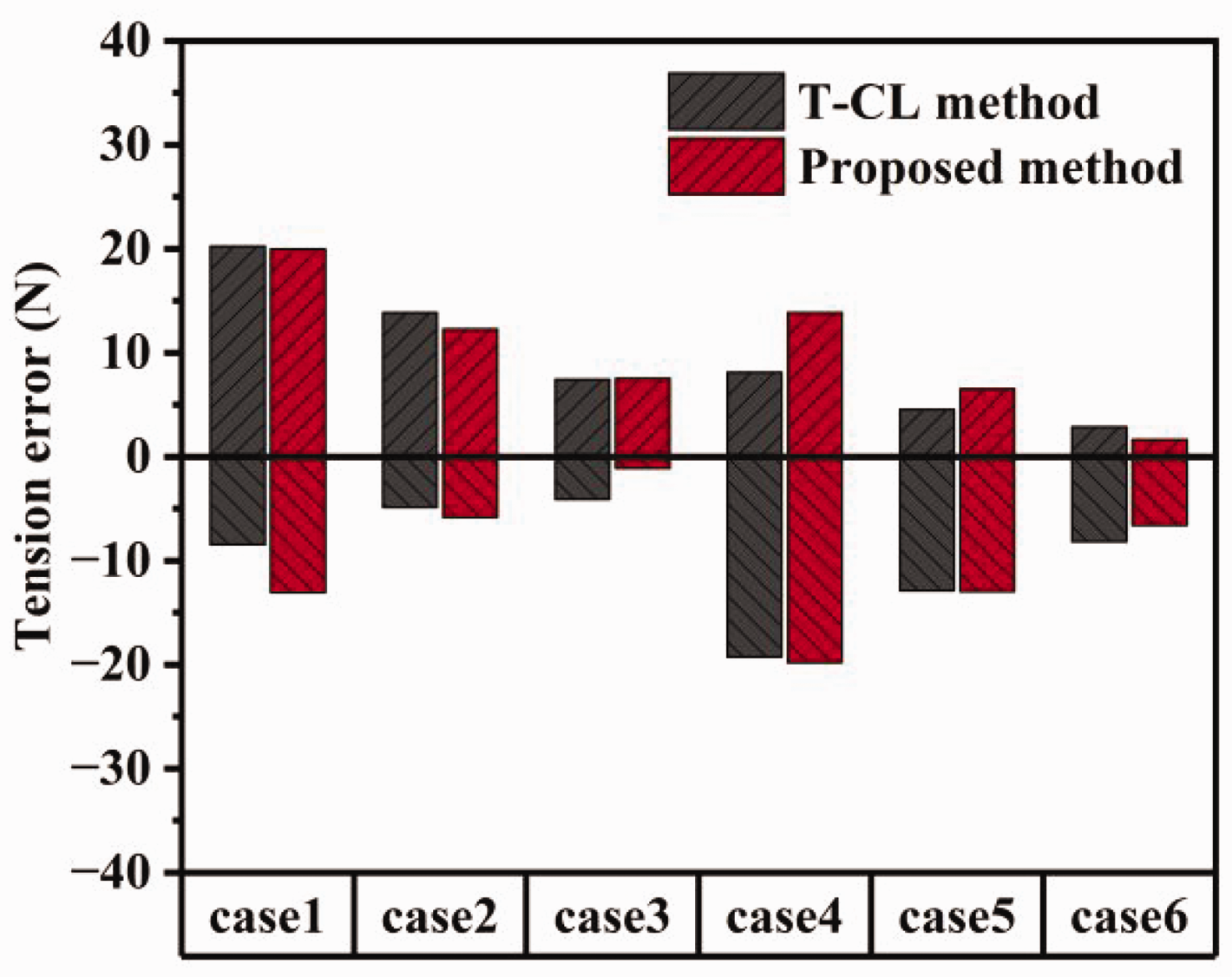
Unwinding tension errors in six cases.
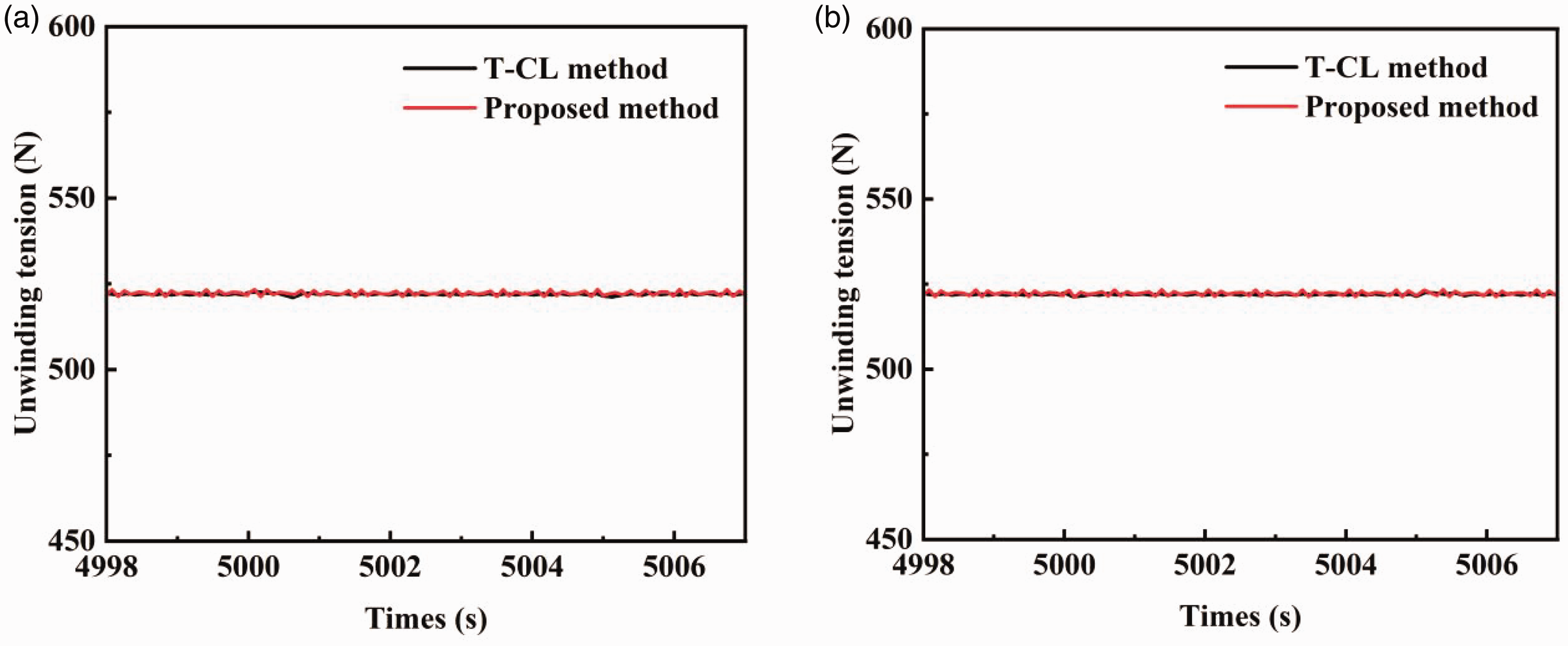
Effect of slow speed change in the T-CL method and proposed method. (a) Case 7; and (b) case 8.
In Figure 14(a–c) and (d–f), when the speed of the guide roller is increased from 1 to 1.05 m/s or decreased from 1 to 0.95 m/s, the sudden changes in speed cause fluctuations in the unwinding tension. As the unwinding time increases (the unwinding radius decreases), the influence of the step disturbance becomes smaller. In our control method, a unique unwinding speed for constant unwinding tension is maintained at each guide roller speed. By controlling and monitoring the unwinding length at this time, the unwinding tension fluctuations of the proposed method return to stability within 0.5 s, which is faster than the T-CL method.
The peak values of the unwinding tension overshoot and downregulation in six cases are presented in Figure 15. When the unwinding radius is large (case 1), the fluctuation peak of the proposed method is larger than that of the T-CL method. For small unwinding radius (case 6), the proposed method is better than the T-CL method. Thus, the proposed method has a similar control effect to the T-CL method. Under normal conditions, the speed of the guide roller changes slowly. The effect of a slow speed change in the T-CL method and proposed method is shown in Figure 16, which reveals that there are no significant fluctuations in the unwinding tension.
However, the T-CL method can only uniformly detect the overall yarn tension and lacks independent detection and control of the SWB. Due to space and cost issues, it is not practical to install independent tension sensors for each warp beam. The measuring device used in the proposed method is able to detect accurately the number of unwinding turns of each warp beam to monitor the real-time unwinding length and finally realize the independent tension control of the SWB. More importantly, the measuring device is less expensive and easier to install than a tension sensor.
In summary, it can be concluded that the constant unwinding tension control of the SWB can be achieved by controlling the unwinding length. The proposed method exhibits a superior control effect than the T-OL method. At the same time, it can achieve the similar control effect as the T-CL method and is easier to implement and of lower cost.
Simulation result and analysis of MWBs
Generally, due to differences in weight, braking effect, and frictional force of each warp beam, there will also be differences in the unwinding state between MWBs. The parameters of MWBs at a certain moment (15,000 s) are shown in Table 8.
Parameters of MWBs at a certain moment (15,000 s)
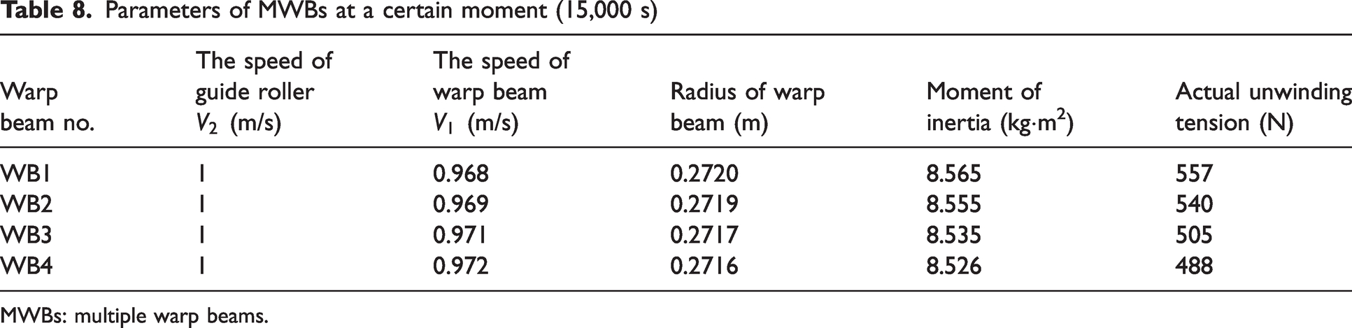
MWBs: multiple warp beams.
In our proposed method, the actual average unwinding length of MWBs is used as the reference value to adjust the unwinding difference between them. The simulation results of MWBs unwinding tension control are shown in Figure 17. As can be seen in Figure 17, the unwinding length and unwinding tension of each warp beam can be consistent with the reference value after control. Due to differences in the braking effect and other aspects, the unwinding tension value of each warp beam has slight fluctuations to varying degrees.
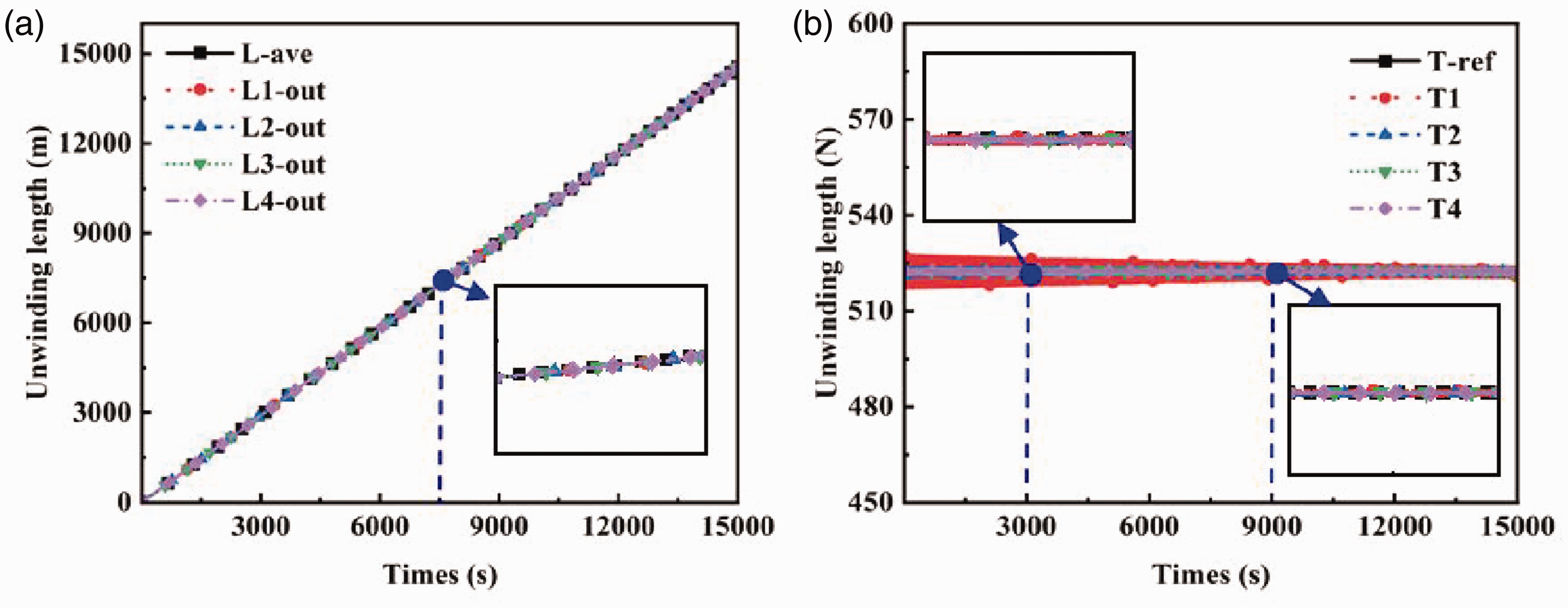
Simulation results of multiple warp beams (MWBs) unwinding tension control with proposed method. (a) Unwinding length; and (b) unwinding tension.
The comparison of the control effect between the traditional unified tension control method (T-U method) and the proposed method for MWBs unwinding tension is presented in Tables 9–11. The T-U method aims to control each warp beam uniformly by the difference between the detected tension and the reference tension. After control and adjustment, it is not well consistent with the reference unwinding tension. The coefficient of variation (CV) values of unwinding tension, unwinding speed and residual yarn for MWBs are, respectively, 6.26%, 0.19% and 6.78%. However, our method takes the average unwinding length as the control target to achieve consistent MWBs tension and can be basically kept in agreement with the reference tension. The CV values of unwinding tension, speed and residual yarn are significantly reduced for MWBs. It shows that the proposed method has a better control effect than the T-U method. Therefore, the constant unwinding tension control method of MWBs can be achieved with the average unwinding length as the control objective, and further improve the control effect of SWBs.
Control effect of MWBs unwinding tension at 500 s after control
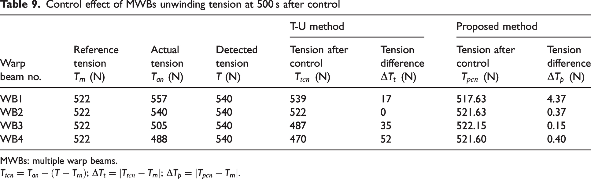
MWBs: multiple warp beams.
Other parameter changes after MWBs unwinding tension control
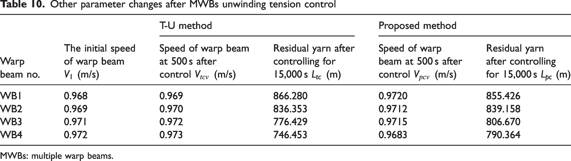
MWBs: multiple warp beams.
CV value of different parameters after MWBs unwinding tension control
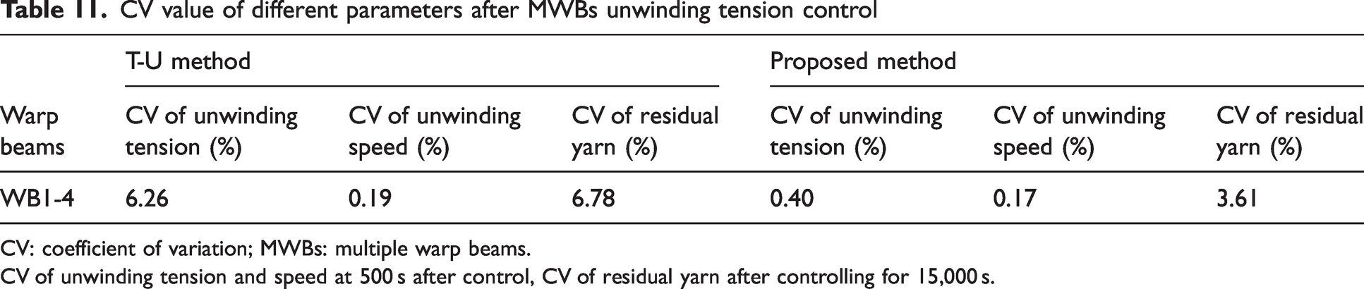
CV: coefficient of variation; MWBs: multiple warp beams.
CV of unwinding tension and speed at 500 s after control, CV of residual yarn after controlling for 15,000 s.
Experiment and result analysis
The practical application of the unwinding turns measuring device is shown in Figure 18. The measuring device is easier to install than the tension sensor and can simultaneously monitor MWBs in real time. More importantly, it is low cost and can be prone to be adopted in factories. The measurement results of the number of unwinding turns for MWBs of the traditional tension control method after a certain time are shown in Table 12. There are differences in the number of unwinding turns for each warp beam. As time goes by, this difference will gradually increase. It indicates that the unwinding tension and speed of each warp beam are inconsistent, which will eventually increase the CV of the residual yarn amount of each warp beam.
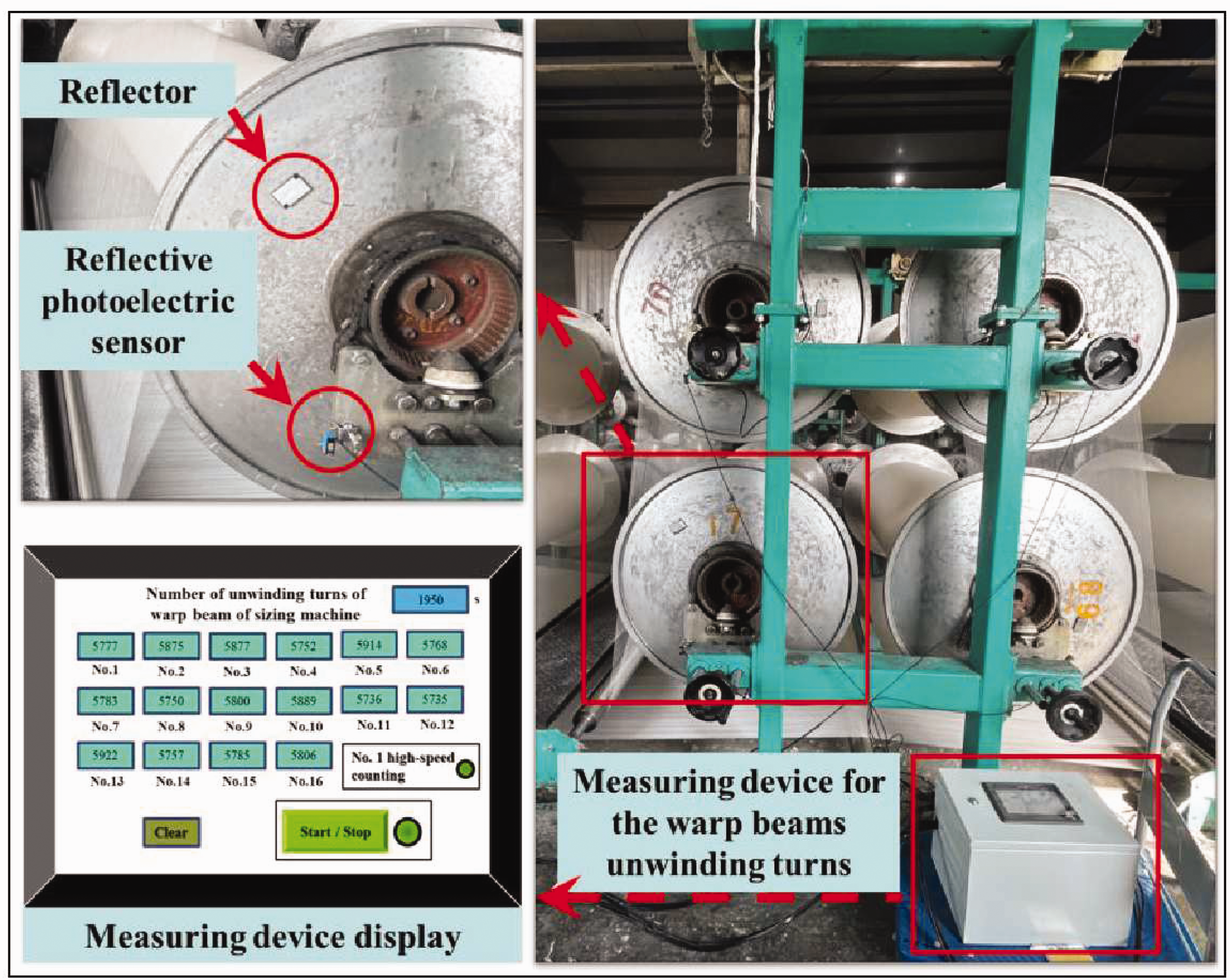
Practical application of the unwinding turns measuring device.
The measurement results of the number of unwinding turns for MWBs of the traditional tension control method after a certain time
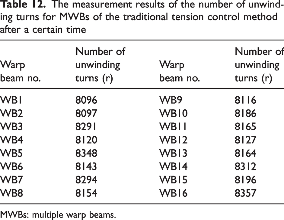
MWBs: multiple warp beams.
Detection devices for unwinding tension, unwinding speed, unwinding radius and unwinding turns were built respectively. The unwinding tension control effect of the T-U method was measured in the actual factory, as illustrated in Figure 19. The unwinding process of four different types of warp beams from full beam to empty beam was tested, including 8S air-jet vortex spinning cotton yarn (AJVA-C-8), 9S ring spinning cotton yarn (RS-C-9), 10S slub cotton yarn (S-C-10), and 75D/25D elastic ply polyester yarn (EP-P-7525).
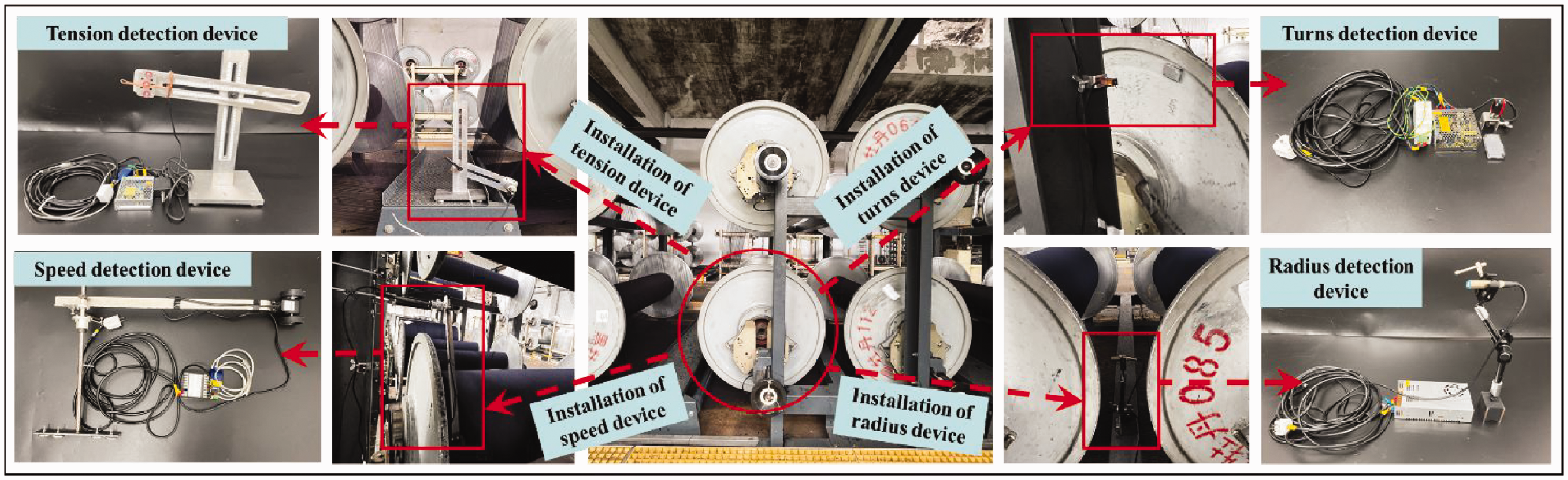
Detection device and its installation.
The measurement results of the single yarn unwinding tension for each warp beam at nearly constant speed are depicted in Figure 20. The unwinding tension still has large tension fluctuations after being controlled by the T-U method. When the unwinding radius of the warp beam is small, the unwinding speed changes rapidly and the tension fluctuation increases significantly. This phenomenon is mainly due to the small moment of inertia of the small warp beam, and the warp beam is more susceptible to changes in speed. Consequently, it is difficult for the control system to adjust quickly to offset the tension changes caused by speed changes, ultimately causing greater tension fluctuations. Significantly, the variations in the unwinding radius and unwinding speed are the main influencing factors of unwinding tension. It is consistent with the warp beam dynamics model (equation (18)) within this paper.
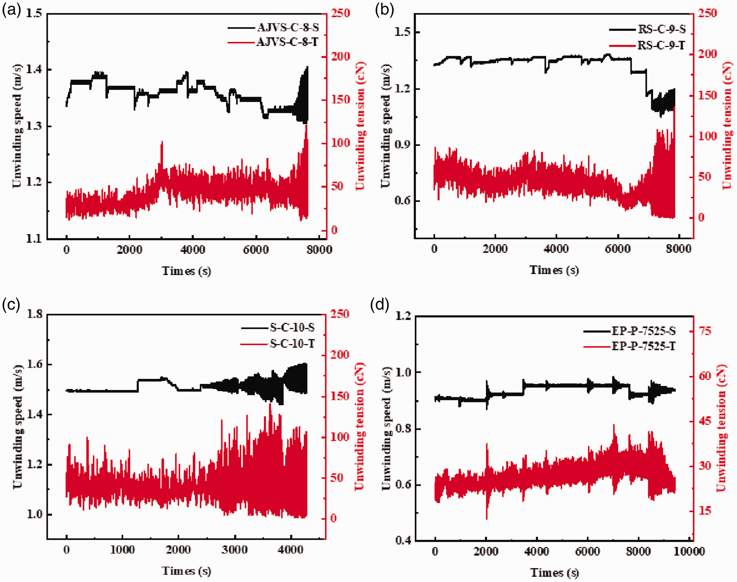
Measurement results of the single yarn unwinding tension for each warp beam at nearly constant speed.
The CV values of the single yarn unwinding tension and unwinding speed for each warp beam after being controlled are presented in Table 13. The unwinding tension CV value of EP-P-7525 after control is the smallest. There are also certain differences between different spinning methods of the same cotton yarn. It shows that yarn characteristics (elastic modulus, etc.) also have a great influence on tension. Furthermore, the tension and elongation changes of the 20S compact spinning cotton yarn (CS-C-20) and the 40S ring spinning cotton yarn (RS-C-40) during stretching were measured, as shown in Figure 21. The greater the yarn tension, the greater the yarn elongation. Each elongation is generated by a corresponding speed difference, which further explains that the greater the speed difference, the greater the tension. This phenomenon aligns with the yarn dynamics model (equation (8)) established in the paper. The tension in the unwinding area ensures that the yarn is straightened and unwound stably. The elongation of the yarn is small. During the stretching process, the fibers between the yarns will slip or transfer internally or externally. Therefore, its mass does not change before and after stretching.
CV values of the single yarn unwinding tension and unwinding speed for each warp beam after being controlled by the T-U method
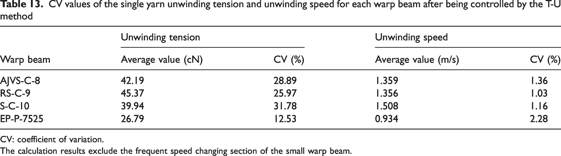
CV: coefficient of variation.
The calculation results exclude the frequent speed changing section of the small warp beam.
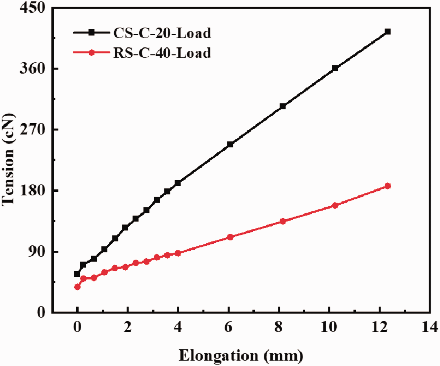
Changes of the yarn tension and elongation.
Based on the measurement results of the unwinding radius and the number of unwinding turns, the thickness of each yarn layer on the warp beam can be calculated, as illustrated in Figure 22. The thicker the yarn count, the greater the thickness of each yarn layer. In addition, the thickness of each yarn layer on all warp beams fluctuates around a constant value. The winding density of the warp beam is the mass of yarn per unit volume. Therefore, as the unwinding radius decreases, the winding density will show a slightly increasing trend, which is consistent with the change law of winding density mentioned in the paper.
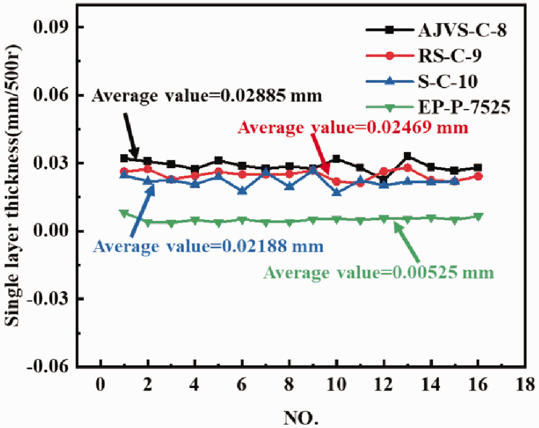
Thickness of each yarn layer during the entire unwinding process.
Therefore, after being controlled by the T-U method, the unwinding tension of the warp beam continues to exhibit fluctuations. It is necessary to adopt our proposed method to improve further the stability and uniformity of the warp beam unwinding tension.
Conclusions
In summary, the SWB and MWBs unwinding tension closed-loop control is achieved by taking the unwinding length as the control objective and using the self-developed turns measuring device for real-time monitoring. Through dynamic analysis of the warp yarn and warp beam, we establish the mathematical model between different factors and unwinding tension, further clarifying the tension fluctuation mechanism. Besides this, the simulation experiments are conducted for analyzing the control effects of the proposed methods by comparing them with the traditional methods. The main conclusions are summarized as follows:
During the warp beam unwinding process, the coupling effect among factors such as unwinding radius, unwinding speed, winding density and moment of inertia leads to changes and fluctuations in the unwinding tension. The establishment of a dynamic model between them is the basis of theoretical analysis. The proposed SWB unwinding tension control method can achieve constant tension under different reference tensions and disturbances, which is superior to the T-OL method and has the similar control effect to the T-CL method. When the speed step interference occurs, the tension can be recovered quickly within 0.5s. In addition, the proposed MWBs unwinding tension control method is also better than the T-U method. There is basically no difference in unwinding tension for each warp beam after control by the proposed method, due to our measuring device being easily installed on the SWB for control.
Through the unremitting efforts of the team, we have completed the simulation work in general. The unwinding tension, speed, radius, and turns measuring device have been successfully constructed and implemented in practical applications. The mathematical model proposed in this paper has been partially verified through measurements. In the future, we will conduct more experiments to apply the proposed method on the sizing machine.
Footnotes
Declaration of conflicting interests
The author(s) declared no potential conflicts of interest with respect to the research, authorship, and/or publication of this article.
Funding
The author(s) disclosed receipt of the following financial support for the research, authorship, and/or publication of this article: This work was supported by the National Natural Science Foundation of China (grant no. 52003105), the Natural Science Foundation of Jiangsu Province (grant no. BK20221061), and the Fundamental Research Funds for the Central Universities (grant no. JUSRP121030).