



Abstract
The synthetic filament winder drives the filament through the traverse mechanism with rotary wings so that it can complete the transverse reciprocating motion when it is continuously wound and achieve the spiral distribution on the cylindrical package. When the existing traverse mechanism leads the filament, the filament is easy to oscillate and breaks away from the control of the rotary blade during the reversing process at both ends of the package, which directly affects its forming on the package. In this study, firstly, the filament leading process is analyzed from the filament leading principle of the traverse mechanism with rotary wings and the key points of the profile are identified. Secondly, we applied parameter constraints of key points and developed a blade profile that can not only meet the demand of filament reversing but also improve the above abnormal phenomena by curve-fitting, so that the blade can continuously and stably lead and control the filament during the reversing process. Finally, through the actual winding experiment, we contrasted the state of the filament leading process of the original blades with the improved blades, and verified the improvement effect. This study provides a design basis and optimization reference for realizing a smooth and stable relay between the filament and blades.
The winder plays a crucial role in the production of synthetic filament. Among its components, the traverse mechanism with rotary wings is a key element. It allows the filament to achieve reciprocating motion and guides it into the winding structure. The reciprocating motion cooperates with the rotational motion of the spindle to wind the filament onto the cylindrical package. In other words, the quality of the filament leading characteristics of the mechanism will directly affect the quality of package formed, and it will also affect the quality of operation of subsequent processes.1–3 The leading plate and the blade are two critical parts of this mechanism, and their profiles directly influence the winding process.
For the profile design of the traverse mechanism with rotary wings, many scholars have carried out relevant research: Zheng and Xie 4 gave the design equation of the approximate profile curve of the leading plate by analyzing the PS-4 winding machine. Yang et al. 5 designed the profile of the leading plate as a circular arc by analyzing the TW-710 winding head, which satisfies the movement law of the lead filament and facilitates processing. Zhang et al. 6 determined the connection of the structural parameters through the geometric relationship and obtained the regularity of the reciprocating velocity of the filament by analyzing the velocity composition. Finally, by adjusting the structural parameters, the reciprocating velocity of the filament changed more uniformly. Ma et al. 7 conducted a simulation analysis of the dynamic behavior of the filament winding system during the reversing process, and found that the filament does not contact the blade at the moment of reversal. Koranne et al. 8 developed three kinds of improved blades for the three major defects of the existing blade leading filament mechanism from the structure. The theoretical research on the traverse mechanism with rotary wings is comprehensive and provides a rich theoretical basis for our research, but at the same time, it is equally important to observe and analyze it from the actual winding machine. We further studied the filament leading characteristics of the traverse mechanism with rotary wings from the winding in practice.
Upon further study of the winding, a notable issue emerged: the filament was clearly slipping out of the control of the blades during the reversing process, and this had a direct and adverse impact on the quality of the final package. So this article is aimed at the abnormal phenomenon of pre-oriented yarn (POY) during the winding process, such that the filament easily oscillates and breaks away from the control of the rotary blade on the winder. Firstly, the filament leading process is analyzed from the filament leading principle of the traverse mechanism with rotary wings and finds out the key points of the profile. Next, we carried out parameter constraints of key points, and developed a blade profile that can not only meet the demand of filament reversing but also improve the above abnormal phenomena by curve-fitting. Finally, through winding experiments, we contrasted the state of the filament leading process of the original blade with the improved blade, and the effect of the improved design was verified.
Basic theories
Taking the package forming of POY, which accounts for the largest proportion of output among synthetic filaments, 9 as an example introducing the distribution of the filament on the package: the middle section is wound with a helical line, and the reversing section at both ends is turned back in a specific curve.10–12 The physical picture of the POY package and the distribution of filament are shown in Figure 1.

Pre-oriented yarn (POY) package physical diagram and the distribution of filament.
The lateral distribution of the POY in the package depends on the movement of the traverse mechanism with rotary wings, and it comprises two primary components: a leading plate and two rotary wings. The principle of the filament leading is through one group of rotary wings to realize the transverse reciprocating motion of the filament on the leading plate, and hand over the filament at both ends of the package.13,14 Figure 2 illustrates a traverse mechanism with two-axis, three-blade rotary wings, where each wing incorporates a blade affixed to its upper part. Notably, the two rotary wings are eccentrically mounted and turn in opposite directions, while the leading plate remains stationary.
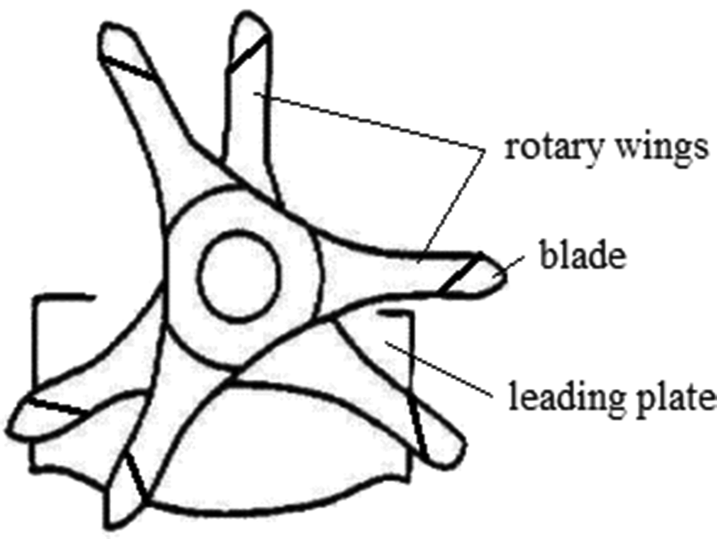
The traverse mechanism with rotary wings.
In Figure 2, the lengths of the three rotary wings are equal, and the angle between each pair is 120°. To describe how the filament is led, the rotary wing is simplified into a line according to its maximum radius, and the positional relationship between the two rotary wings and the leading plate is shown in Figure 3. In Figure 3, O1 is the center of the counterclockwise rotating wing, O2 is the center of the clockwise rotating wing, and the distance O1O2 is the eccentricity of the center of the two rotary wings.

Schematic diagram of the position of the two wings and the leading plate.
In Figure 3(a), the counterclockwise rotating wing 1 and the clockwise rotating wing 2 have just completed the handover task of the filament at the left end of the leading plate. Wing 1 leads the filament counterclockwise. When it reaches the right end of the leading plate, wing 3 also arrives just in time to carry out the handover of the filament, as shown in Figure 3(b). At this time, wing 1 rotates 60°, that is to say, the handover of the filament is completed by a pair of rotating wings with opposite rotation directions. Every time the wing rotates 60°, the filament will be handed over once.
During the filament leading process, the filament is in direct contact with the leading plate and the blade, and the blade moves the filament to reciprocate along the leading plate. Therefore, the design of the two profiles will directly determine the law and characteristics of the filament’s reciprocating motion. In this article, the profile of the leading plate and the blade in contact with the filament is called the leading profile.
The leading profile is divided into leading plate profile and blade profile. According to the movement process of the filament along the leading plate, the leading plate profile is mainly divided into the leading segment, left reversing segment, and right reversing segment, and the leading segment mainly leads the filament to complete the traverse movement. The left and right reversing segments mainly complete the reversing of the filament on the blades and the handover to counter-rotating blades.
The blade profile is mainly divided into the leading segment, reversing segment, and relay segment. The leading segment cooperates with the leading plate to complete the traverse movement of the filament. The main task of the reversing segment is to complete the reversing of the filament, which is the part where the filament contacts the blade before turning back. The relay segment primarily serves to lead the filament to reverse its direction and facilitate its handover by the counter-rotating blades. This is where the filament contacts the blade after being reversed. The reversing segment and relay segment of the blade cooperate with the reversing segment of the guide plate to complete their respective tasks. The specific segment naming diagram is shown in Figure 4.

Segmented naming diagram of the leading profile.
Against the above theoretical background, we conducted further research on the actual winder to observe in detail how the filament moves with the movements of the blades. Figure 5 is a schematic diagram of the winder. In the winder, the most critical part is the leading structure. What completes the leading is the traverse mechanism with rotary wings, the key components of which are the leading plate and the rotary wings. The filament is close to the fixed leading plate and reciprocates under the drive of the rotary wings. so that the filament enters the winding structure through the leading point, and then guided by the contact roller, the filament passes through the winding point and is wound on the rotating cylindrical package with a certain tension and distribution.
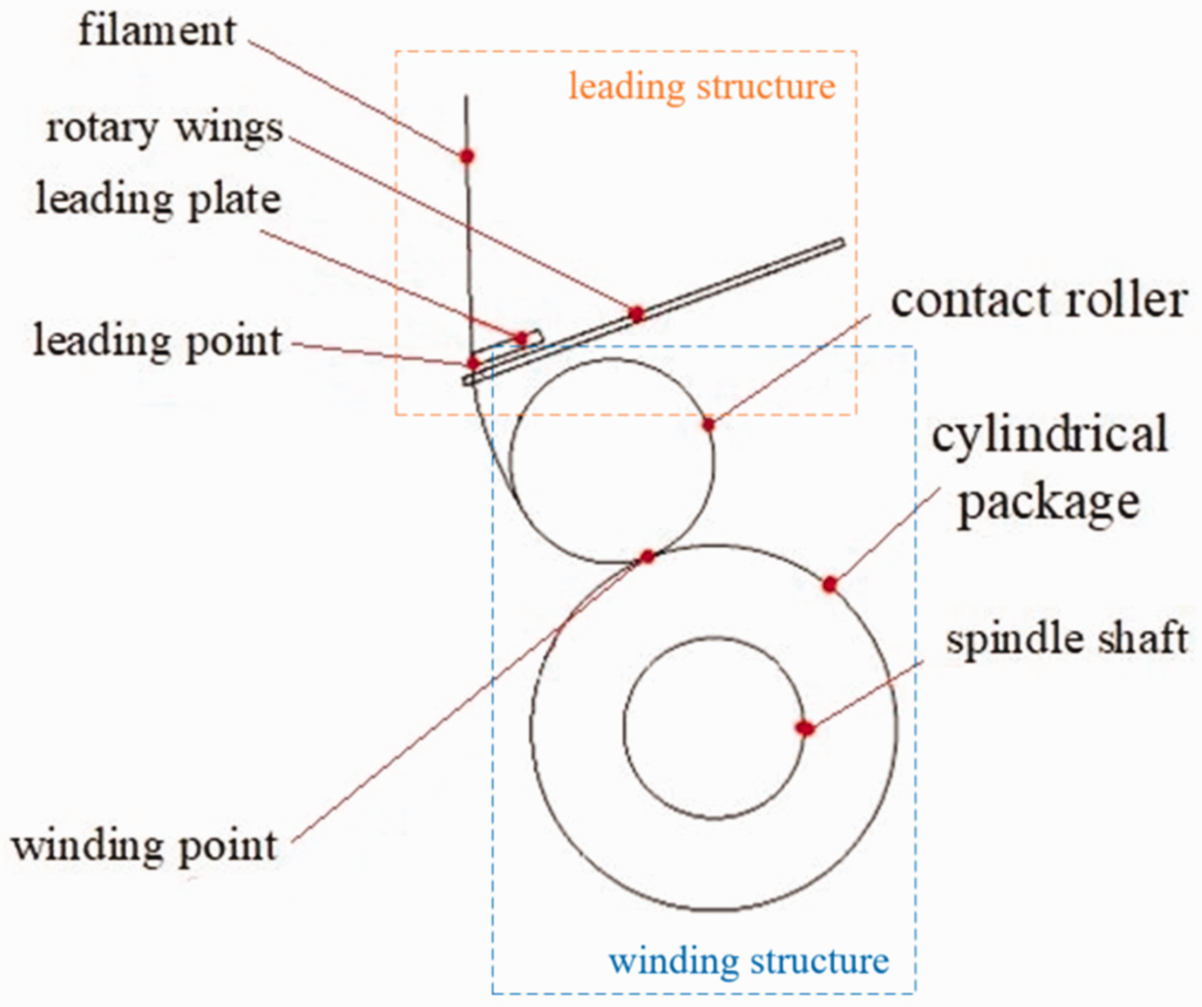
Schematic diagram of the leading filament.
Problem analysis
During the research study, we used a high-speed camera to observe the working process of a winder. During the filament’s reciprocating movement at both package ends, there are two actions: the reversing of the filament and the relay of the blade. In the overall process, we observed that the filament had significant oscillation and loss of control. Figure 6 is a series of pictures by a high-speed camera at both package ends during winding. Figure 6(a) and (b) show the reversing of the filament, and Figure 6(c)–(f) show the relay of the blade. In theory, after the filament slides along the top of blade 1, it should just contact blade 2 at the last control point of the blade to achieve a smooth relay. However, in the actual relay process, blade 2 has completed the filament reversing and ended the control of the filament while blade 2 has not yet “caught up” with the filament, and the filament slides alone on the leading plate for a certain distance before the blade 2 comes into contact with it. The entire process is far from the ideal state.

Schematic diagram of blade and filament position during reversing and relay.
The occurrence of the above situations will lead to final package problems. In milder cases, the quality of package formation may not meet the requirements. In more severe instances, it can lead to poor formation of the filament cake, which may manifest as issues like edge drop, protrusions, and sliding filament, 15 as shown in Figure 7.
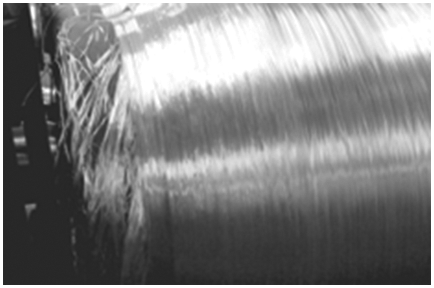
Poorly formed filament cake.
Through theoretical basis and practical observation, it can be analyzed that the root cause of the oscillation problem in the filament reversing process is that the existing blade relay segment does not control the filament after the instantaneous reversing. During the reversing segment, the velocity of the filament will gradually decrease to zero due to the need for the filament to turn back. Therefore, the filament is no longer helically wound like in the middle section of the cylindrical package, but will be wound in a kind of curved form, so the reversing segment is a kind of curved design.
According to the principle of the reversing segment, the filament has two key positions in the reversing segment of the blade. The first is the transition position between the leading segment and the reversing segment. At this time, the velocity direction does not change much, and the velocity magnitude has not started to change, so it has little influence on abnormal conditions.
The second is the junction point between the reversing segment and the relay segment. At this time, the reciprocating velocity is zero, which is also called the turning point of the filament, and its approximate position is shown in Figure 8. At the next moment, the filament will break away from the control of the reversing segment of the blade and move in the opposite direction. The movement state of the filament around the turning point changes drastically, which is a very important position and deserves further research and analysis.

Schematic diagram of the position of the turning point.
At the next moment, the filament enters the relay segment of the blade. The function of the relay segment is to lead the filament before it is connected to the counter-rotating blade after it leaves the reversing segment of the blade. Since the reversing segment is a curve, it is required that the filament must be connected by the leading segment of the counter-rotating blade. While the relay process is very short, so the filament must slide off quickly in the relay segment. However, the reciprocating velocity of filament at starting point of the relay segment, that is, the turning point, is zero, and the state of motion changes very rapidly, so the filament is prone to abnormal phenomena.
In summary, based on the leading profile analysis of the traverse mechanism with rotary wings, the relay segment of the blade has the greatest impact on the existing problems in the filament leading process. There is no doubt that the design principles for the relay segment of the existing blades are insufficient, resulting in their failure to meet expectations. So, here, we resummarize the key parameter design principles of the blade relay segment:
Minimizing the reversing time it takes to the filament is crucial for optimal package formation. During the reversing and the relay process, the vibration should be reduced or eliminated as much as possible while satisfying the fast speed. During the relay process of the filament by the blade, the time that the filament is in a free state should be minimized, ensuring continuous control through contact between the blade and leading plate. Blades with opposite rotations should ideally engage the filament precisely as it leaves the previous blade. If the filament is connected too early, the relay will fail; if it is too late, the filament may escape the blade’s control, jeopardizing precise filament reciprocation.
According to the design principles analyzed above, we were able to improve the design of the relay segment and verify the improvement effect through experiments.
Improvement method
In order to satisfy the first of the above design principles, the original relay segment was designed as a straight line to allow the filament to slide down quickly after reversing. However, this caused the filament to lose contact with the relay segment of the blade at the moment it slipped at the top of the blade, and was temporarily out of control of the blade. This is detrimental to packaging. Therefore, in this article we propose a method to improve the design of the relay segment of the blade as a curve, and the curvature is calculated according to the instantaneous acceleration direction of the filament at the moment of reversing, so that the filament does not break away from the control of the blade after passing through the turning point until the counter-rotating blade successfully relays.
But, first, it should be noted that, as shown in Figure 9, after reversing with the original blade, due to the influence of the structure of the winder the filament will generate an instantaneous acceleration of the resultant force
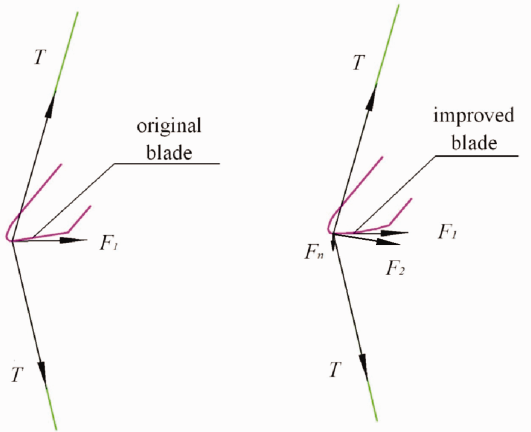
Force comparison of the filament of the two blades.
Second, although a curve is used instead of a straight line to improve the force direction, the curve is very close to a straight line, in order to ensure the rapid sliding of the filament, but curvature constraints are given at some key points so, for the convenience of research, the curve part is not drawn in the coordinate system.
Based on the above two points, for the profile design we decided to adopt the method of curve fitting. Curve fitting is based on some key points to be passed, with several constraint points to constrain the curve, and curve fitting to obtain a curve that meets the requirements.
Step 1: The selection of key points
Key point 1 is the junction point
Step 2: Mathematical parameter constraints
The parameters that need to be constrained are the slope at

Schematic diagram of
Since the time for the filament to slide down in the relay segment is extremely short, the rotation of the blade during this period can be ignored. At this time, the blade has a certain positional relationship with the leading plate. When various parameters and equations of the leading plate are known, various parameters of the blade can be deduced from the known parameters of the leading plate. Take the center

The position diagram of the blade and the leading plate.
In Figure 11,
Therefore, the length of the relay segment

At the moment of reversing, the direction of the instantaneous acceleration at
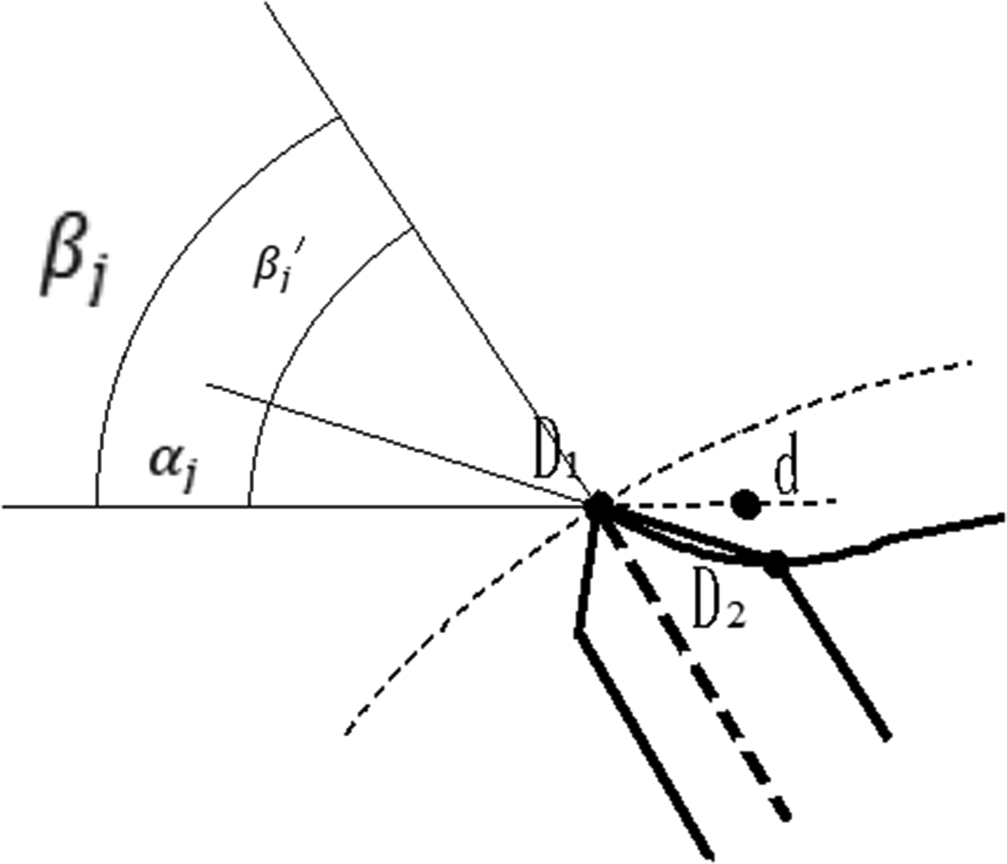
The angle diagram.
Next, we introduce a parameter: the height of the relay segment


Then the relay segment height

Therefore, the inclination angle of the original relay segment

And

In equation (5),
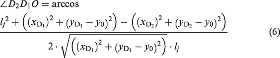
The relevant parameters are all known data, then can be obtained, so

The known parameters are shown in Table 1, and are obtained by measuring the key parameters of the existing leading plate and performing appropriate fitting.
The known parameters

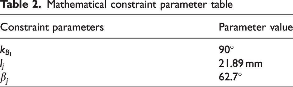
To sum up, after bringing in the known data, the various mathematical constraint parameters are shown in Table 2.
Mathematical constraint parameter table
Step 3: Curve fitting
After carefully considering constraints and smooth continuity, it was decided to use the Bezier curve for fitting. The Bezier curve is a parametric polynomial based on the idea of approximation. Its principle is to fit the curve through the positions of some control points, and the obtained curve and the polygon connected by the control points are tangents at the start point and end points of the control point. 16
If there are 

Common Bezier curves include quadratic Bezier curves and cubic Bezier curves. They require three and four control points respectively. The curves are shown in Figure 13.18,19
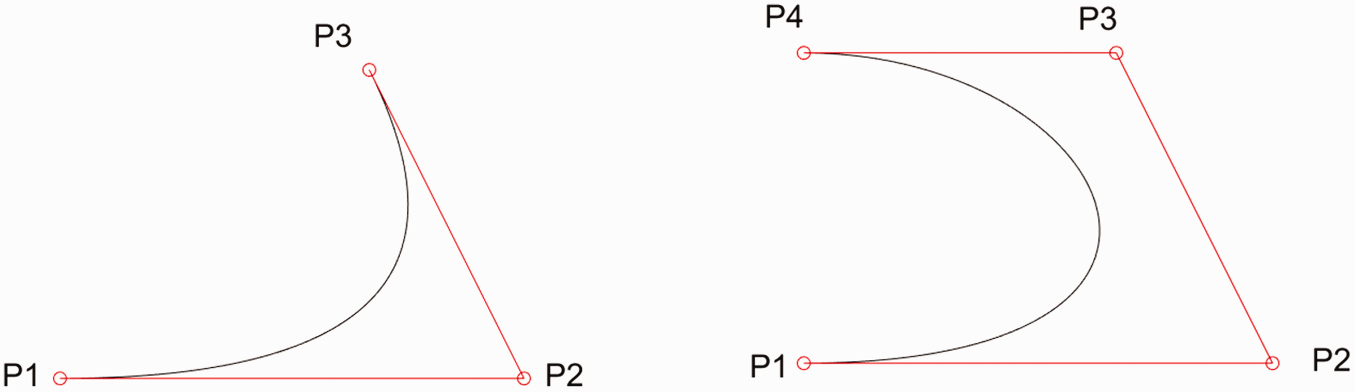
Quadratic Bezier curve and cubic Bezier curve.
The analysis above underscores that the critical factor in selecting the appropriate Bezier curve is determining the number of control points for the curve. These control points encompass not only the pivotal points through which the curve passes but also the constraint points that govern the parameters.
The selection rules correspond to the blade points as follows:
The starting point The ending point Introduce Introduce
From the above analysis, it can be seen that the control points

Schematic diagram of the improved profile of the relay segment of the blade by cubic Bezier curve fitting.
Comparative experiment
To solve the problem of oscillation and breaks away from the control at the filament leading process, we improved the profile of the relay segment of the blade after conducting the above theoretical research. Next, in order to verify the improved effect, our findings were compared with the original blade. The method was to fit two kinds of profiles in MATLAB at the same time to observe the difference between the curves. Subsequently, both types of blades underwent processing under identical conditions. An actual winding experiment was conducted using both sets of blades, and the condition of the blades was observed by a high-speed camera.
According to the known control point parameters of the relay segment profile of the original blade, the control point parameters of the improved blade can be obtained, as shown in Table 3.
Comparison table of control points of two blade relay segment profiles
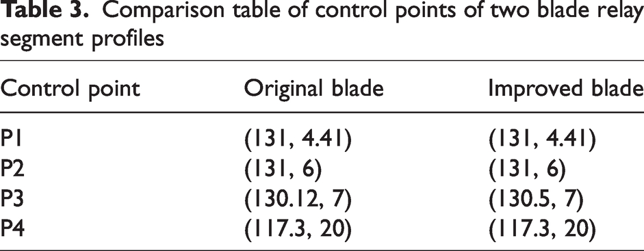
Inputting the parameters into MATLAB and performing curve fitting, respectively, we obtained the comparison chart shown in Figure 15.

Comparison of the profile of the relay segment of two kinds of the blade.
It can be seen that the improved curve alters little on the whole and, since the profiles are very close to straight lines, this can ensure the rapid decline of the filament. However, due to the increase in the inclination angle, the improved curve is obviously more “convex” than the original blade. This increased curvature enhances the likelihood of contact between the filament and the blade after traversing the turning point. Next, the two blades were processed with the same materials and with the same processing method for subsequent experimental verification. As Figure 16 shows, the shape of the blades was consistent with the fitted results. The pink one is the original blade, and the white one is the improved blade. The picture on the right is the overlapping comparison of the two blades.

The blade contrast diagram.
As the experiment required the observation of the leading plate and blade, utilizing the actual winder was inconvenient. Consequently, the winding process was simulated by unwinding the package. The primary aim of this experiment was to compare the performance of the improved blade with that of the original blade in addressing the following two filament-leading issues:
Whether the vibration of the filament at the moment of reversing had been improved. During the relay process of the two blades, whether the free advance segment of the filament is reduced, and whether the relay process was smoother and more continuous.
Figure 17 is a schematic diagram of the experimental scheme.
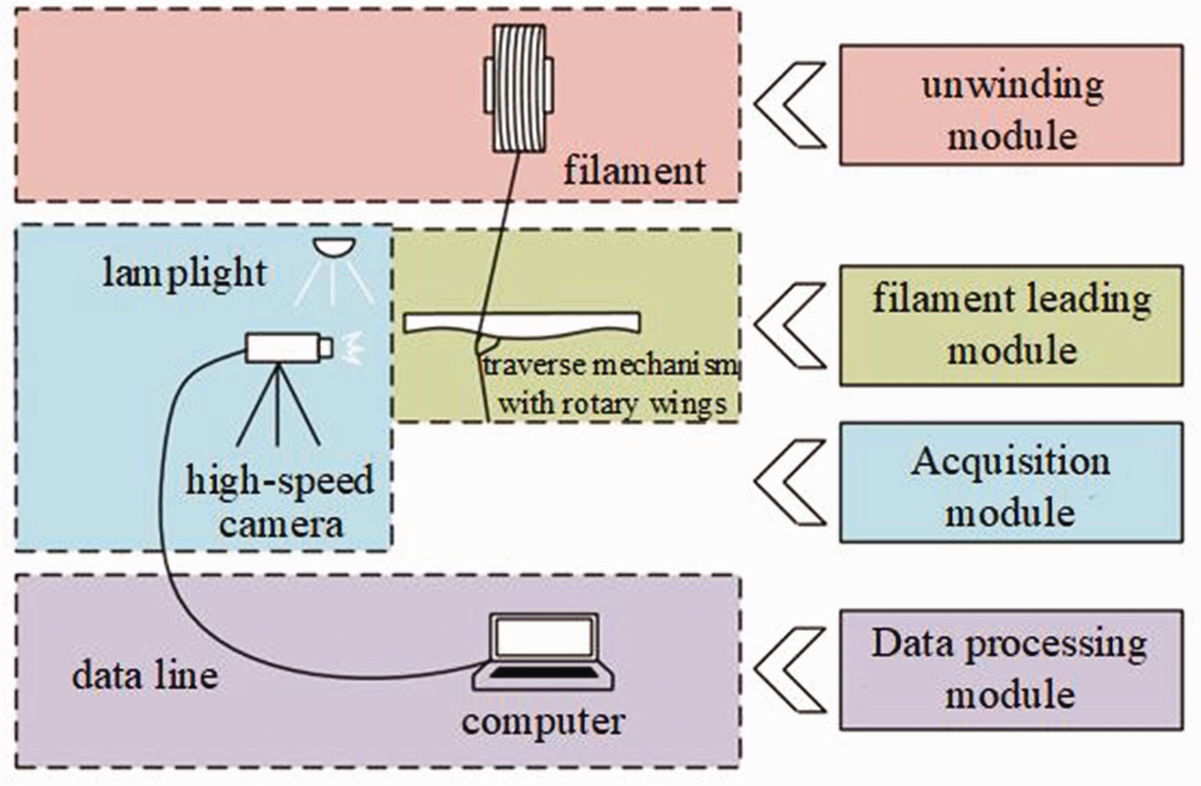
Experimental scheme diagram.
The unwinding and filament leading module primarily consist of components such as the POY package, unwinding device, filament-leading device, the traverse mechanism with rotary wings, cylindrical package, and leading filament hook, among others. To facilitate observation, the original blade was installed on the cylindrical package 1, and the improved blade was installed on the cylindrical package 2. The filament led by the leading filament device was located in the middle of the position 1 and the position 2, so that the tension of the filament was roughly equal during the winding process of the two positions. The schematic diagram of the experimental device is shown in Figure 18, and the experimental scene is shown in Figure 19.
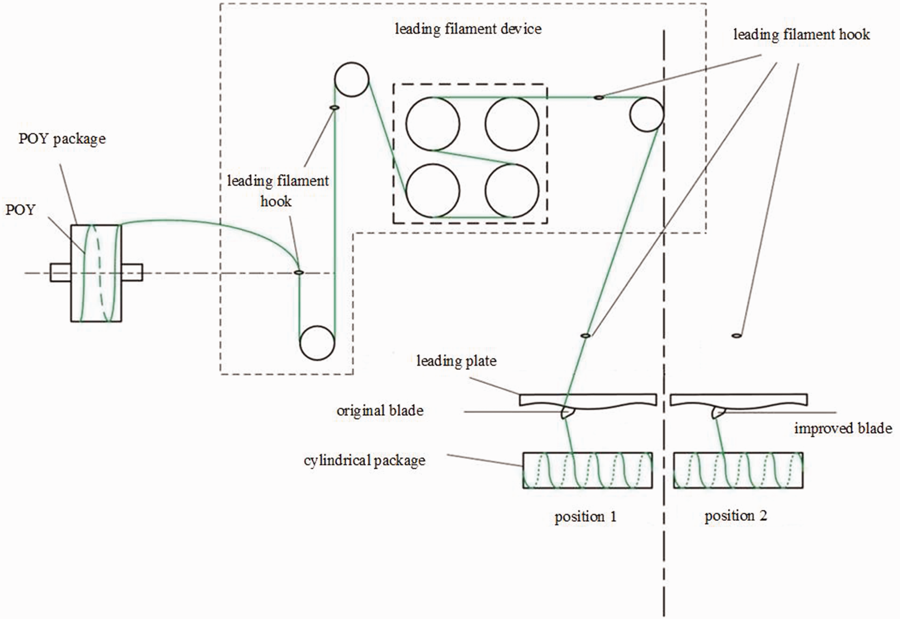
Schematic diagram of the experimental device. POY: pre-oriented yarn.

Experimental scene.
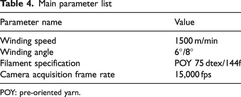
The experimental parameters were selected according to the typical POY winding process parameters, and the winding speed of the package was usually less than 3000 m/min. Considering the experimental requirements, we took the speed of 1500 m/min, which was beneficial to observe the motion of the filament. The commonly used winding angle ranges from 6–8°. In order to better verify the improvement effect, we took 6° and 8° to enable experimental comparison between the two groups of blades. 20
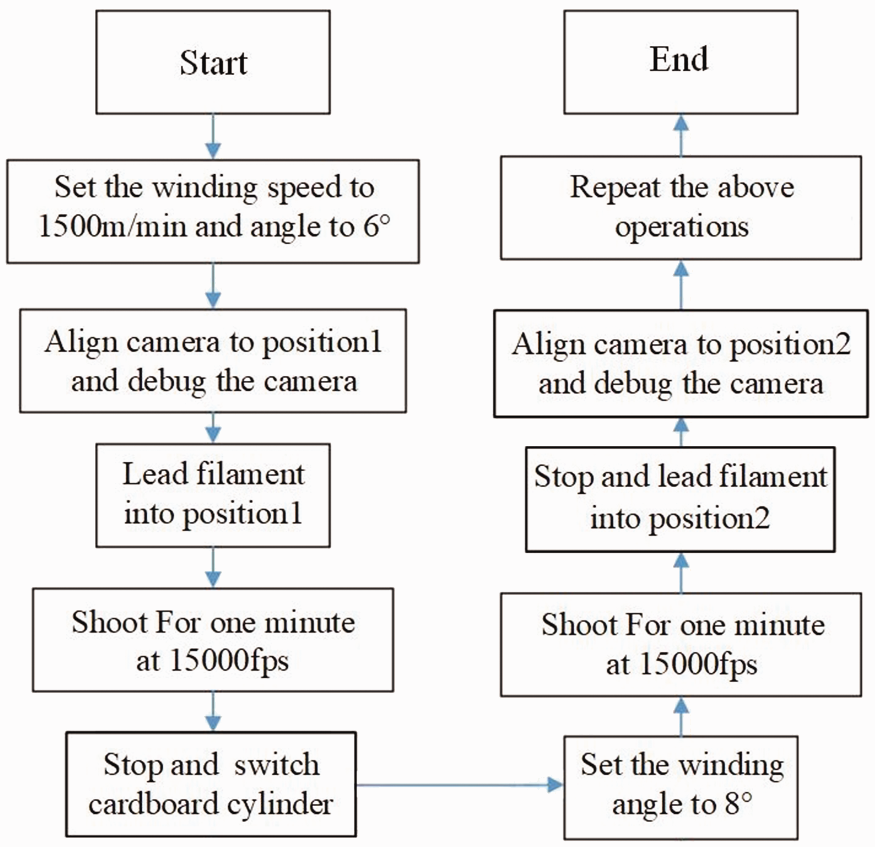
The experimental process was as follows: set the main parameters of the test plan (winding speed 1500 m/min, winding angle 6°), install and debug the high-speed camera, open the experimental device, introduce the filament to the position 1, start up the winding of the filament. start timing from the filament winding to the package, and use the high-speed camera at 15,000 fps to take pictures of the filament reversing process at the left end of the package under the lead of the original blade in one minute; then stop the experimental device and switch the cardboard cylinder on the package. Then set the winding angle to 8° and repeat the above operation to eliminate accidental;
After the reversing process of the original blade was collected, the filament was introduced into position 2, and all operations of the original blade were repeated. The parameters involved in the whole experiment are shown in Table 4, and the flow chart is shown in Figure 20.
Main parameter list
POY: pre-oriented yarn.
Experimental flow chart.
Results and discussion
Step 1: Processing of pictures
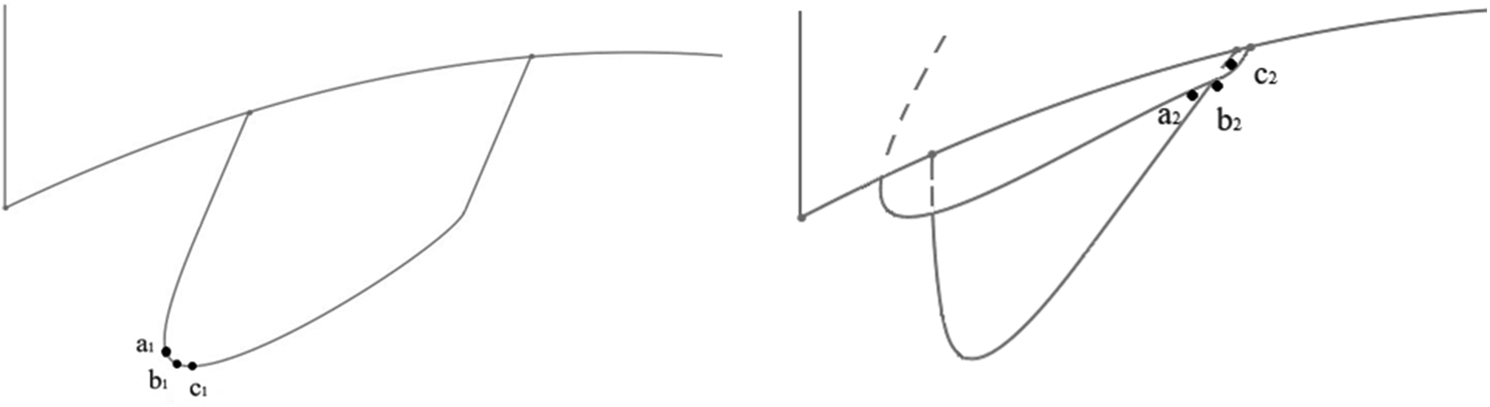
What we paid attention to was the state change of the filament when the blade reverses and relays, so we defined the position of the filament during the blade actions, as shown in Figure 21, “a1” is the position of the previous moment of reversing, “b1” is the position where the reversing is in progress, “c1” is the position of the next moment of reversing, “a2” is the position of the previous moment of relay, and “b2” is the position where the relay is in progress, and “c2” is the position of the next moment of relay.
Approximate position diagram of filament reversing and relay in the extracted pictures.
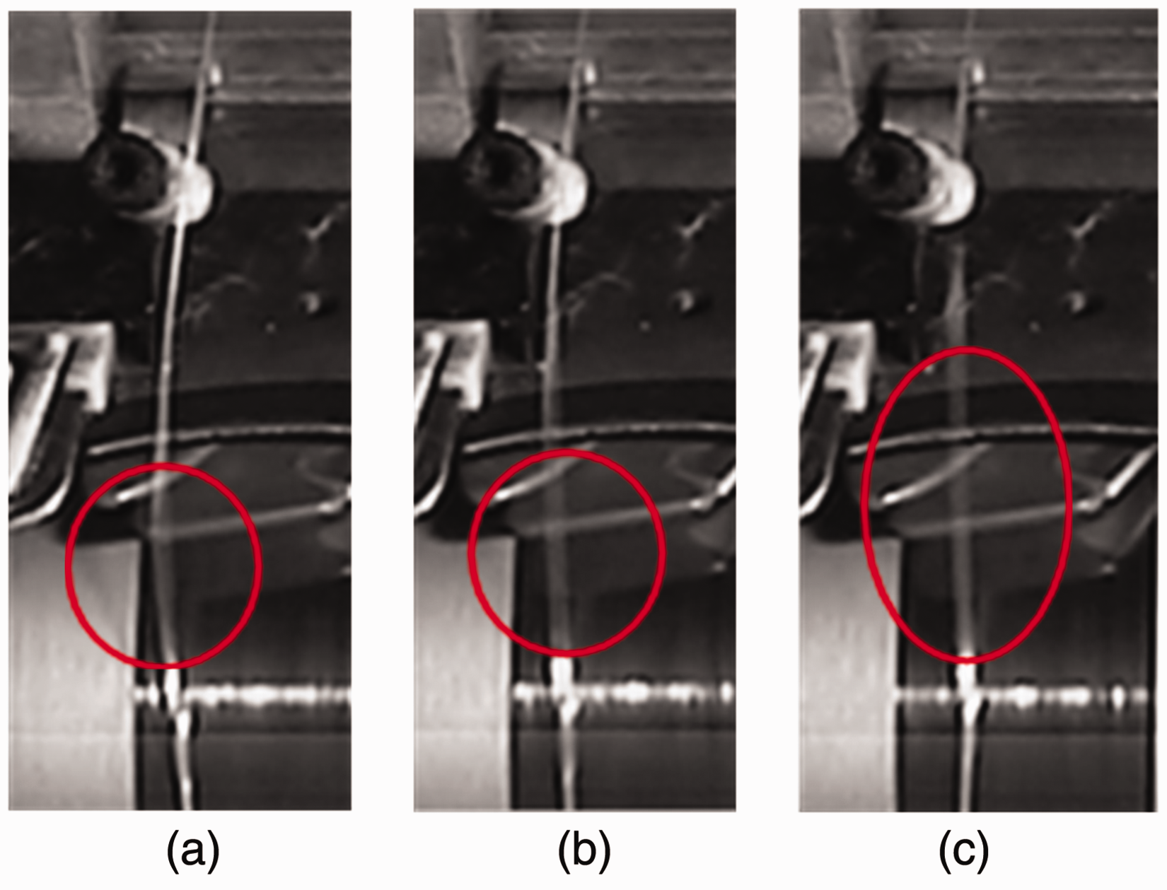
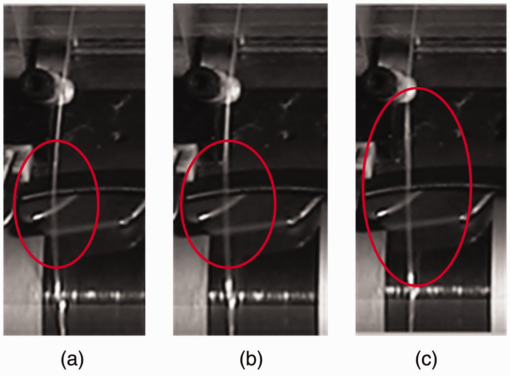
Next, we saved the pictures taken by the camera frame by frame, then extracted the actions process of reversing and relay, and named the pictures of the processes as (a), (b), and (c) chronologically. Thus, the picture named (a) corresponds to position “a1” or “a2,” and so on. Next, we observed the filament’s motion process and compared the different states of it on the two blades (Figures 22–29).
The process of reversing of the original blade with a winding angle of 6°.

The process of reversing of the improved blade with a winding angle of 6°.
The process of reversing of the original blade with a winding angle of 8°.

The process of reversing of the improved blade with a winding angle of 8°.

The relay process of the original blade with a winding angle of 6°.
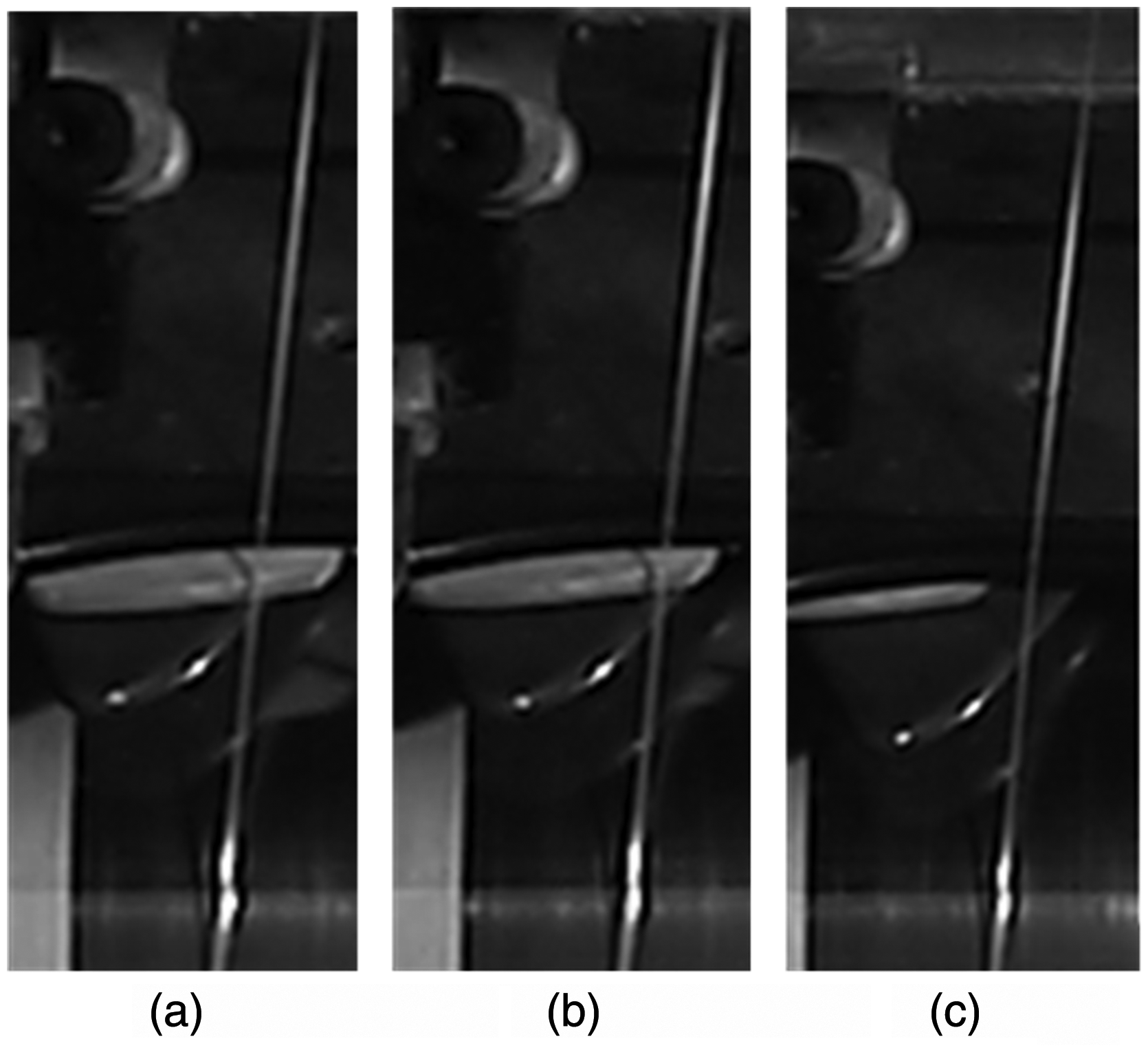
The relay process of the improved blade with a winding angle of 6°.
The relay process of the original blade with a winding angle of 8°.

The relay process of the improved blade with a winding angle of 8.
Next, we used image processing technology to process and analyze the motion state of the filament to convert it into specific images and numbers, and further verify the experimental results.
For a large number of collected images, we first used an algorithm based on feature extraction to preprocess the images, and accurately and efficiently screened out the characteristics of the filament. Next, we applied an algorithm based on image subtraction. Under the premise of retaining the characteristics to the greatest extent, the background information was effectively removed and the features of the filament were highlighted. Then, we calculated coordinate points at designated positions of the filament based on the principle of vector cross-product, and the coordinates in the process of transverse movement were extracted. Finally, we imported the coordinates into the analysis software and plotted the desired curve. The key image obtained during the image processing process is shown in Figure 30.

Key diagrams of image processing process.
After further processing by analysis software, a comparison chart of the reciprocating velocity of the filament at the moment of reversing under the control of the two blades was obtained, as shown in Figure 31.

Reciprocating velocity comparison chart.
Step 2: Discussion of results
By observing the state of the filament at the critical position, the following results can be obtained.:
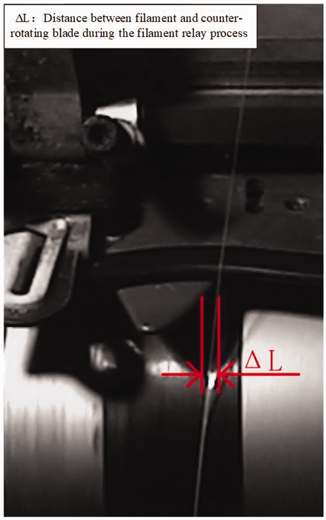
By comparing Figures 22 and 23, compared with Figures 24 and 25, it can be seen that the clarity of the filament had changed, this is because in Figures 22 and 24 the filament was moved past the reversal point by the original blade, the obvious oscillation occurred, as shown in the red circle range. In contrast, at the same position, in Figures 23 and 25 the degree of oscillation is significantly reduced under the movement of the improved blades, so in the image, the clarity of the filament changes. This shows that no matter whether the winding angle is 6° or 8°, good improvement effects can be achieved: the vibration amplitude of the filament is smaller and the state is more stable when the improved blade is reversed, which preliminarily verifies the effectiveness of the improvement. As shown in Figures 26 and 28, during the relay process, after the filament slips from the relay segment of the original blade, the counter-rotating blade still has a certain distance from it ( By analyzing Figure 31, compared with the original blade, firstly, the reciprocating velocity change of the improved blade is obviously smaller, and the improvement of the blade reduces the reciprocating velocity change by nearly 40%. Secondly, the velocity of the original blade also fluctuates greatly when entering and leaving the reversing zone, and the velocity change of the improved blade when entering and leaving the reversing zone is smaller, which has less impact on package quality.
In summary, we have verified the effectiveness of blade improvement as discussed above, and the overall effect of the experiment is in line with the expected goal.
Conclusion
This study was based on the phenomenon that the filament will produce oscillation and break away from the blade during the reversing process of the filament winder. It was based on the basic design method of filament leading profile, analyzing the profile effects of the traverse mechanism with rotary wings. It was proposed to improve the design of the profile of the relay segment of the blade as a curve to improve the abnormal phenomenon, and the curve of the relay segment was fitted by defining parameter points. Next, through the method of engineering experiment comparison, the movement of filament reversing under the two blades was compared, and it was fully verified that the improved design can ensure the rapid decline of the filament, while effectively reducing the velocity jump of the filament during the reversing process, reducing the oscillation of the filament, making the relay of the blades more stable, and improving the stability of the overall motion of the filament.
However, by combining the overall movement of the filament with the actual structure of the winder, it was found that the final winding effect on the package is not only affected by the traverse mechanism with rotary wings but also by the rotational movement of the contact roller. To obtain the optimal winding effect, we need to start from another aspect and conduct further detailed research.
Footnotes
Declaration of conflicting interests
The author(s) declared no potential conflicts of interest with respect to the research, authorship, and/or publication of this article.
Funding
The author(s) disclosed receipt of the following financial support for the research, authorship, and/or publication of this article: This study was supported by the Fundamental Research Funds for the Central Universities (grant numbers 2232023G-05-1).
