



Abstract
Carbon fiber-reinforced epoxy matrix composite laminates have been widely used in the case of advanced aero-engines, due to their high specific mechanical properties and mature production technology. In order to predict accurately the transverse mechanical properties of composites, this paper developed a multiscale analysis method which consists of three scales: At the microscale, an interfacial cohesive zone model is established based on atomic potential energy to describe the interface. At the mesoscale, a unit cell model is established to represent the fiber, matrix, and interface. At the macroscale, the homogenization method, failure criteria, and damage degradation models are utilized to predict transverse mechanical properties. The results of predictions are compared with experimental tests, and it is found that the maximum errors are less than 3%. Furthermore, the predicted damage evolution path aligns with the experimental results, thus validating the accuracy of the multiscale analysis method. By employing the multiscale analysis method, the effects of interfacial strength on the macroscopic transverse mechanical properties are analyzed. The simulation results indicate that: The interfacial strength has a more pronounced influence on the transverse strength and ultimate strain compared with the transverse modulus. Reducing the interfacial strength has a greater influence on the transverse modulus, strength, and ultimate strain than increasing the interfacial strength. The interfacial cohesive zone model can reflect the nonlinearity of epoxy matrix composite materials. Overall, the multiscale analysis method proves to be effective in accurately predicting the transverse mechanical properties of composites, and provides insights into the interfacial strength’s role in these properties.
Keywords
Carbon fiber-reinforced epoxy matrix composite laminates have been widely used in the case of advanced aero-engines, due to their high specific mechanical properties and mature production technology. 1 During its service, the aero-engine case will suffer axial, circumferential, and radial loadings, which are caused by the airflow shock, pre-tightening force and centrifugal force, respectively. 2 The transverse tensile strength is much smaller than the longitudinal tensile strength, and composite failure occurs easily under transverse tensile load. Therefore, it is of great engineering significance to study the transverse mechanical properties of composite laminates.
Unidirectional fiber-reinforced composites are composed of fibers, matrices, and interfaces, and are known as hierarchical materials with three structural scales: microscale, mesoscale, and macroscale. At present, mesoscale methods are usually applied to predict the mechanical properties of composites, thereby serving as theoretical tools for engineering structural design. 3 Mesoscale methods for the mechanical properties of composites include the asymptotic expansion method,4,5 the Voronoi cell finite-element method (VCFEM),6,7 and the method of cells (MOC). 8 The two-scale asymptotic expansion method is a systematic way of improving Bernoulli’s theory by including higher-order terms without any assumption. 4 VCFEM is a two-dimensional automatic mesh generation technique for composites, in which the second phase consisting of particulates or unidirectional fibers are randomly dispersed in the matrix. 6 These two methods have high accuracy, but low efficiency. Among them, MOC is mostly used because of its high computational efficiency.9,10 MOC divides the representative unit into simple sub-cells including fiber sub-cells and matrix sub-cells, which makes it easier to solve the equilibrium equation in the sub-cells and greatly improves the computational efficiency. Aboudi first proposed MOC in 1981, 11 and then promoted to the generalized MOC in 1992. 12 By now, there is a large number of studies on the mechanical properties of fiber-reinforced composites based on MOC; these mechanical properties are fundamentally important in design phases. Li and Zhang 13 assumed that the carbon fiber was transversely isotropic and that the resin matrix was viscoelastic and used a unit cell model to study the viscoelastic stiffness of a carbon fiber-reinforced resin matrix composite. Xia and Zhang 14 applied periodic boundary conditions to a parallelepiped unit cell to predict the stiffness of fiberglass-reinforced resin matrix composites. Hackett 15 used a unit cell model in cylindrical coordinates to analyze the equivalent stiffness of carbon nanotube (CNT)-reinforced resin matrix composites. Prodromou and Lomov 16 investigated the equivalent stiffness of complex braided composites by combining a unit cell model with WiseTex. Sha and Ding 17 used a unit cell model to explore the transverse elastic modulus and Poisson’s ratio of unidirectional fiber-reinforced composites with different lay-ups. However, in these studies of mesoscale methods, the interface between the fiber and the matrix was not taken into consideration, which may result in the inaccurate mechanical property prediction. In order to solve this problem, some researchers adopted macroscopic cohesive zone models as interface models, such as the bilinear cohesive zone model 18 and the exponential cohesive zone model. 19 Wang and Zhang 20 and Han and Guan 21 studied the transverse strength and damage behavior of unidirectional fiber-reinforced composites by introducing a macroscopic cohesive zone model of the interface into a unit cell model. However, the macroscopic cohesive zone model cannot reflect the microscopic properties of the interface. The microscopic properties of the interface have a significant effect on the macroscopic mechanical properties of composites, 22 and it is necessary to investigate the microscopic properties of the interface.
As the interfacial interaction between the fiber and the matrix is actually the interaction between the fiber atoms and the matrix molecules, microscale methods based on the atomic structure were developed. To date, several researchers have proposed microscale methods to study the properties of the interface. Hadden et al. 23 used the molecular dynamics method and micromechanical modeling to investigate the effect of graphene nanoplatelet (GNP) dispersion and GNP volume fraction on the properties of the interface for a GNP/carbon fiber/epoxy hybrid composite. Johnston and Koo 24 investigated the interfacial mechanical properties using the molecular dynamics method integrated within a high-fidelity micromechanics theory. Mousavi and Arash 25 developed a coarse-grained model of cross-linked CNT-reinforced polymer matrix composites to explore the elastic mechanical behavior in the interface. Gupta and Harsha 26 proposed a microscopic finite-element modeling approach to analyze the effect of vacancy defects on the interface of the CNT-reinforced polymer matrix composites. Bedi and Tiwari 27 quantified the effect of filler composition, filler diameter, and CNT grafting on the interfacial shear strength of epoxy matrix composites using scanning electron microscopy and energy dispersive X-ray spectroscopy. Most of these studies focused only on the properties of the interface.
Huang and colleagues28 –35 and Wang and Huang 36 systematically established the true stress theory for the matrix to predict the uniaxial strengths by considering the interface debonding and slippage. Using the matrix true stress theory, an Excel table-based program for calculating all of the possible true stress components was provided. The research results show that the matrix true stress theory can accurately predict the failure and strength behaviors of composites under different load conditions. Zhou and colleagues37 –40 researched the prediction of interfacial debonding in fiber-reinforced composite laminates, and established an analytical method to estimate the load level when interfacial debonding occurs between the fibers and matrix of a composite under an arbitrary load. The research results show that for a unidirectional composite subjected to an arbitrary load, when the principal stress is positive and the von Mises stress of the matrix reaches the critical value, the applied load level when interfacial debonding occurs is determined accordingly. Liu et al. 41 considered the effect of stress concentration on a matrix, and proposed a novel micromechanics method to predict the transverse tensile strength of unidirectional composites. The research results show that based on the proposed approach, the transverse tensile strength of a unidirectional composite can be accurately predicted.
The above studies predicted the mechanical property of composites by considering the interface state, such as the interface debonding and slippage. However, there are few studies on the mechanical property prediction of composites by considering the interfacial interaction between the carbon fiber layer and resin. In this paper, a multiscale analysis method based on an interfacial cohesive zone model (ICZM) was proposed and used to analyze the effect of the microscopic properties of the interface on the macroscopic mechanical properties of composites.
The remainder of this paper can be summarized as follows. In the Experiment section, the material properties of the fiber and epoxy are given, and the preparations of the transverse tensile test and in situ tensile test are introduced. In the following section, a multiscale analysis method of the transverse mechanical property prediction for unidirectional fiber composites is developed in detail. In the next section, the application of the multiscale analysis method is introduced. In the Results section, the stress–strain curve and damage evolution were analyzed by comparing with the experimental results. In the Discussion section, the effects of the interfacial strength on the transverse properties is discussed. In the final section, some key conclusions of this work are summarized.
Experiment
Materials
Carbon fiber-reinforced resin matrix composite laminate is used for the transverse tensile specimen. T300 carbon fiber and resin were adopted as two components of the composite laminates, respectively. The material properties of the two components are listed in Table 1. The volume fraction of the carbon fiber (8 μm diameter) is 70% in the composite laminate.
Material properties for carbon fiber-reinforced resin composite components 42

Transverse tensile test
According to the ASTM D 3039-07 procedure, the transverse tensile specimen with the stacking sequence of [9016] was processed as shown in Figure 1. Figure 1(a) and (b) show its exact geometric size and experimental sample, respectively.
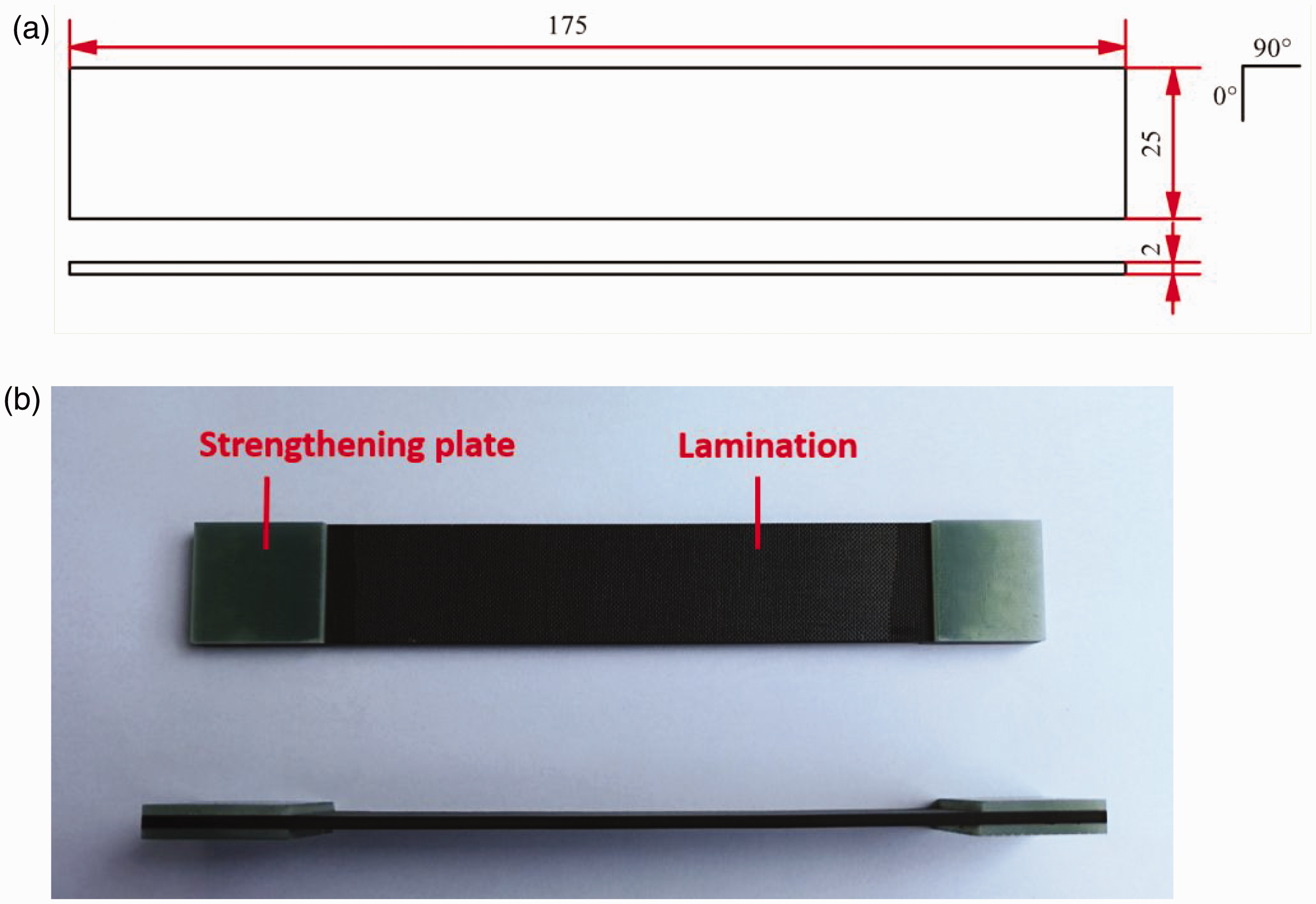
Exact geometric size of the transverse tensile specimen: (a) geometric size (unit: mm) and (b) experimental sample.
To obtain the stress–strain curve, the transverse tensile test was conducted by the UTM5105 electronic universal testing machine as shown in Figure 2(a). During the transverse tensile test, the two ends of the transverse tensile specimen were clipped by two clamps, and a constant rate of 2 mm/min was adopted for the upper clamp, as shown in Figure 2(b). Three transverse tensile specimens (T1, T2, and T3) were tested.

Transverse tensile testing equipment: (a) UTM5105 electronic universal testing machine and (b) clamping and control system.
In situ tensile test
The in situ tensile specimen was cut from the transverse tensile specimen, and its exact geometric size and practicality picture are shown in Figure 3.
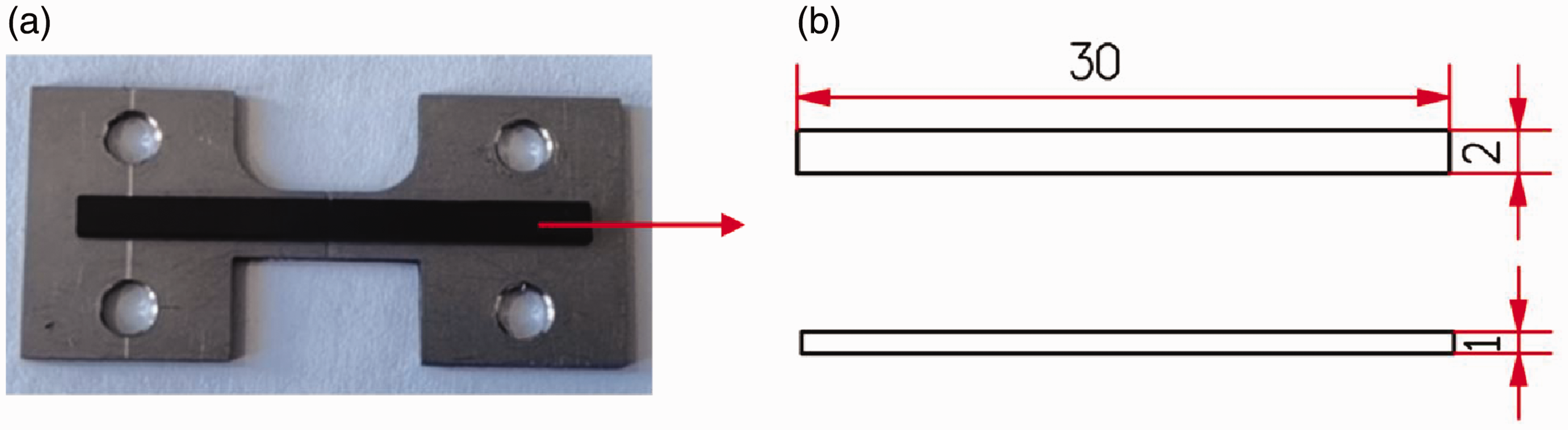
Exact geometric size of the in situ tensile specimen: (a) practicality picture and (b) geometric size (unit: mm).
To investigate the damage evolution of unidirectional laminates under transverse loading, the in situ tensile test was conducted by an in situ stretching table integrated with a Hitachi 8220 field emission scanning electron microscope (FESEM), as shown in Figure 4(a). The in situ stretching table was placed in the scan room of FESEM, as shown in Figure 4(b). During the in situ tensile test, a constant rate of 0.1 mm/min was adopted. The in situ tensile specimen was fixed on the fixture by adhesive, as shown in Figure 4(c).
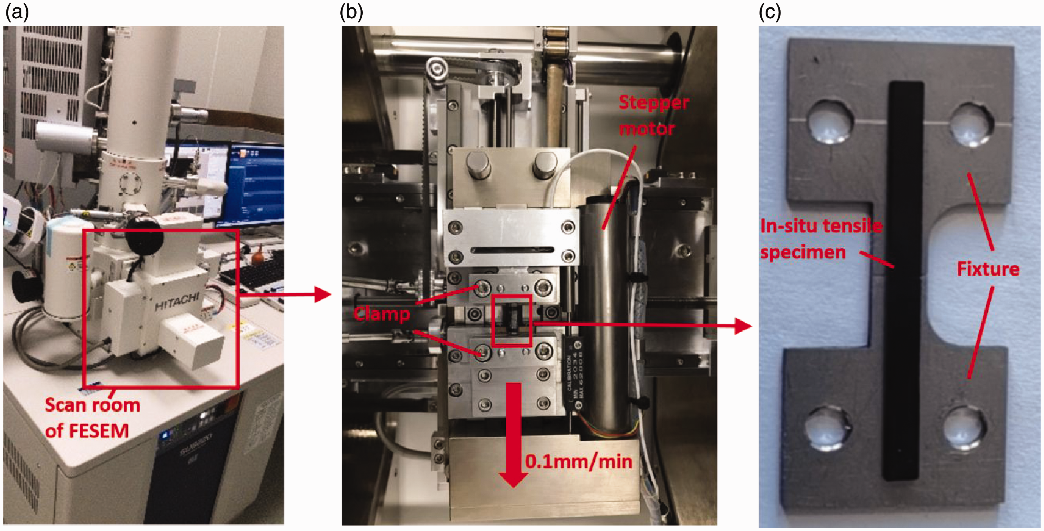
Transverse tensile testing equipment: (a) field emission scanning electron microscope (FESEM) Hitachi 8220; (b) in situ stretching table and (c) fixture.
A multiscale analysis method for transverse mechanical property prediction
In this section, a multiscale analysis method was developed to predict the transverse mechanical properties of unidirectional fiber composites. The multiscale analysis method includes three scales: microscale, mesoscale, and macroscale, as shown in Figure 5. At the microscale, an interfacial cohesive zone model based on atomic potential energy was established for the interface, as the interfacial interaction between the fiber and the matrix is actually the interaction of carbon atoms and epoxy molecules. At the mesoscale, a unit cell model including fiber, matrix, and interface was established to calculate the distribution of strain and stress fields by applying periodic boundary conditions. Assuming that the unidirectional fiber composite is uniform and orthotropic at the macroscale, the homogenization method was used to calculate the equivalent flexibility matrix by using the average stress and the average strain of the unit cell to predict the transverse stiffness. The failure criteria and the damage degradation model were adopted to calculate the average stress–strain curve of the unit cell to realize the transverse strength prediction.
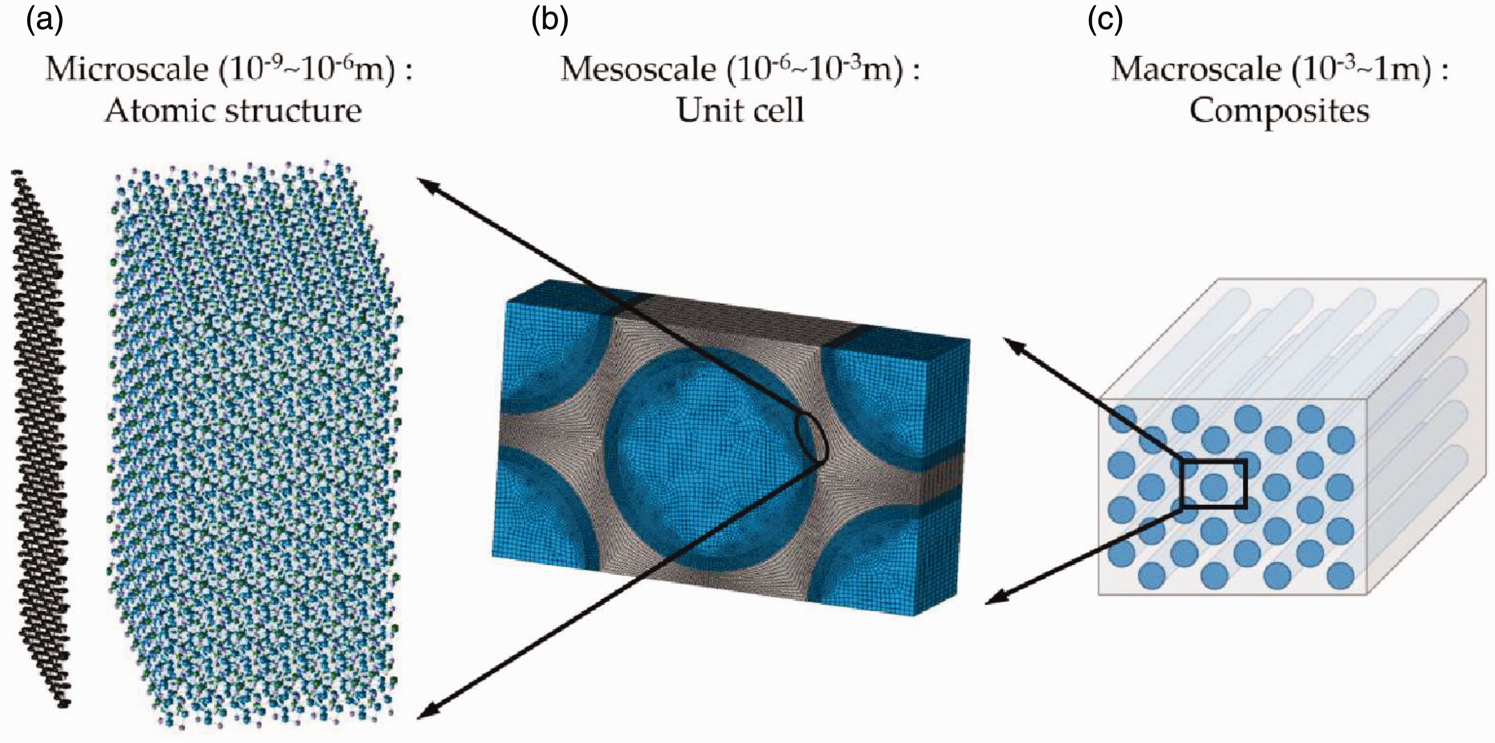
Schematic diagram of the multiscale analysis method: (a) microscale: atomic structure; (b) mesoscale: unit cell and (c) macroscale: uniform composites.
Microscale: an interfacial cohesive zone model based on atomic potential energy
For the carbon fibers without surface modification, the Van der Waals force between the carbon atoms and epoxy molecules is the main force in the interface,42
–44 as shown in Figure 6, and the Van der Waals interactions can be represented by the Lennard–Jones 6–12 potential as

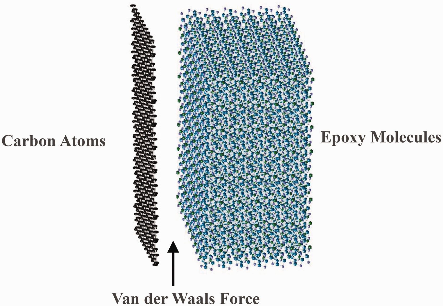
Van der Waals interactions between carbon atoms and epoxy molecules.
An interfacial model of the interaction between the carbon atom layer and epoxy is established, as shown in Figure 7. We use 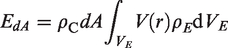

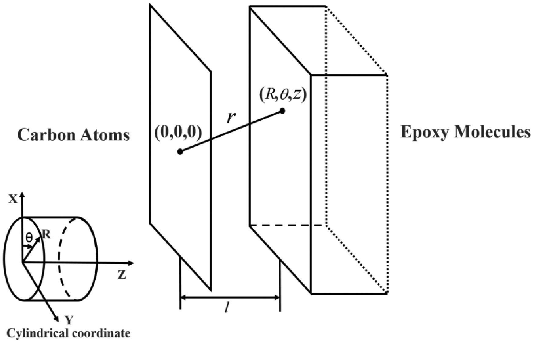
An interfacial model of the interaction between the carbon atom layer and epoxy.
The cohesive energy 
We can calculate 
Considering the opening displacement 
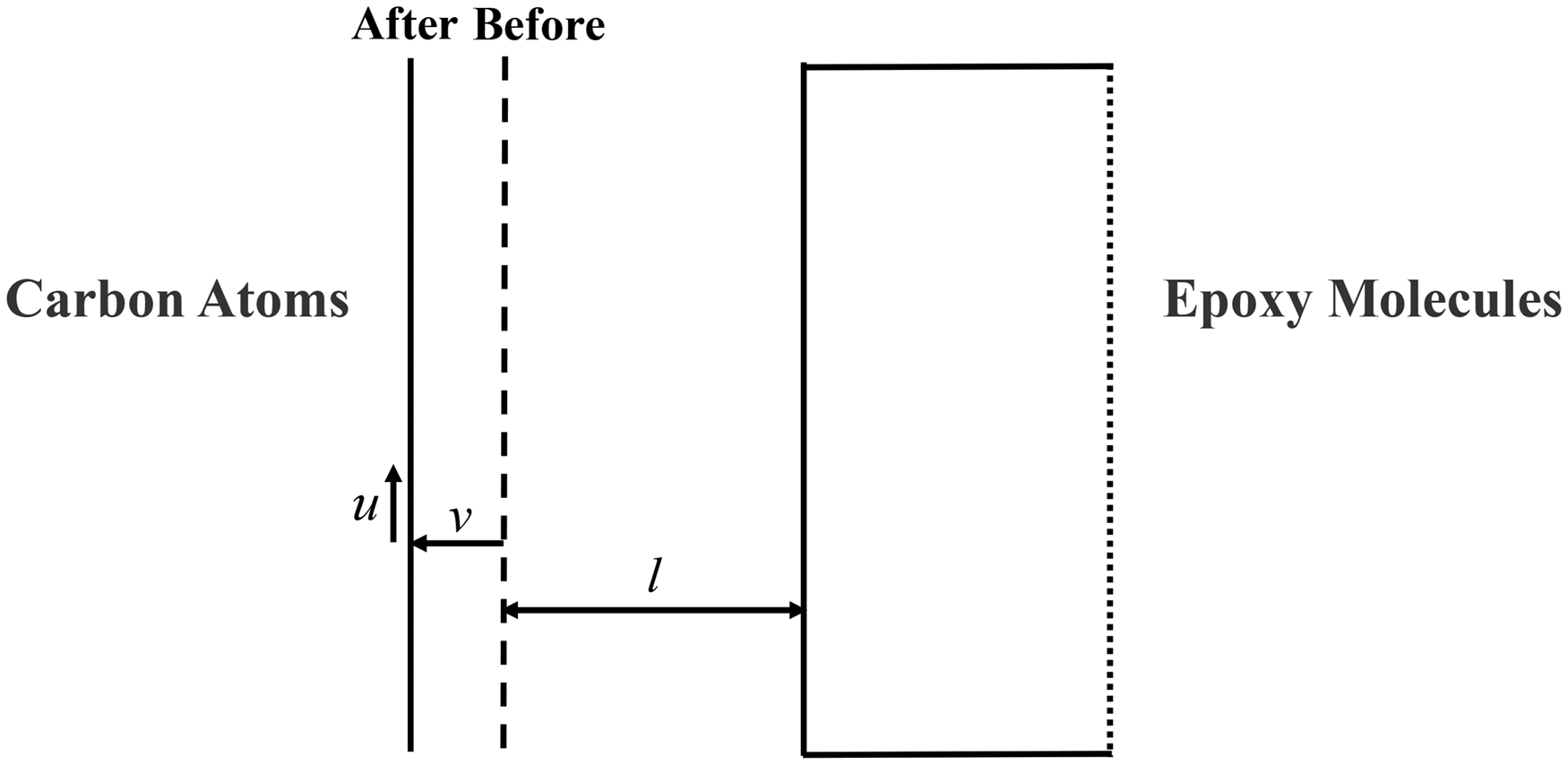
Schematic diagram of opening and sliding displacements of the carbon atom layer.
Equation (5) is independent of the sliding displacement
Therefore, the shear cohesive stress is obtained from Equation (5) as

The tensile cohesive stress can be given by

Equations (6) and (7) give the interfacial cohesive zone model for the interface based on the Van der Waals force.
From Equations (6) and (7), four key parameters (initial slope 



The ICZM in Equation (7) can be rewritten in terms of the cohesive strength 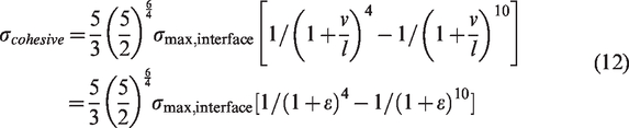
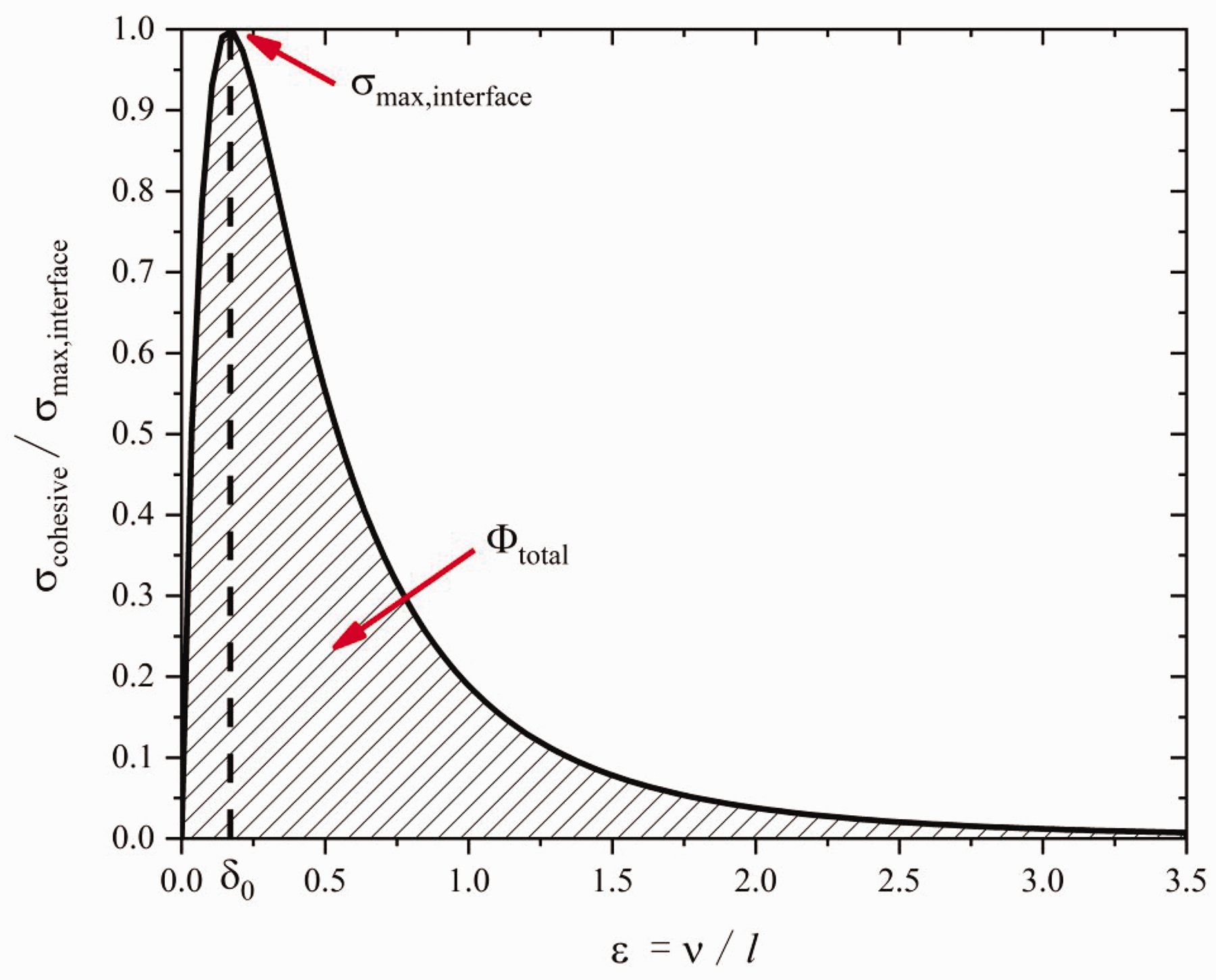
Normalized interfacial cohesive zone model (ICZM) of the interface between carbon fibers and epoxy.
Mesoscale: unit cell model
Unit cell geometry model
It is always assumed that fibers are distributed periodically in the matrix because the unidirectional fiber composite is a transversely isotropic material. The hexagonal arrangement can reflect the transverse isotropy of the composite. Therefore, a hexagonal arrangement was adopted, as shown in Figure 10.
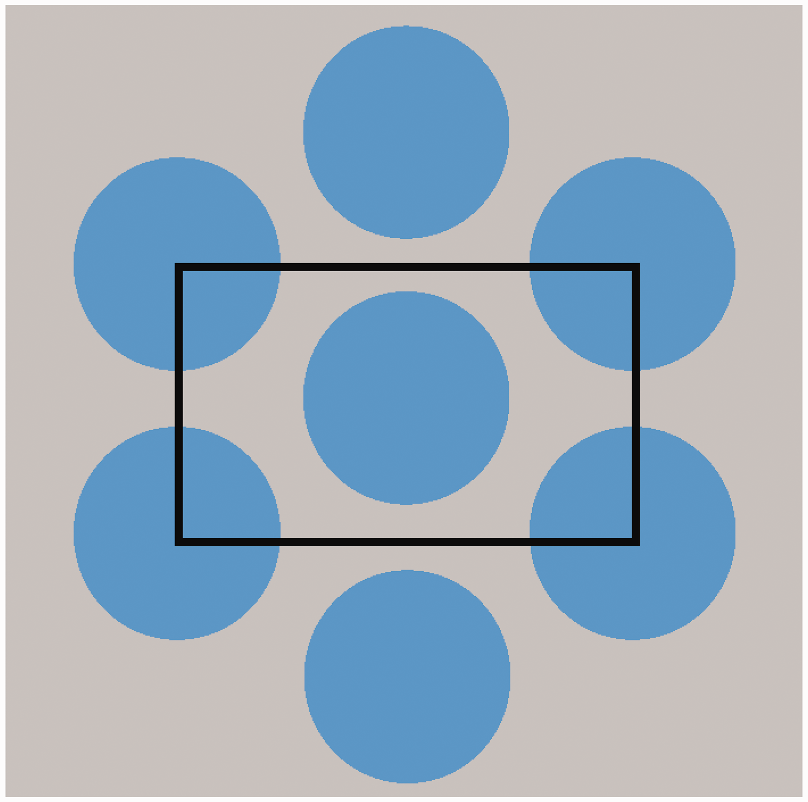
Schematic diagram of the hexagonal arrangement.
The unit cell geometry model is shown in Figure 11, wherein
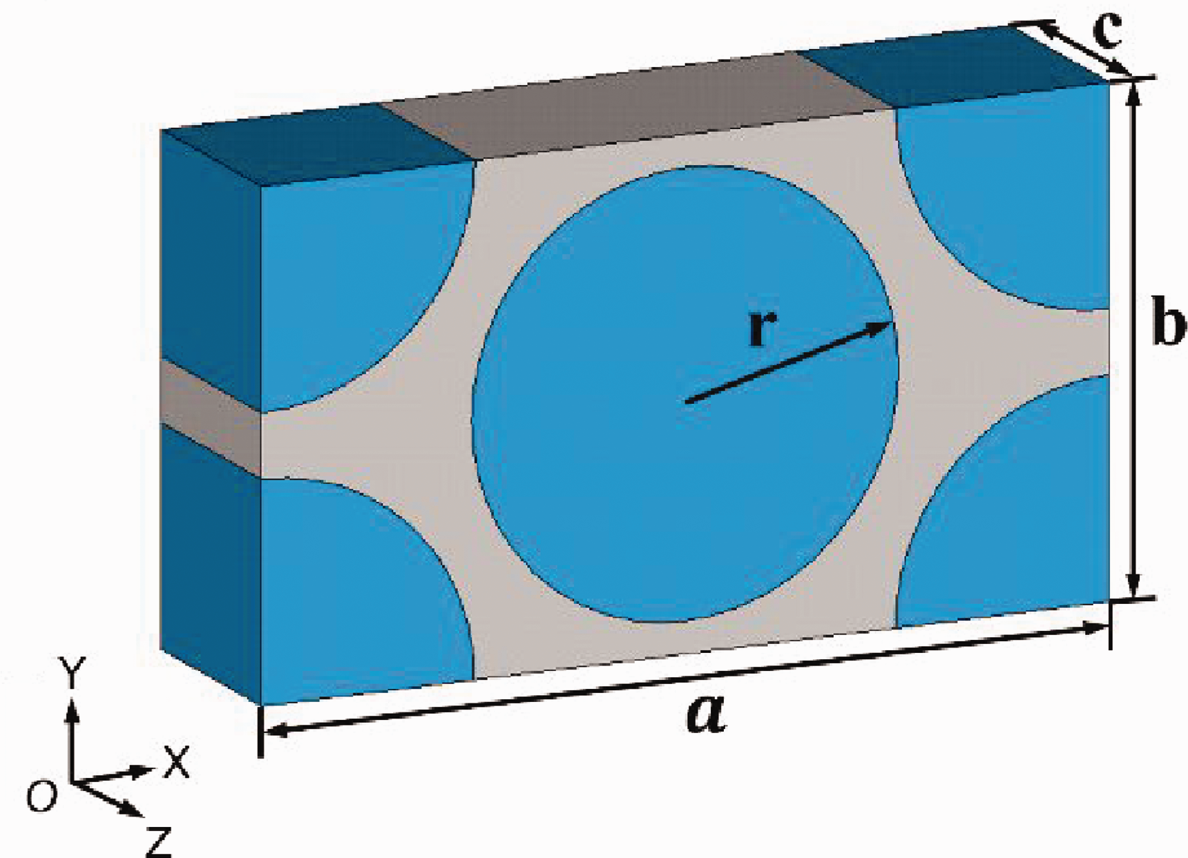
Unit cell geometry model.
Periodic boundary conditions
Xia and Zhang
14
proposed an explicit unified form of boundary conditions suitable for the parallelepiped periodic representative volume element, which is given by

For the unit cell models that are subjected to transverse loadings, as shown in Figure 12, equation (13) can be specified as in Table 2. In Table 2,
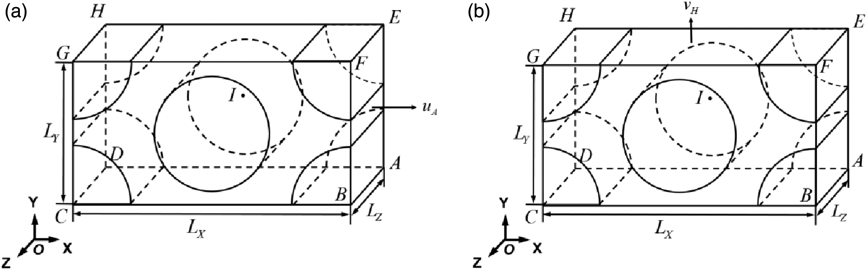
Unit cell models that are subjected to transverse loadings: (a) X direction and (b) Y direction.
Periodic boundary conditions under two transverse loadings

Macroscale: homogenization method, failure criteria, and damage degradation model
Homogenization method
The homogenization method47 –51 that emerged in the 1970s can be used to analyze physical systems of two or more scales. After several years of development, the homogenization method has been successfully applied to many physical and engineering fields and has become a commonly used method for analyzing the mechanical properties of unidirectional fiber composites.
The average stress and average strain can be expressed using the homogenization method into the unit cell:


The macroscopic properties of the unidirectional fiber composite can be considered transversely isotropic, so the macroscopic stress–strain relationship can be expressed as


Failure criteria and damage degradation model
The selection of the proper failure criteria for fiber and matrix is of great importance for the modeling formulation. The maximum stress theory is adopted for the fiber, as carbon fiber is an anisotropic material. The maximum principal stress theory is applied for the matrix because epoxy is an isotropic material.
To simulate the damage evolution process, the current stress state of each integration point is first obtained through calculation. Then, by comparing the current stress state with the corresponding failure criterion, the material properties are reduced at each failed integration point to values representing the particular type of damage that has occurred.52
–55 When failure occurs, the degradation is applied only on the elastic moduli by multiplying these values with a degradation factor
The above degradation scheme, together with the failure criteria and the damage degradation model, was programmed into a user-defined material subroutine by ANSYS APDL.
Application of the multiscale analysis method
Based on the above multiscale analysis method, finite-element modeling of the unit cell with the ICZM was established with ANSYS. To make a comparison, two other finite-element modelings were established: the unit cell without interface and the unit cell with the bilinear cohesive zone model (BCZM).
Material parameters
The material properties of the two components are listed in Table 1. The ICZM (equation (12)) was adopted for the interface and implemented by user programmable features subroutine userCZM. The values of the ICZM parameters are given as follows:
Values of BCZM parameters

BCZM: bilinear cohesive zone model.
Geometric parameters and finite-element mesh
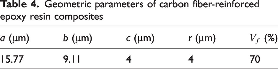
The unit cell geometry model is shown in Figure 11, and the geometric parameters are listed in Table 4.
Geometric parameters of carbon fiber-reinforced epoxy resin composites
The finite-element model is shown in Figure 13. The blue elements represent the fiber (Figure 13(a)), the gray elements denote the matrix (Figure 13(b)), and the green elements are the interface (Figure 13(c)). The Solid 185 element was adopted for the fiber and matrix. To predict the damage path, the fiber and matrix elements near the interface were refined. The Inter 205 was adopted for the interface. To apply periodic boundary conditions, the mesh of the opposite faces of the unit cell should be the same.
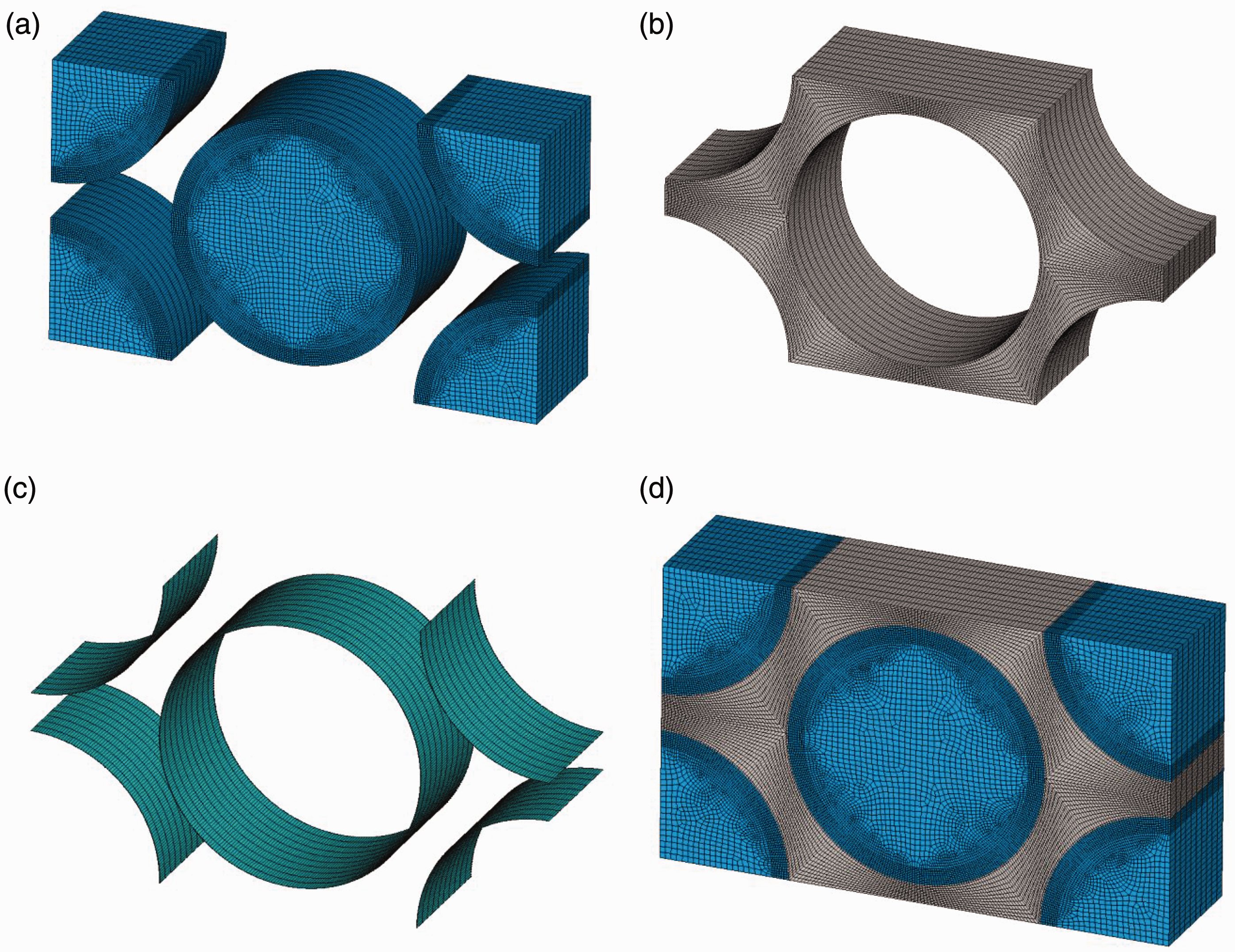
Unit cell finite-element model: (a) fiber; (b) matrix; (c) interface; and (d) unit cell.
Boundary conditions
In these finite-element modeling studies, only two loading conditions have been applied to the unit cell shown in Figure 12: (a) transverse loading in the X direction, and (b) transverse loading in the Y direction. The periodic boundary conditions applied to the finite-element model are given in Table 2.
Results
Comparison with experimental results
To validate the multiscale analysis method, the transverse mechanical properties are investigated with the proposed model, the unit cell without an interface and the unit cell with BCZM. The numerical predictions are then compared with the experimental results, as indicated by Table 5. Table 5 indicates that the errors of the transverse modulus, strength, and ultimate strain predicted by the ICZM are only 0.73%, –0.37%, and –2.50%, respectively, which shows that the multiscale analysis method can accurately predict the transverse mechanical properties. In contrast, for the unit cell without an interface, the errors of these mechanical properties are 6.70%, 35.19%, and 11.25%, respectively, which means that the interface has a substantial effect on the transverse modulus, strength, and ultimate strain. For the unit cell with the BCZM, the errors of mechanical properties are 2.30%, 6.41%, and –8.75%, respectively, which demonstrates that the ICZM predictions are more accurate than BCZM predictions.
Comparison between the experimental results and predictions for the transverse mechanical properties

BCZM: bilinear cohesive zone model; ICZM: interfacial cohesive zone model.
A comparison of the predictions and experimental results for the transverse tensile stress–strain curve is shown in Figure 14. The stress–strain curve from the ICZM is in great agreement with that in the experiments, which means that the ICZM can reflect the nonlinearity of epoxy matrix composite materials. In contrast, the stress–strain response for the simulations without an interface is linear, because the interface is not considered; the stress–strain response for the simulations with BCZM is linear too, because the linear cohesive zone model cannot reflect the effect of interfacial microscopic properties on macroscopic mechanical behavior.
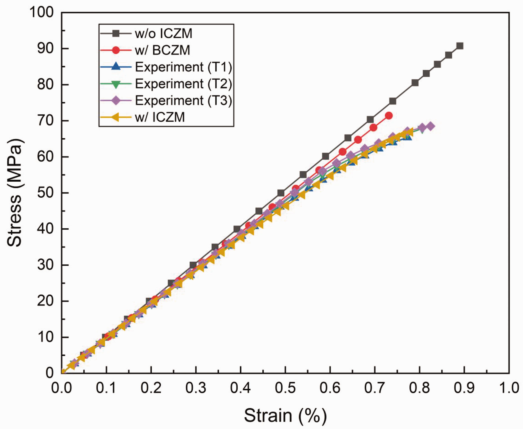
Comparison of the predictions and experimental results for the transverse tensile stress–strain curve.
Damage evolution
Figure 15 shows the FESEM micrographs of the fracture surfaces for the in situ tensile specimen. Figure 15(a) illustrates that the main failure mode is matrix cracking when composite laminates are under transverse tensile load. Figure 15(a) also shows that a small amount of carbon fiber/matrix debonding occurs. Figure 15(b) shows that there are two damage evolution paths: damage expands from the interface to the matrix (damage evolution path 1); and damage expands along the interface until the fiber and matrix are debonded (damage evolution path 2). The main damage evolution path is damage evolution path 1.
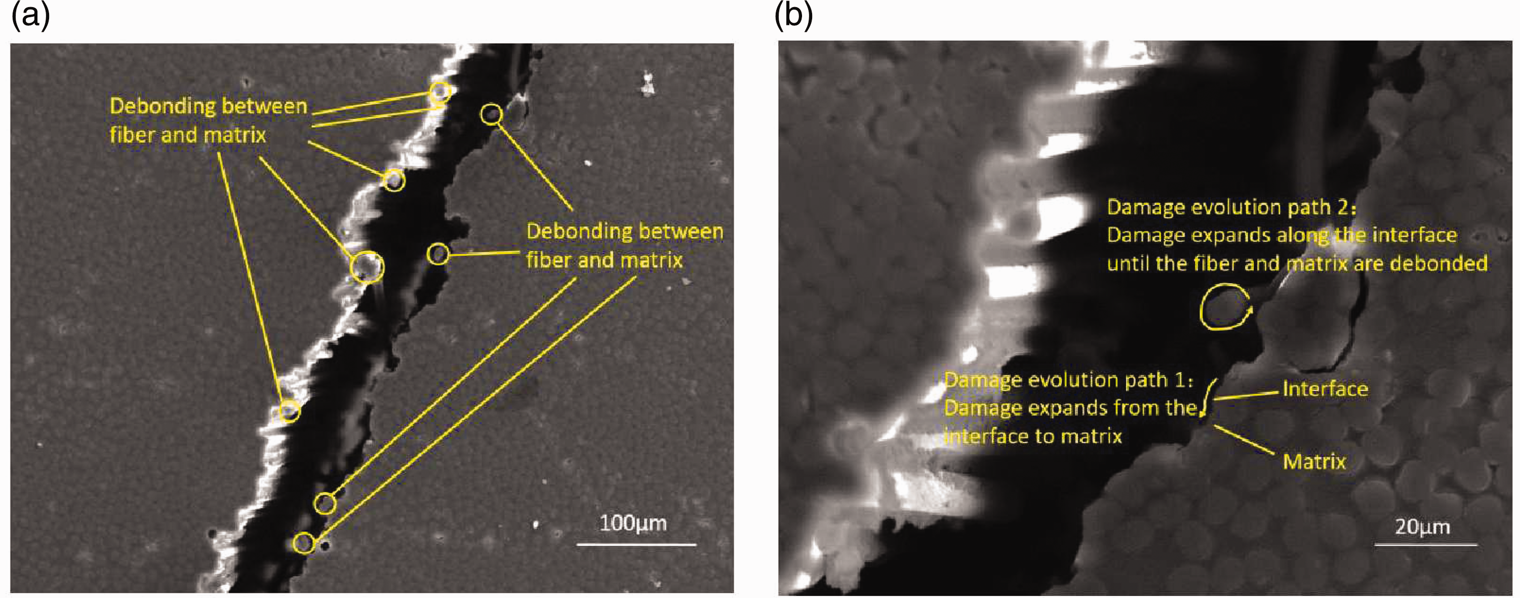
Field emission scanning electron microscope (FESEM) micrographs of the fracture surfaces for the in situ tensile specimen: (a) 100 μm and (b) 20 μm.
A comparison of the predictions and experimental results for the damage evolution path is shown in Figure 16. Figure 16 shows that the predicted damage evolution path is consistent with the experimental results, which means that the multiscale analysis method can accurately predict the damage evolution path.
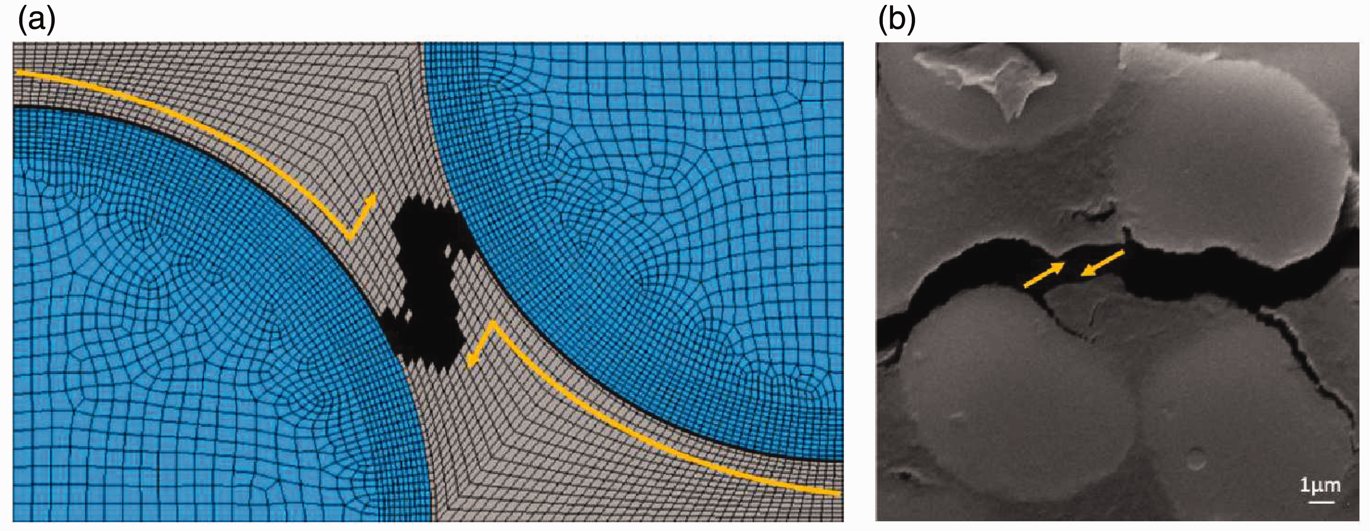
(a) Prediction and (b) experimental result of the damage evolution path.
Discussion
The microscopic properties of the interface have a significant effect on the macroscopic mechanical properties of composites. To study the effect of the interfacial strength of the ICZM on the macroscopic mechanical properties, the transverse stress–strain curves under X direction and Y direction loadings were calculated by increasing the interfacial strength from 13 MPa to 93 MPa, as shown in Figures 17 and 18. Five values of interfacial strength are selected (
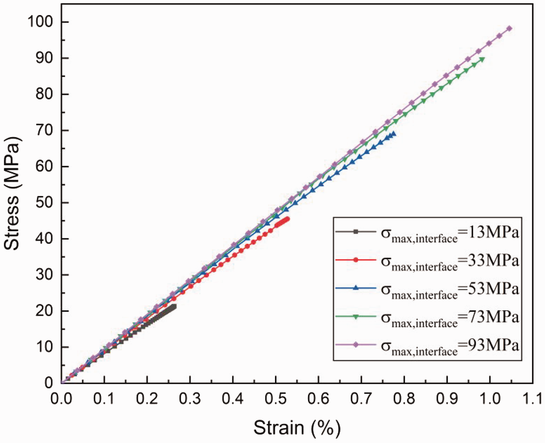
Transverse stress–strain curves under X direction loading with different interfacial strength values.
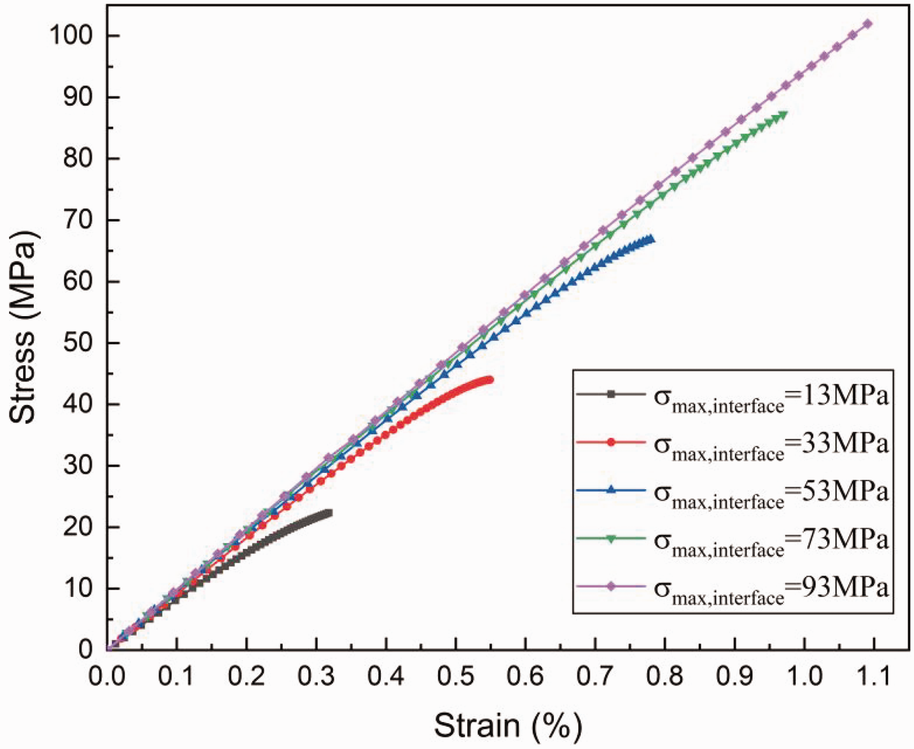
Transverse stress–strain curves under Y direction loading with different interfacial strength values.
Effect of the interfacial strength on the transverse modulus
The relationship between the transverse modulus and the interfacial strength is illustrated in Figure 19. Figure 19 shows that decreasing the interfacial strength has a greater effect on the transverse modulus than increasing the interfacial strength. The descent rate of the transverse modulus ranges from 3.2% to 9.4% when the interfacial strength decreases 20 MPa, whereas the ascent rate of the transverse modulus is only 1.0% to 1.7% when the interfacial strength increases 20 MPa. Therefore, the reduction in the interfacial strength caused by the existence of many microdefects can greatly reduce the transverse modulus.
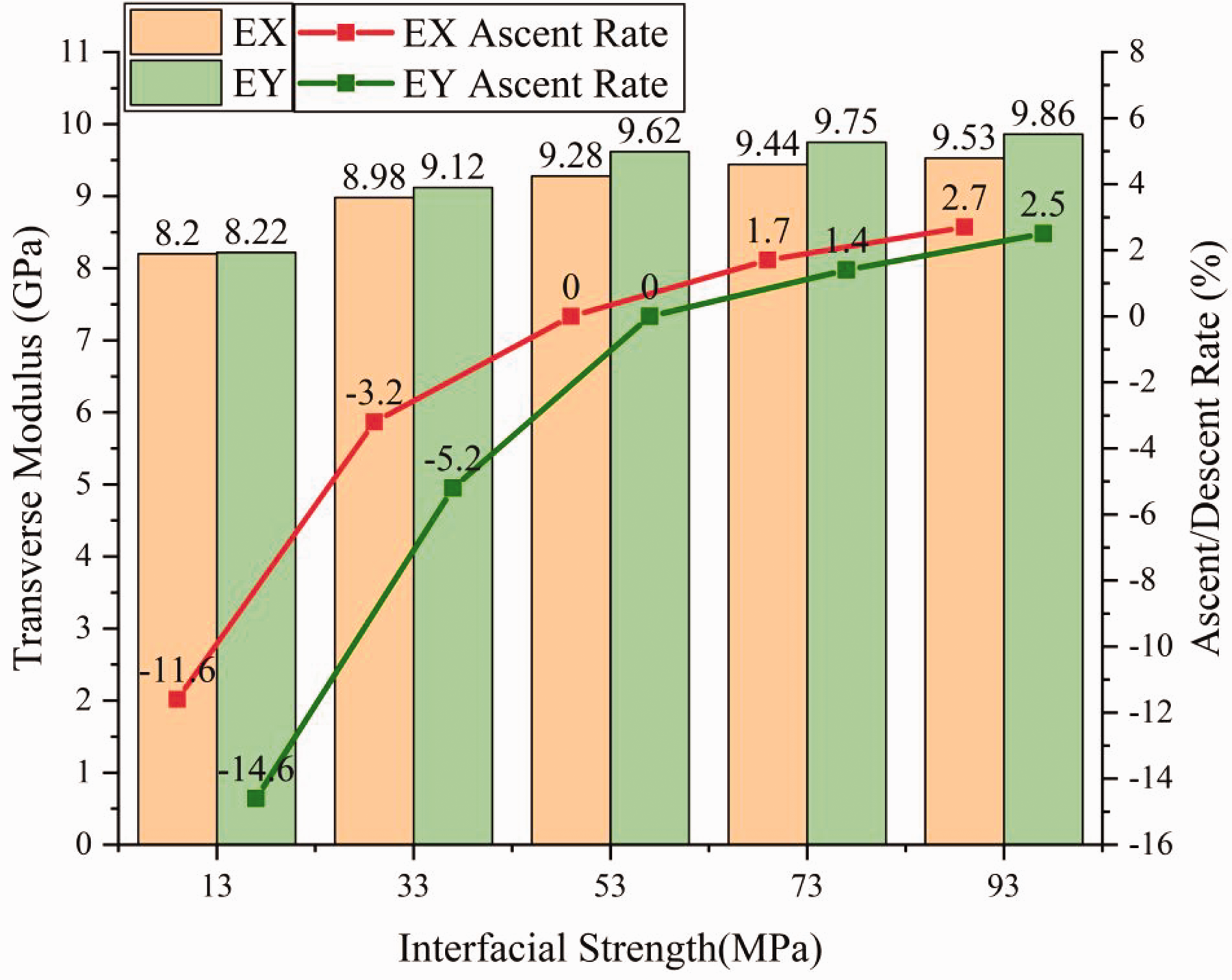
Relationship between the transverse modulus and the interfacial strength.
Equations (8) and (9) show that the interfacial strength is proportional to the initial slope of the interfacial constitutive equation. Therefore, decreasing the interfacial strength can reduce the interfacial modulus and, thus, the composite transverse modulus. Similarly, increasing the interface strength can increase the interface modulus and thus the composite modulus.
Effect of the interfacial strength on the transverse strength
The relationship between the transverse strength and the interfacial strength is illustrated in Figure 20. Figure 20 shows that the effect of the interfacial strength on the transverse strength is greater than that on the transverse modulus. The ascent and descent rates of the transverse strength are approximately 47.1% and 68.4% when the interfacial strength increases and decreases by 40 MPa, whereas these rates are 2.6% and 13.1% for the transverse modulus, respectively. Therefore, improving the performance of the composite interface can greatly improve the corresponding transverse strength.
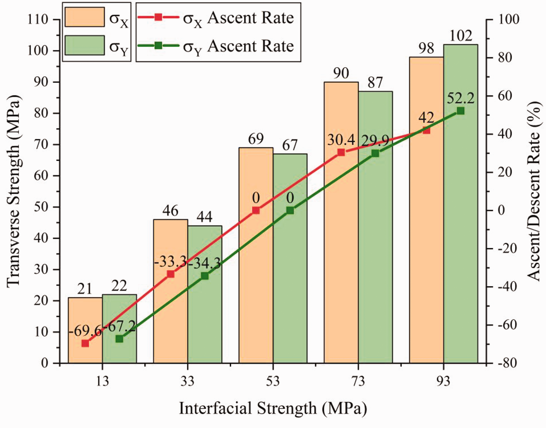
Relationship between the transverse strength and the interfacial strength.
Figure 20 also shows that decreasing the interfacial strength has a greater effect on the transverse strength than increasing the interfacial strength. The descent rate of the transverse strength ranges from 32.9% to 36.3% when the interfacial strength decreases 20 MPa, whereas the ascent rate of the transverse strength ranges from 11.6% to 30.4% when the interfacial strength increases 20 MPa. Therefore, the reduction in the interfacial strength caused by the existence of many microdefects can greatly reduce the transverse strength.
Effect of the interfacial strength on the transverse ultimate strain
The relationship between the transverse ultimate strain and the interfacial strength is illustrated in Figure 21. Figure 21 shows that the effect of the interfacial strength on the transverse ultimate strain is greater than that on the transverse modulus. The ascent and descent rates of the ultimate strain are approximately 37.2% and 63.5% when the interfacial strength increases and decreases by 40 MPa, respectively, whereas these rates are 2.6% and 13.1% for the transverse modulus, respectively. Therefore, improving the performance of the composite interface can greatly improve the corresponding transverse ultimate strain.
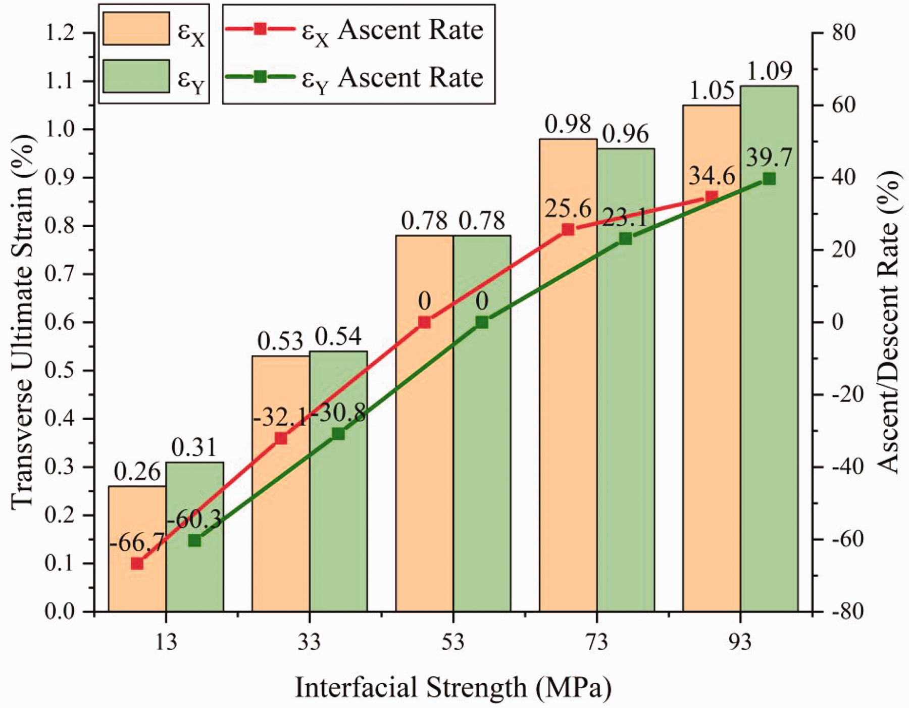
Relationship between the transverse strength and the interfacial strength.
Figure 21 also shows that decreasing the interfacial strength has a greater effect on the transverse ultimate strain than increasing the interfacial strength. The descent rate of the transverse ultimate strain ranges from 29.5% to 34.6% when the interfacial strength decreases 20 MPa, whereas the ascent rate of the transverse modulus ranges from 9.0% to 25.6% when the interfacial strength increases 20 MPa. Therefore, the reduction in the interfacial strength caused by the existence of many microdefects can greatly reduce the transverse ultimate strain.
Conclusions
Carbon fiber-reinforced epoxy matrix composite laminates have been widely used in the case of advanced aero-engines, due to their high specific mechanical properties and mature production technology. A multiscale analysis method is proposed for predicting the transverse mechanical properties of unidirectional fiber composites, and verified by the transverse tensile test and in situ tensile test. By using the multiscale analysis method, the effect of the interfacial strength of the ICZM on the macroscopic transverse mechanical properties is discussed. The multiscale analysis method proves to be effective in accurately predicting the transverse mechanical properties of composites and provides insights into the interfacial strength’s role in these properties. Some key conclusions of this work can be summarized as follows:
The maximum errors of all results between the tests and predictions are less than 3%, and the predicted damage evolution path is consistent with the experimental result, validating the accuracy of the multiscale analysis method developed in this paper. The stress–strain curve from the ICZM is in great agreement with that in the experiments, which means that the ICZM can reflect the nonlinearity of epoxy matrix composite materials. The ascent rates of the transverse strength, ultimate strain, and modulus are 47.1%, 37.2%, and 2.6% when the interfacial strength increases by 40 MPa, respectively. The descent rates of the transverse strength, ultimate strain, and modulus are 68.4%, 63.5%, and 13.1% when the interfacial strength decreases by 40 MPa, respectively. It means that the interfacial strength has a more significant effect on the transverse strength and ultimate strain than on the transverse modulus. Therefore, improving the performance of the composite interface can greatly improve the transverse strength and ultimate strain. The descent rates of the transverse strength, ultimate strain, and modulus are approximately 34.6%, 32.1%, and 6.3% when the interfacial strength decreases by 20 MPa, respectively. The ascent rates of the transverse strength, ultimate strain, and modulus are 21.0%, 17.3%, and 1.4% when the interfacial strength increases by 20 MPa, respectively. It means that decreasing the interfacial strength has a greater effect on the transverse modulus, strength and ultimate strain than increasing the interfacial strength. Therefore, the reduction in the interfacial strength caused by the existence of many microdefects can greatly reduce the transverse modulus, strength, and ultimate strain.
Footnotes
Acknowledgements
This work has been supported by the Key Laboratory of Aero-engine Thermal Environment and Structure, Ministry of Industry and Information Technology (no. XCA1700205).
Declaration of conflicting interests
The author(s) declared no potential conflicts of interest with respect to the research, authorship, and/or publication of this article.
Funding
The author(s) disclosed receipt of the following financial support for the research, authorship, and/or publication of this article: This work was partially supported by the Postdoctoral Fellowship Program of CPSF(GZC20232263), the National Natural Science Foundation of China (52305165) and the project “Research on resin-based composites fan casing containment design technique” provided by AECC.
