



Abstract
Reducing energy consumption during textile production processes has currently become one of the key concerns. In order to design the nozzle of the vortex spinning machine with reduced air consumption, numerical simulation of the airflow in the nozzle is performed to investigate the effect of the length and the inlet diameter of the conical chamber in the intermediate section of the vortex tube on the air consumption and the mechanical energy characteristics of the airflow. A spinning experiment conducted to measure the flow rate and yarn tenacity is adopted to verify the numerical simulation results. The simulation results show that the air consumption of the nozzle is insignificantly affected as the length increases from 7.3 mm to 7.7 mm, while a decreasing trend has been found as the length increases from 7.7 mm to 8.1 mm. As the inlet diameter increases from 4.6 mm to 5.0 mm, the air consumption of the nozzle increases monotonically. The mechanical energy of airflow in the nozzle exhibits a minor difference between cases of lengths of 7.3 mm, 7.5 mm, and 7.7 mm, while it decreases significantly in cases of lengths of 7.9 mm and 8.1 mm. The mechanical energy of airflow in the vortex chamber increases as the inlet diameter increases. The experimental results are consistent with the numerical predictions. This work is expected to provide a reference for the design of the vortex spinning nozzle and an approach to reducing the energy consumption in the yarn production process.
Keywords
As a new spinning technology, vortex spinning has attracted widespread attention due to its characteristics of high speed, short process, and reduced labor intensity. Compared with other yarns, the vortex yarn has the advantages of better evenness, lower hairiness, and superior abrasion resistance, and so on.1,2 Airflow plays an important role in the process of yarn formation in this technology. Vortex spinning employs a high-speed swirling airflow injected into the nozzle through several tangential injectors on the vortex tube to achieve twist insertion. Under the action of the swirling airflow, the drafted fiber bundle is sucked into the nozzle through the fiber guiding element, and is then twisted into a yarn with a layered structure consisting of twistless fibers in the core wrapped by helical wrapper fibers in the sheath.3,4 Furthermore, swirling airflows are also widely adopted in many other industrial applications, such as enhancing the mixing between fuel and oxidant in combustion systems, 5 separating particles in cyclones, 6 and improving the coefficient of performance in cooling systems. 7 However, there exist complex phenomena in swirling flows such as vortices and shear effects, which can affect the efficiency of the industrial production. Fully revealing the mechanism of swirling flow is of great significance to improving manufacturing efficiency and upgrading product quality.
Due to the advantages of high accuracy and low cost of numerical simulation, a great number of numerical studies on swirling flows in the engineering field have been carried out in recent years.8–12 In the process of vortex spinning, the flow characteristics have an impact on the dynamic behavior of the fibers, consequently influencing the structure and properties of the yarn. Therefore, it is critical to predict the performance of the vortex spun yarn by investigating the flow field in the vortex spinning nozzle. Li et al. 13 adopted the numerical simulation to investigate the effect of airflow characteristics in the vortex tube with different structures on yarn performance. The results indicated that there is a transition region between the cylindrical and conical cavities inside the tube, in which a large negative pressure and high axial and tangential velocities can be generated. This flow characteristic is conducive to the formation of the open-end trailing fibers and twist insertion. Eldeeb and Mouckova 14 numerically simulated the effect of nozzle pressure on the tenacity of Rieter air jet yarn using a computational fluid dynamics (CFD) analysis based on the finite volume method. The results of the study indicated that increasing the nozzle pressure can increase the tangential and axial velocities inside the nozzle, which is beneficial for the fiber separation and wrapping process, while at an extra high pressure, the tangential velocity becomes so high that the control of fiber motion will become difficult. Zou et al. 15 simulated the airflow characteristics of the vortex spinning nozzle with different jet orifice angles, the outer diameters of the hollow spindle and the distances from the inlet of the nozzle block to the inlet of the hollow spindle. Yan et al. 16 developed a novel hollow spindle with spiral grooves and numerically analyzed the airflow pattern in the region near the spiral grooves. The results show that the spiral grooves can help guide the swirling airflow moving downstream through the conical cavity of the twisting chamber, resulting in the increase of the tangential, axial and radial velocities of airflow. Phung et al. 17 performed a CFD analysis on the effects of the supplied air pressure and the exhaust air pressure on the fiber suction force and twist torque at the starting time of the spinning process in the vortex spinning machine. As can be seen, the process and nozzle structural parameters can influence the airflow characteristics inside the nozzle, which in turn affects the fiber motion during the yarn formation process. However, the numerical simulations of the airflow inside the vortex spinning nozzle in existing works are confined to predicting the yarn strength based on the velocity and pressure characteristics. Few studies have focused on investigating the flow-related energy characteristics in vortex spinning up to now. In the yarn production process of vortex spinning, there exist complex energy characteristics that are related to the yarn performance considering the high speed, compressible, viscous characteristics of the airflow inside the spinning nozzle. As the twist insertion into the fiber strand mainly takes place in the annular region between the conical wall of the intermediate section of the vortex tube and spindle, the related structural parameters of the vortex tube will therefore exert a significant influence on both the airflow characteristics and yarn performance. In particular, the effect of the length and inlet diameter of the conical chamber in the intermediate section of the vortex tube on the internal airflow characteristics has not been reported in previous studies. As a result, further investigation on these structural parameters is urgently required.
The energy consumption is widely concerned about and studied in the engineering field. In the incompressible fluid systems, the method of studying pressure drop and velocity distribution to optimize energy consumption is widely adopted. 18 The entropy production theory based on a reliable theoretical foundation has been applied to complex closed systems. 19 In addition, some researchers have directly analyzed the variation of the mechanical energy in the flow field to investigate the energy consumption and conversion. 20 However, the flow rate through the injectors of nozzles is the main indicator of energy consumption in the vortex spinning system.21–23 However, an investigation related to energy consumption in the vortex spinning process has not been conducted. As reducing the flow rate of the nozzle can reduce the energy costs in the vortex spinning system, it is imperative to analyze the air consumption inside the vortex spinning nozzle.
Although a number of studies have been conducted to simulate the flow field in the vortex spinning nozzle, the energy consumption and energy characteristics have not been investigated before. Aimed at developing the vortex spinning nozzle with reduced energy consumption and high twist-insertion efficiency, a three-dimensional numerical simulation of the flow field in the vortex spinning nozzle is conducted in this paper to investigate the effects of two structural parameters – the length and the inlet diameter of the conical chamber in the intermediate section of the vortex tube, on the flow pattern and energy characteristics. Measurement of the airflow rate and yarn spinning experiment are conducted qualitatively to validate the numerical results. This work is expected to provide a foundation for reducing the energy consumption in the textile production process, and a reference for optimizing the structural parameters of the key components of textile machines involving airflow.
Numerical model and methods
Geometry of vortex spinning nozzle
During the spinning process, the airflow is injected into the vortex chamber through the tangential injectors, generating a high-speed swirling airflow. The drafted fiber bundle is sucked into the nozzle through the spiral guiding passage. The trailing portions of some fibers are separated from the fiber bundle and become free driven by the swirling airflow. The leading portions of these fibers are pulled into the yarn passage of the spindle, while the trailing portions are expanded and whirled over the spindle tip to insert twist into the vortex yarn under the action of the swirling airflow.24,25
The schematic diagram of the nozzle structure of the vortex spinning system is shown in Figure 1. The main components of the nozzle include the fiber guiding element, vortex tube, spindle, yarn delivery tube and nozzle casing. There is a spiral guiding surface and a guiding needle on the fiber guiding element. The spiral guiding passage is formed between the spiral guiding surface and the nozzle casing. Downstream of the fiber guiding element, there exists a vortex tube with four tangential injectors that incline toward the downstream so that an acute angle is formed between each injector and the cross-section of the nozzle. In the inlet region of the vortex tube, there is a hole with a large diameter and a very small depth which is used to support the fiber guiding element. A cylindrical chamber is formed in the upstream region inside the vortex tube, while two conical chambers with different cone angles are connectively formed in the intermediate and downstream regions. A step where the injector exits are located is formed at the junction of the cylindrical chamber and the conical chamber. The spindle with a conical-shaped tip is mounted coaxially inside the downstream region of the vortex tube. A yarn passage is formed through the spindle. In order to facilitate the yarn drawing-in process, the yarn delivery tube is equipped with five injectors that are perpendicular to the axis. The inlet portion of the yarn delivery tube is coaxially inserted into the internal chamber of the spindle and is tightly assembled with it.
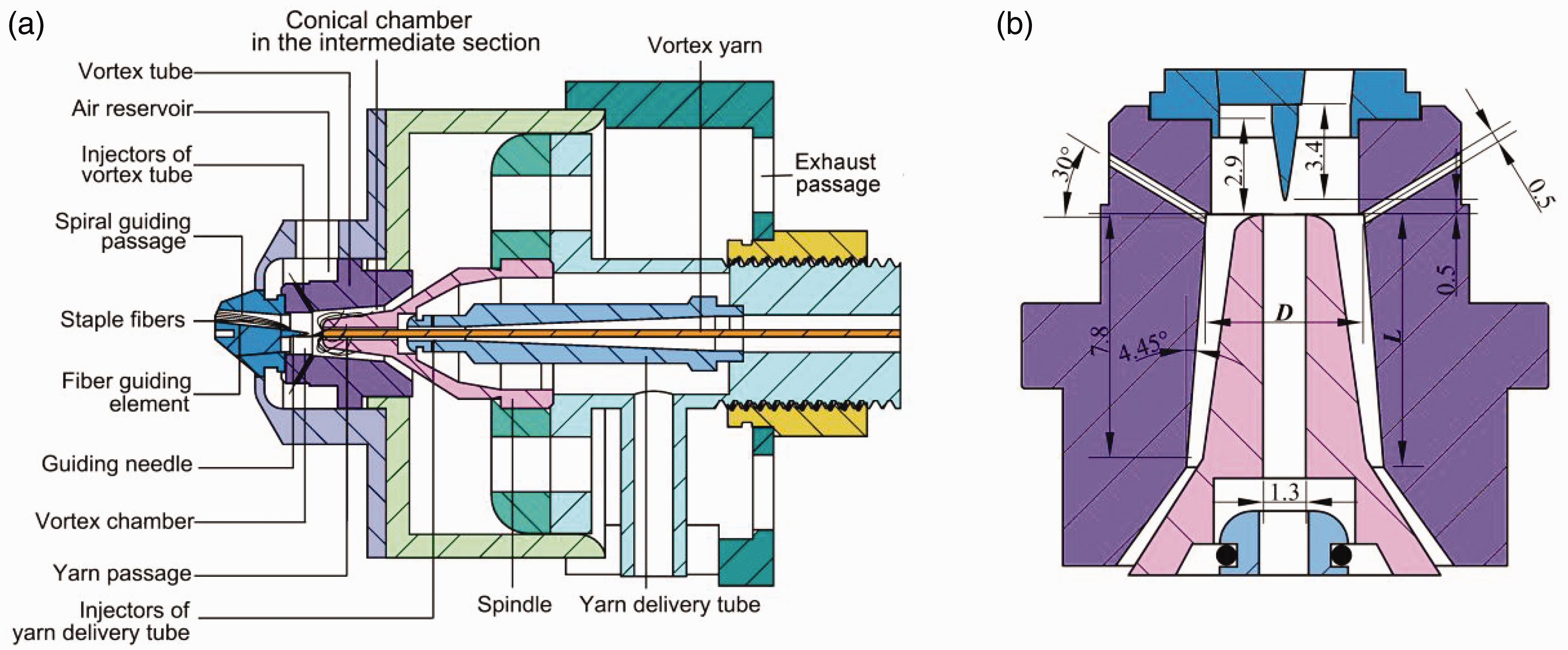
Schematic diagrams of the nozzle structure of the vortex spinning system: (a) a general view and (b) a magnified view.
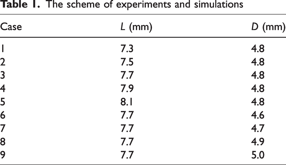
To reduce the energy consumption and optimize the structural parameters, the effects of the length (L) and inlet diameter (D) of the conical chamber in the intermediate section of the vortex tube, as shown in Figure 1(b), on the airflow characteristics inside the nozzle are investigated. In the study, when the length and inlet diameter of the conical chamber are changed, the angle between the wall of the conical chamber and the nozzle axis remains constant. A total number of nine cases, as listed in Table 1, are employed for the numerical simulation and experiment.
The scheme of experiments and simulations
Numerical model
As the Mach number of the airflow inside the nozzle exceeds 0.3,
26
the compressibility of the flow needs to be considered. The Reynolds number of the airflow inside the nozzle is of the order of 104,24 so that the flow is considered to be in the turbulent regime. In addition, due to the existence of the complex coupling of several streams of secondary flows and air jets, the viscidity of the airflow cannot be ignored. Therefore, the tangentially injected swirling flow in the vortex spinning nozzle is considered to be three dimensional, compressible, viscous and turbulent Newtonian flow. The governing equations can be expressed as



The following equation of the state of perfect gas is adopted:

Considering the advantages of the realizable k−ε model in describing flow with high jet diffusion velocity, strong streamline curvature and vortices, it is adopted in this study to investigate the turbulence characteristics inside the nozzle.
27
In the realizable k−ε model, an improved method is employed to calculate the turbulent viscosity. The exact transport equation of the fluctuating vorticity is used to derive the equation of the turbulence dissipation rate. The transport equations for the turbulence kinetic energy k and its dissipation rate ε are


Boundary conditions and numerical methods
The computational domain of the airflow field adopted in the numerical simulation is composed of the fluid-filled cavity region inside the nozzle casing, including the spiral guiding passage, air reservoir, injectors, vortex chamber, the annular region between the spindle and the vortex tube, yarn passage, and the exhaust passage. The computational domain and boundary conditions are illustrated in Figure 2. A right-handed Cartesian coordinate system is employed with its origin located at the center of the face of the spiral guiding passage inlet. According to the yarn production conditions, the pressure inlet boundary condition is prescribed at the inlet of the air reservoir where the total pressure is set to 0.5 MPa, while pressure outlet boundary conditions are prescribed at the inlet of the spiral guiding passage, outlet of the yarn passage, and the exhaust passage where the air pressure is set to be the atmospheric pressure. A no-slip condition is applied at all the solid walls.
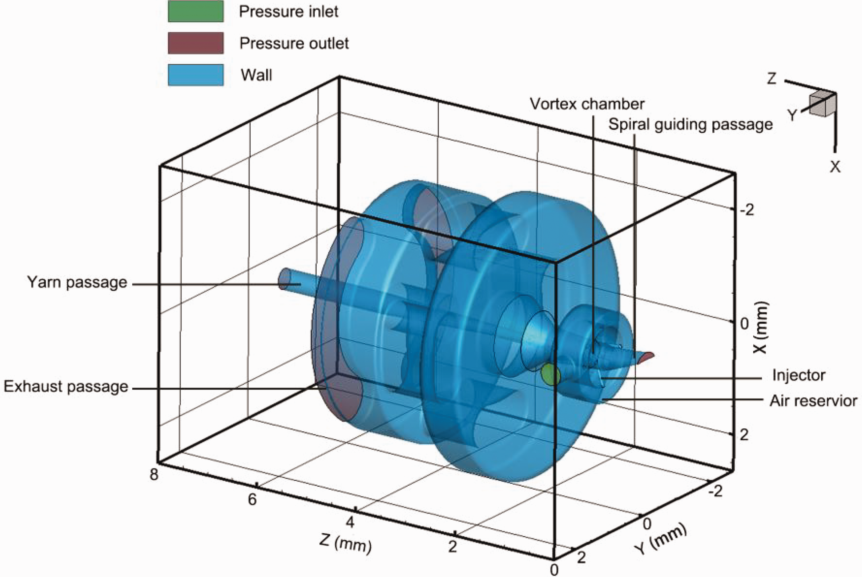
Schematic diagram of the computational domain.
The computational model is solved with ANSYS FLUENT software. The control volume method and second-order upwind scheme are employed to discretize the governing equations. To describe the compressibility of the airflow, the coupled-implicit pressure velocity solver algorithm and the density-based solution method are adopted. In addition, to improve the stability and accuracy of the calculation, the Courant number is set to 2. The solution is considered to be converged when the mass flow rates at the inlet and outlet reach a steady state or when the difference between them is less than 1%.
Mesh generation
As shown in Figure 3, the mesh for computation is generated using the software FLUENT MESHING. To guarantee the computation accuracy and efficiency, a multi-block mesh generation scheme with unstructured tetrahedral grids is adopted. In order to capture the complex interactions of multiple secondary flows, ultrafine tetrahedral mesh elements are employed in the spiral guiding passage, injectors, and the vortex chamber. Fine tetrahedral mesh elements are employed inside the yarn passage as well as the annular region between the spindle and the vortex tube. Coarser mesh elements are employed in the remaining fluid regions.

Mesh generated for the airflow simulation: (a) the perspective view and (b) a magnified view in the cross-section of Y = 0 mm.
Results and discussion
Grid independence check and model verification
In order to find the optimal mesh generation scheme, a grid independence check is carried out by taking case 3 as an example. The monitoring plane of velocity component is indicated by a red line in Figure 3. Three levels of grids containing 1,187,510, 1,805,512 and 2,388,282 cells, respectively, are studied. Figure 4 shows the radial distribution of the axial and tangential velocities of the airflow in the monitoring plane. A minor difference in velocity curves has been observed between grid levels 2 and 3. Therefore, to get a balance between the accuracy of the simulation and the computation resources required, the scheme of grid level 2 is adopted in this study.
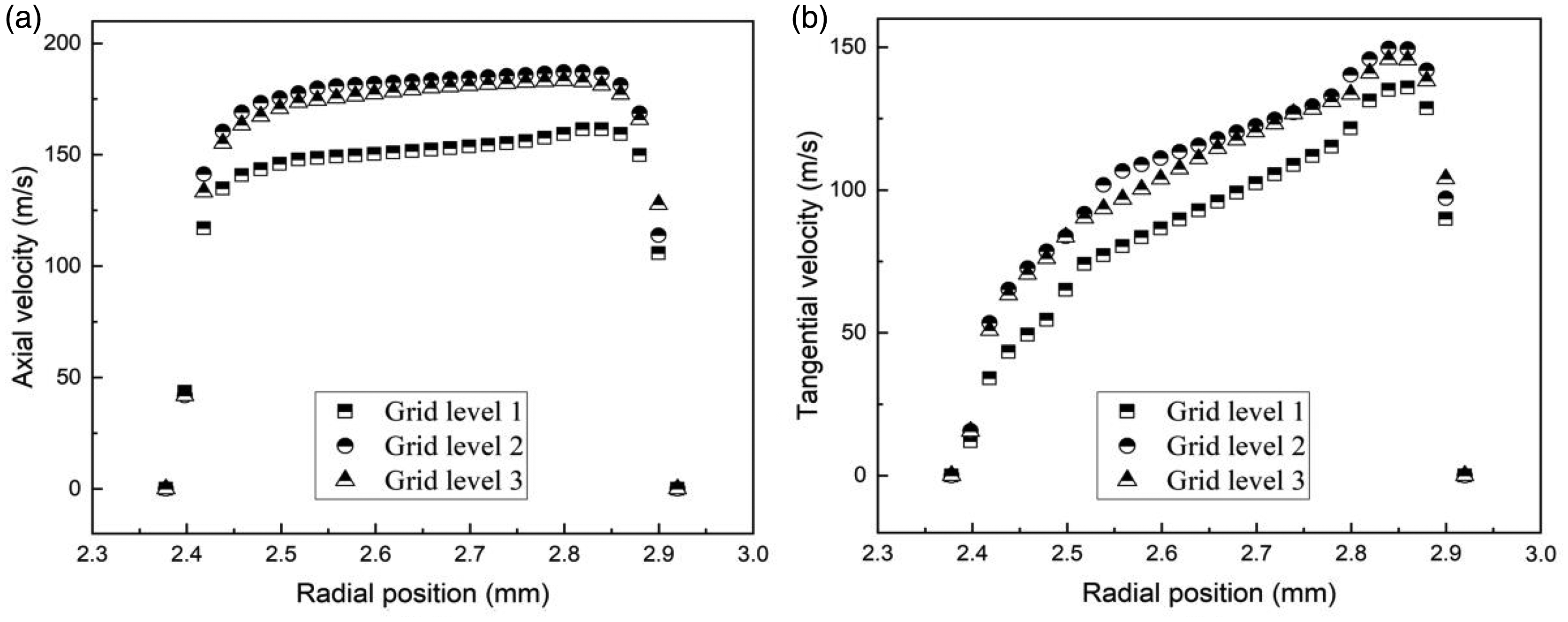
Radial distribution of the (a) axial and (b) tangential velocities at the monitoring surface for different grid levels in case 3.
Chang and Dhir 28 used an anemometer with a straight wire probe and a 45° slanted wire probe to measure the turbulent flow field in a tube with tangential injectors. The axial velocity obtained by this experiment is accurate to ±7% of the bulk axial velocity, while the tangential velocity is accurate to ±13% of the bulk axial velocity. To verify the numerical model adopted in this research, the case with a tangential to total momentum flux rate ratio of 7.84 is reproductively simulated using the numerical scheme presented above. The simulation results are then compared with the experimental data provided by Chang and Dhir. 28 Figure 5(a) and (b) shows the comparison between the numerical results and experimental data for the radial distribution of axial and tangential velocities at the axial position at seven tube diameters from the injector outlets, respectively. As can be seen, a good agreement between the simulated results and experimental data from Chang and Dhir 28 is found for the axial velocity. Although the simulated tangential velocity is consistent with the experimental data in the trend, there is a difference in the radial location of the maximum value. As some details of the experiment were not fully presented in the literature, the boundary conditions prescribed at the injector inlets may not be completely consistent with those employed in the experiment. This might be a cause for the discrepancy between the simulated profile and the measured data. In addition, it is reported that measurements could not be carried out at the position very close to the wall, thus the rapid decrease of velocity near the wall may not be able to be shown by the experimental data. According to the verification results, although the simulated velocity profiles based on the numerical scheme adopted in this study have shown some deviations from the experimental data, their accuracy is generally acceptable. Therefore, this numerical scheme is used for the simulation of the flow field inside the vortex spinning nozzle.
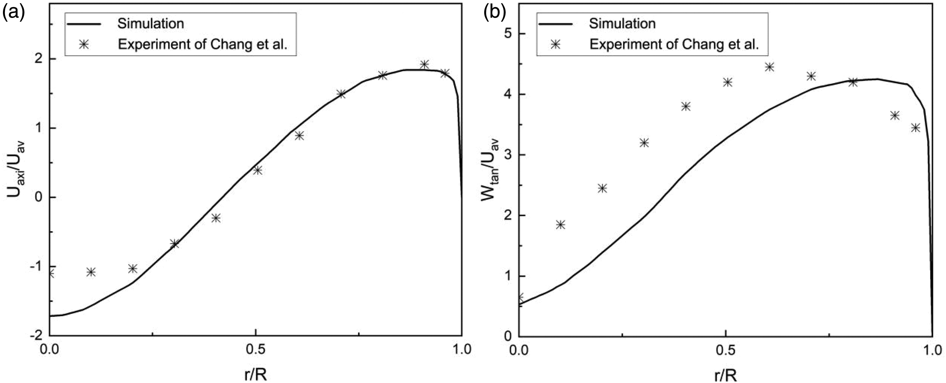
The data of numerical simulation and the experiments of Chang and Dhir 28 of the radial distribution of (a) axial and (b) tangential velocities at seven tube diameters from injector outlets.
Flow characteristics in the nozzle
In this section, the flow field inside the nozzle is investigated based on the results of the numerical simulation. Considering the significant impact of the flow characteristics on the yarn production process, attention is mainly paid to the static pressure and velocity of the airflow inside the nozzle. Figure 6(a) and (b) presents the static pressure contours in two orthogonal planes that pass through the Z-axis of the nozzle in case 3. It is evident that the static pressure of the airflow inside the nozzle is generally below the atmospheric pressure. In the annular region between the spindle and vortex tube, the value of static pressure in the region surrounding the spindle tip and the cross section with the minimum area is the lowest – that is, below 80,000 Pa. Figure 6(c) and (d) shows the streamlines and velocity contours in the planes of X = 0 mm and Y = 0 mm, respectively. It can be found that the airflow in the annular region between the spindle and vortex tube surrounding the spindle tip exhibits a maximum velocity that exceeds 500 m/s, which in turn results in a reduced static pressure. This is because the compressed air is injected toward the wall of the spindle tip through the tangential injectors. Due to the subpressure in the core region inside the nozzle, two streams of secondary flows with velocities below 200 m/s enter the vortex chamber through the three-dimensional spiral guiding passage and the yarn passage, respectively. The interaction between these secondary flows generates several vortices inside the vortex chamber due to the shear effects. Subsequently, these two secondary flows are then entrained into the high-speed swirling airflow formed by the air jets from the tangential injectors, as shown in Figure 6(e). Figure 7(a) to (f) presents the velocity vectors and velocity magnitude contours in different cross-sections of the nozzle. In the plane of the spiral guiding passage exit (Z = 7.03 mm) and the plane of 2 mm downstream of the spiral guiding passage exit (Z = 9.03 mm), as shown in Figure 7(a) and (b), the irregular behavior of velocity distribution in the vortex chamber can be observed due to the generation of vortices. Notably, at the cross-section where the spindle inlet plane locates, as illustrated in Figure 7(c), there is a tendency for swirling airflow generation due to the expansion of airflow near the injector exits. The secondary flows are entrained by the air jet, turning to a swirling motion around the spindle. These air streams move downstream around the positive Z-axis, gradually generating a stable swirling flow, which can be seen in the plane of 1 mm (Z = 11.9 mm), 2 mm (Z = 12.9 mm), and 5 mm (Z = 15.9 mm) downstream of the spindle inlet plane, as shown in Figure 7(d) to (f).

Static pressure contours in the planes of (a) X = 0 mm and (b) Y = 0 mm, streamline and velocity contours in the planes of (c) X = 0 mm and (d) Y = 0 mm, and (e) three-dimensional streamline diagram of airflow in the nozzle.
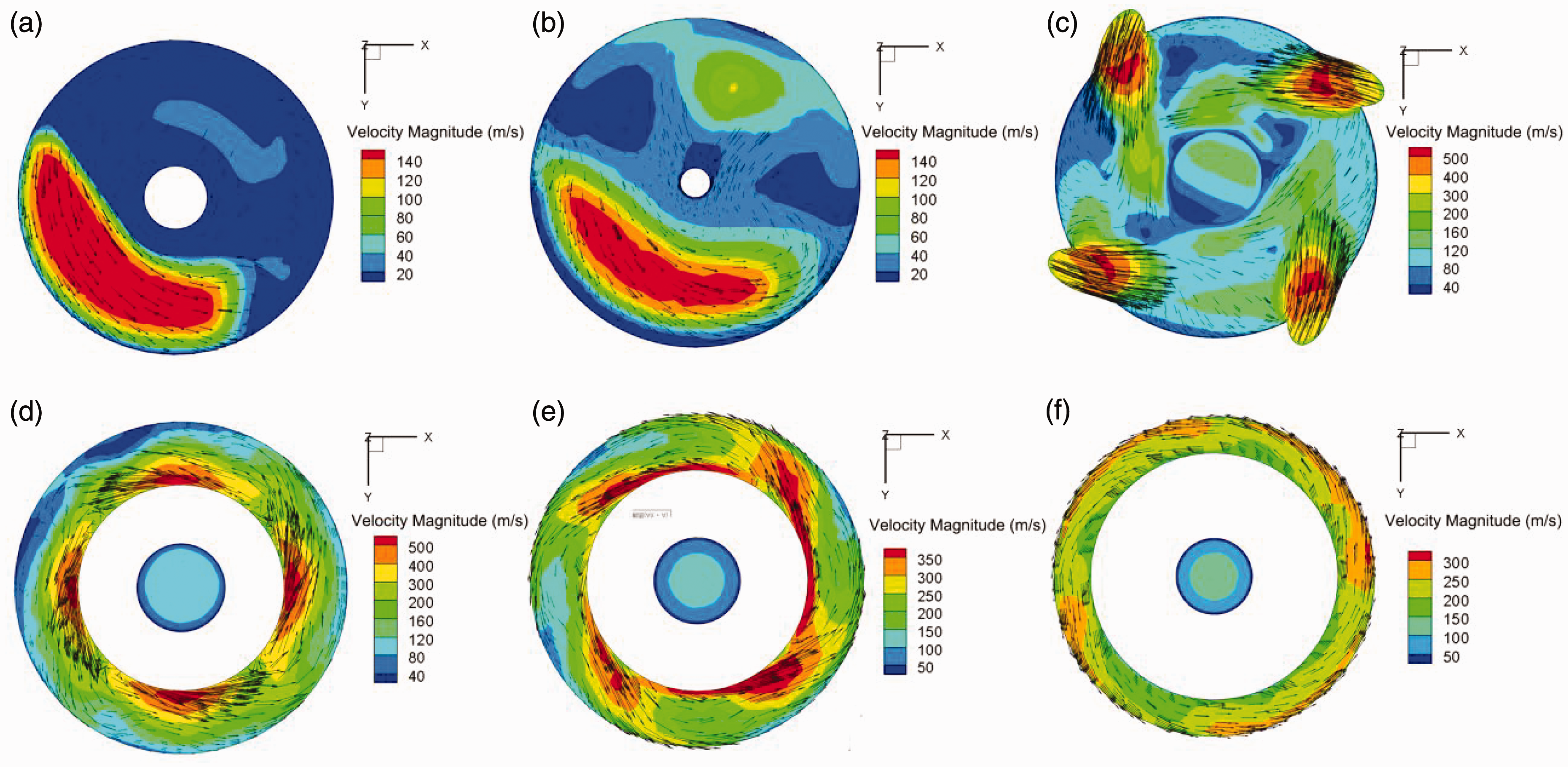
Velocity vectors and velocity magnitude contours in different cross-sections of the nozzle: (a) Z = 7.03 mm; (b) Z = 9.03 mm; (c) Z = 10.9 mm; (d) Z = 11.9 mm; (e) Z = 12.9 mm and (f) Z = 15.9 mm.
Considering the importance of the airflow velocity in the annular region between the vortex tube and the spindle in the twist insertion, the velocity characteristics of airflow in this region are studied. In particular, the tangential and axial velocities in the plane of the spindle inlet, as well as in the planes of 1 mm, 2 mm, 3 mm, and 5 mm downstream of the spindle inlet are analyzed. Figure 8(a) illustrates the radial distribution of tangential velocity in different cross-sections in the plane of X = 0 mm. The positive tangential velocity is in the anticlockwise direction when observed along the positive Z-axis. The tangential velocity exhibits negative values in the plane of the spindle inlet (Z = 10.9 mm) near the wall of the vortex tube, which is due to the influence of vortices in the vortex chamber. With the increase of the radial distance, the tangential velocity in the plane of Z = 11.9 mm first shows a sharp increasing trend from the spindle wall followed by a decrease along the radial direction, with the value of tangential velocity dropping to zero at the vortex tube wall. In the planes of Z = 13.9 mm and Z = 15.9 mm, with the increase of radial distance from the spindle wall, the tangential velocity also first increases rapidly near the spindle wall. Then the increasing trend becomes moderate, while the tangential velocity decreases to zero sharply near the vortex tube wall. It can also be observed that the maximum value of the tangential velocity is located near the spindle wall in the plane of Z = 11.9 mm, whereas the maximum values in the planes of Z = 13.9 mm and Z = 15.9 mm are gradually shifted toward the vortex tube wall. The maximum value of tangential velocity in different cross-sections is the highest in the plane of Z = 11.9 mm, which results in a high efficiency of twist insertion. At the cross-section of Z = 12.9 mm, two peaks are observed on the tangential velocity curve. The reason for this phenomenon is that the air jets from the injectors sweep past the spindle wall at the position of Z = 11.9 mm and collide with the vortex tube wall in the plane of Z = 12.9 mm. Figure 8(b) illustrates the radial distribution of axial velocities in different cross-sections in the plane of X = 0 mm. Due to the influence of secondary flow in the yarn passage, the axial velocity with a negative value can be observed in the plane of the spindle inlet (Z = 10.9 mm). It can also be observed that the maximum value is obtained at the cross-section of Z = 11.9 mm in the annular region between the vortex tube and the spindle. This is advantageous for the fiber to expand on the spindle tip to improve the twisting efficiency of fibers. In addition, a decrease in both axial and tangential velocities can be observed from the plane of Z = 11.9 mm downstream to the plane of Z = 15.9 mm. The decay of the swirling flow inside a tube has been reported previously by experimental and simulation studies. 29 The mechanism behind the velocity attenuation is that the kinetic energy is converted into other forms of energy. This leads to the change of the energy in the airflow in the annular region between the vortex tube and the spindle.
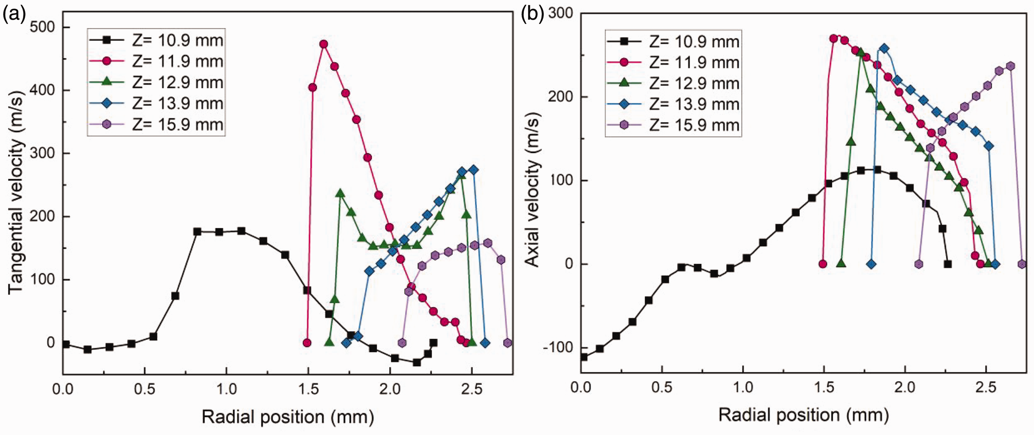
Radial distribution of the tangential and axial velocities in different cross-sections of the annular area between the vortex tube and the spindle in the planes of X = 0 mm.
Effects of nozzle structural parameters on air consumption
The length of the conical chamber in the intermediate section of the vortex tube
Figure 9(a) shows the static pressure contours inside the nozzle with different lengths (L) of the conical chamber in the intermediate section of the vortex tube. Different pressure characteristics can be seen for the nozzles under investigation. For the conical chamber with a length of L = 7.3 mm, L = 7.5 mm, and L = 7.7 mm, the static pressure in the nozzle is insignificantly affected. For the conical chamber with a length of L = 7.9 mm and L = 8.1 mm, an increase in the static pressure value can be observed compared with the other three cases, while the static pressure in the case with L = 8.1 mm is even higher than the case with L = 7.9 mm. This must have resulted from the change in the minimum cross-sectional area in the annular region between the vortex tube and the spindle as a result of the change of L. The cross-section with the minimum area locates at the axial position where the two conical chambers in the vortex tube are connected. As the cone angle of the spindle is larger than that of the conical chamber in the intermediate section of the vortex tube, the axial position of the cross-section with the minimum area moves downstream with its area being decreased with the increase in the length of the conical chamber. A smaller minimum cross-sectional area can result in a more significant suppression of the airflow being exhausted from the nozzle, leading to higher static pressure values in the nozzle. For the cases of L = 7.3 mm, 7.5 mm, and 7.7 mm, the cross-section with the minimum area lies in the annular region between the vortex tube and the first cone of the spindle. As a result, the variation of L in the three cases leads to a gentle change of the minimum cross-sectional area, and in turn an insignificant change of the static pressure in the nozzle. In comparison, for the cases of L = 7.9 mm and 8.1 mm, the axial position of the cross-section with the minimum area lies in the annular region between the vortex tube and the second cone of the spindle. As the angle of the second cone of the spindle is higher than that of the first cone, the minimum cross-sectional area is further decreased compared with the previous three cases, while the minimum cross-sectional area is even smaller for the case of L = 8.1 mm than that in the case of L = 7.9 mm. Figure 9(b) shows the kinetic energy contours inside the nozzles with different lengths of the conical chamber in the intermediate section of the vortex tube. It can be observed that the kinetic energy of the airflow in the position a short distance downstream of the spindle inlet exhibits a small difference among the cases of L = 7.3 mm, 7.5 mm, and 7.7 mm. For the cases of L = 7.9 mm and 8.1 mm, the decrease in kinetic energy of the airflow in the position a short distance downstream of the spindle inlet can also be observed, indicating that the dependence of kinetic energy on L shows an inverse trend to the static pressure. Figure 10 presents the velocity magnitude contours in the cross-section at the injector exits. It can be observed that there is a small difference in velocity in the vicinity of the injector exits for the cases of L = 7.3 mm, 7.5 mm, and 7.7 mm. Compared with these three cases, there is a significant reduction of the area where the velocity near the injector exits exceeds 500 m/s in the cases of L = 7.9 mm and 8.1 mm, while the reduction in the case of L = 8.1 mm is even more pronounced than that in the case of L = 7.9 mm. The pressure difference between the air reservoir and the nozzle chamber is the main driving force for the swirling flow inside the nozzle. A lower driving force results in a decreased airflow velocity at the injector exits. This leads to less compressed air entering the nozzle per unit time, which results in the reduction of air consumption. Therefore, the highest static pressure inside the nozzle as well as the smallest pressure difference between the air reservoir and the nozzle chamber can be obtained in the case of L = 8.1 mm, which can lead to the lowest flow rate and air consumption for the nozzle.
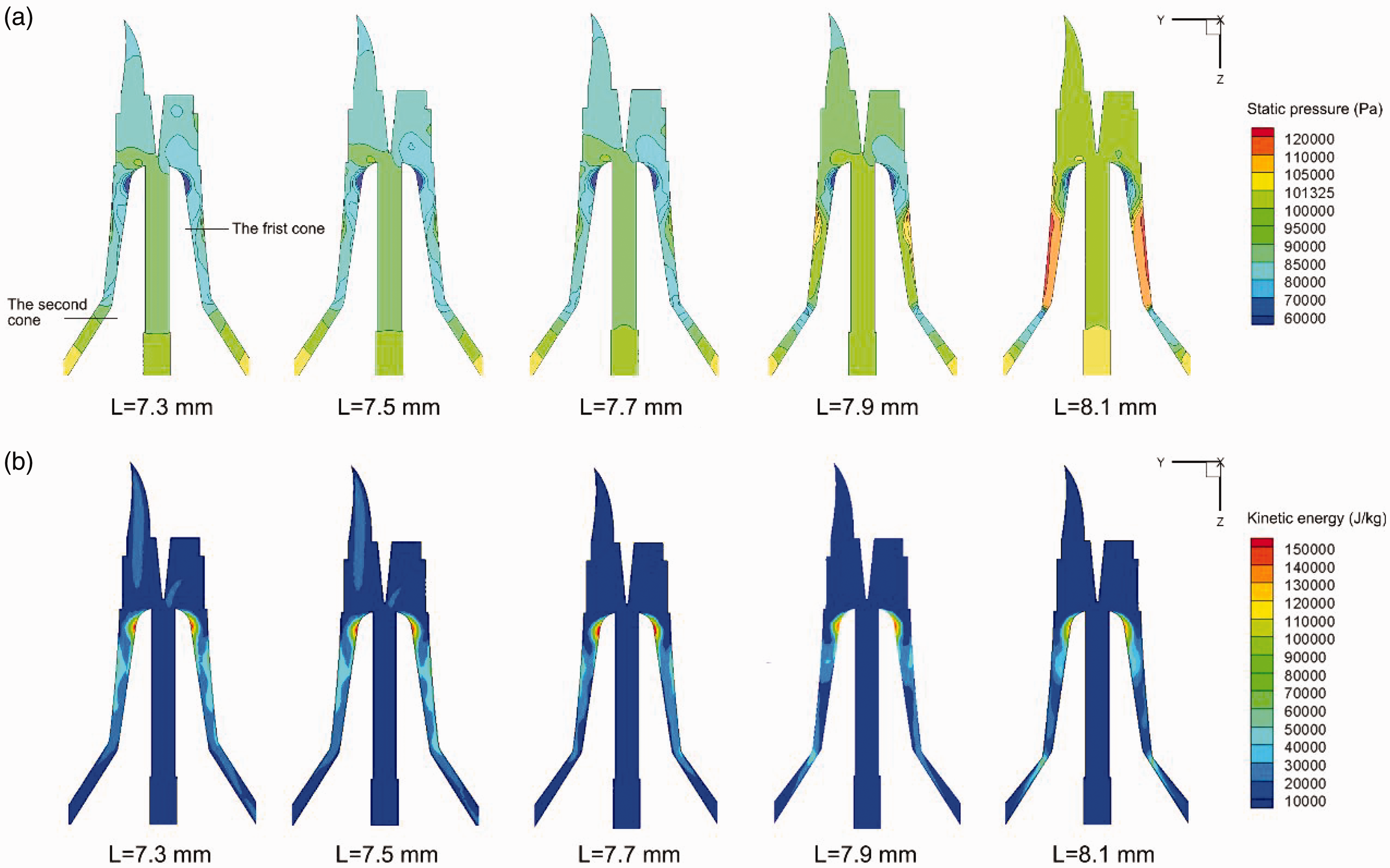
(a) The static pressure and (b) kinetic energy contours in the plane of X = 0 mm of the nozzle with different lengths of the conical chamber.

The velocity magnitude contours in the cross-section at the injector exits (Z = 11.9 mm) of the nozzle with different lengths of conical chamber.
Inlet diameter of the conical chamber in the intermediate section of the vortex tube
Figure 11(a) illustrates the static pressure contours inside the nozzle with different inlet diameters (D) of the conical chamber in the intermediate section of the vortex tube. It can be observed that the static pressure inside the nozzle increases as D decreases. This results from the decrease in the volume of the annular region as well as the minimum cross-sectional area between the vortex tube and the spindle. The change in the volume of the annular region results in different sizes of flow region for the swirling airflow. The decreased volume of the annular region and minimum cross-sectional area led by a smaller D prevents the airflow from being discharged out of the nozzle, resulting in the increase of the static pressure. Figure 11(b) shows the contours of kinetic energy of the airflow in the nozzle for the cases with different D values. It can be observed that the kinetic energy in the region a short distance downstream of the spindle inlet exhibits a small difference as D varies. This is because although the pressure difference between the air reservoir and the nozzle chamber increases as D increases, the increased volume inside the nozzle inhibits the increase of airflow velocity. In addition, it can also be observed that as D decreases, the kinetic energy in the cross-section with the minimum area increases. This indicates that reducing the minimum cross-sectional area can effectively suppress the decay of swirling airflow inside the nozzle, which can help increase the efficiency of twist insertion into the fiber strand. Figure 12 presents the velocity magnitude contours in the cross-section at the injector exits. It can be observed that as D increases, the area in which the velocity of air jets from the injectors exceeds 500 m/s expands. This also indicates that a larger pressure difference between the air reservoir and the nozzle chamber can lead to the higher velocity of the air jets. In general, the velocity of the air jets from the injectors is lower for nozzles with a smaller inlet diameter of the conical chamber, resulting in the reduction of air consumption. Therefore, the nozzle with the smaller inlet diameter of the conical chamber is more energy efficient.
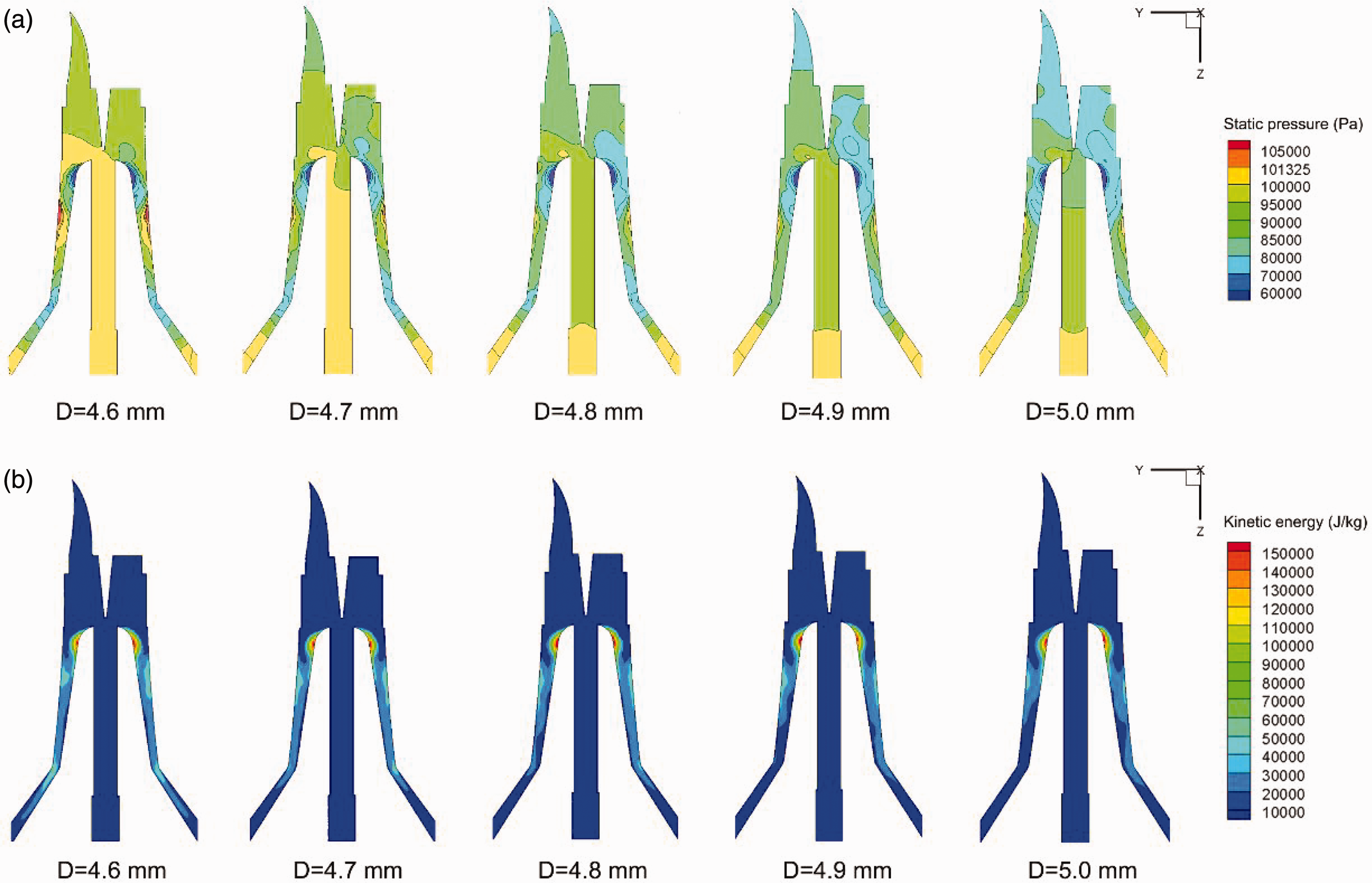
(a) The static pressure and (b) kinetic energy contours in the plane of X = 0 mm of the nozzle with different inlet diameters of the conical chamber.
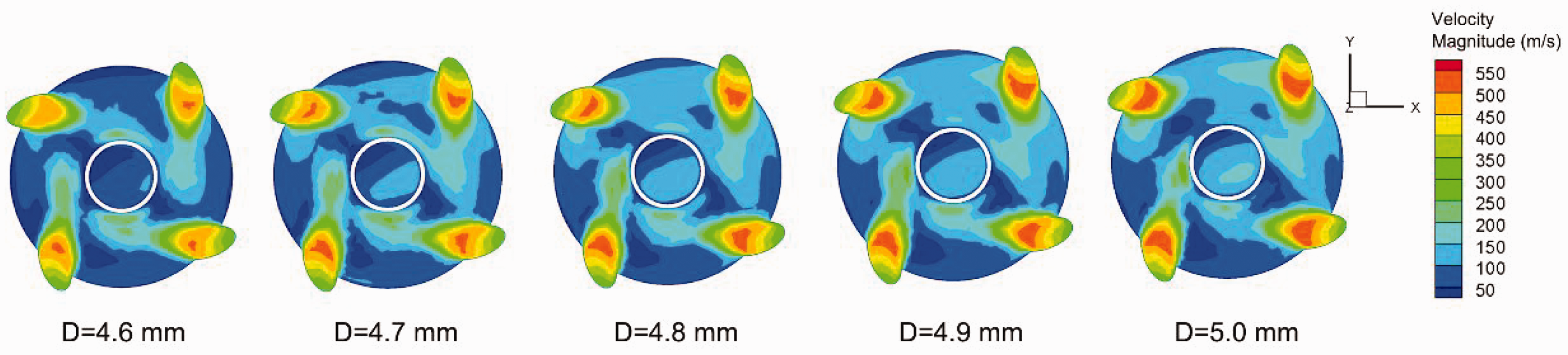
The velocity magnitude contours in the cross-section at the injector exits (Z = 11.9 mm) of the nozzle with different inlet diameters of the conical chamber.
Effects of nozzle structural parameters on mechanical energy characteristics
In the process of vortex spinning, fibers are separated inside the vortex chamber and are twisted in the annular region between the vortex tube and the spindle. Excessive or insufficient mechanical energy of the airflow inside the nozzle can affect both the efficiency of fiber separation and twist insertion, thereby affecting the yarn property. In addition, the mechanical energy characteristics are closely related to the energy loss during the spinning process. Therefore, the effects of the length and inlet diameter of the conical chamber in the intermediate section of the vortex tube on the mechanical energy characteristics of the airflow inside the nozzles are studied based on the simulation results in this section.
The length of the conical chamber in the intermediate section of the vortex tube
The mechanical energy of fluid includes the kinetic energy, pressure energy and potential energy.
30
Considering the slight change of the fluid position inside the nozzle, the potential energy can be ignored. Thus, the mechanical energy can be written as

To obtain the mechanical energy characteristics along the flow direction, the average mechanical energy of the airflow in different cross-sections at 1 mm intervals along the positive Z direction for the nozzles with different conical chamber lengths (L) is calculated, as shown in Figure 13. According to the characteristics of the mechanical energy, the curves are divided into three zones – zone I, zone II, and zone III. It can be observed that the mechanical energy characteristics are significantly affected by the conical chamber lengths. In zone I, which refers to the fluid domain between the nozzle inlet and 3 mm downstream of the spiral guiding passage exit, there is a gradual decrease followed by a gradual increase for mechanical energy. As the length of the conical chamber increases, the mechanical energy in zone I exhibits a notable decrease, which is particularly pronounced at the lengths of 7.9 mm and 8.1 mm. This is related to the magnitude of the difference of pressure of the airflow in the inlet of the guiding passage and the nozzle chamber. The fiber separation taking place in this region determines the number of wrapper fibers, and in turn exerts a significant influence on the yarn strength. The reduced mechanical energy of airflow in this region can result in a decreased airflow velocity, which adversely affects the efficiency of fiber separation. However, excessively high mechanical energy in this region can not only lead to excessive separation of fibers, but will also lead to the extremely high tangential and axial velocity components, which in turn results in the increase of wasted fibers during the spinning process. This is not beneficial for the production of high-quality yarn. To obtain the details of energy characteristics in this region, the radial distribution of mechanical energy at the exit (Z = 7.03 mm), 1 mm (Z = 8.03 mm), and 2 mm (Z = 9.03 mm) downstream of the spiral guiding passage exit are analyzed, as shown in Figure 14(a), (b) and (c), respectively. Minor discrepancy for the mechanical energy can be observed for the conical chambers with a length of 7.3 mm and 7.5 mm, while the length of 7.7 mm leads to a slightly decreased mechanical energy in this region. For the conical chambers with L = 7.9 mm and L = 8.1 mm, the mechanical energy of the airflow in this region is significantly decreased, which results in a low fiber separation efficiency. In zone II, which refers to the fluid domain from the position 3 mm downstream of the spiral guiding passage exit to the position 1 mm downstream of the spindle inlet, a rapid increase followed by a gentle increase of the mechanical energy can be observed, which results from the air jets from the injectors. Figure 14(d) presents the radial distribution of mechanical energy in the cross-section located at 1 mm downstream of the spindle inlet (Z = 11.9 mm) in zone II where the mechanical energy characteristics have a significant impact on the twist insertion into the fibers. Minor discrepancies for the mechanical energy among the cases of L = 7.3 mm, L = 7.5 mm, and L = 7.7 mm can be observed, while in the cases of L = 7.9 mm and L = 8.1 mm, the mechanical energy is further decreased. This results from the magnitude of the pressure difference between the inlet of the air reservoir and the nozzle chamber. However, the decrease in mechanical energy in this region can lead to the decrease of the tangential velocity of the airflow, which results in the lowered twisting efficiency of fibers. In zone III, which refers to the fluid domain from 1 mm to 7 mm downstream of the spindle inlet as the position moves to the downstream, a decreasing trend for the mechanical energy of the airflow in all the cases can obviously be observed. Figure 14(e) and (f) presents the radial distribution of mechanical energy in the cross-sections at 4 mm (Z = 14.9 mm) and 7 mm (Z = 17.9 mm) downstream of the spindle inlet, respectively. For the cases of L = 7.3 mm, L = 7.5 mm, and L = 7.7 mm, little difference of the mechanical energy of the airflow has been observed. In comparison, for the cases of L = 7.9 mm and L = 8.1 mm, the mechanical energy significantly decreases in the region next to the wall of the vortex tube, which also has a detrimental effect on the twist insertion process. In addition, it can be observed that the mechanical energy exhibits a greater decrease in zone III for the cases of L = 7.9 mm and L = 8.1 mm. This is due to the decrease in the area of the minimum cross-section, which suppresses the discharge of airflow from the nozzle. As a result, the viscous friction between fluid layers as well as the friction between the fluid and the wall surface will be increased, thus leading to more mechanical energy being converted into heat. Moreover, a smaller minimum cross-sectional area can lead to a higher local pressure drop near the minimum cross-sectional area, as shown in Figure 9, which also increases the loss of mechanical energy. In summary, the mechanical energy of airflow inside the nozzle in the cases of L = 7.9 mm and L = 8.1 mm is significantly decreased compared with the cases of L = 7.3 mm, L = 7.5 mm, and L = 7.7 mm in which the mechanical energy is similar. As a result, for the cases of L = 7.3 mm, L = 7.5 mm, and L = 7.7 mm, minor differences in yarn strength can be predicted due to the insignificant difference in the efficiency of fiber separation and twist insertion, while for the cases of L = 7.9 mm and L = 8.1 mm, the yarn strength may decrease significantly due to the lower efficiency of fiber separation and twist insertion.
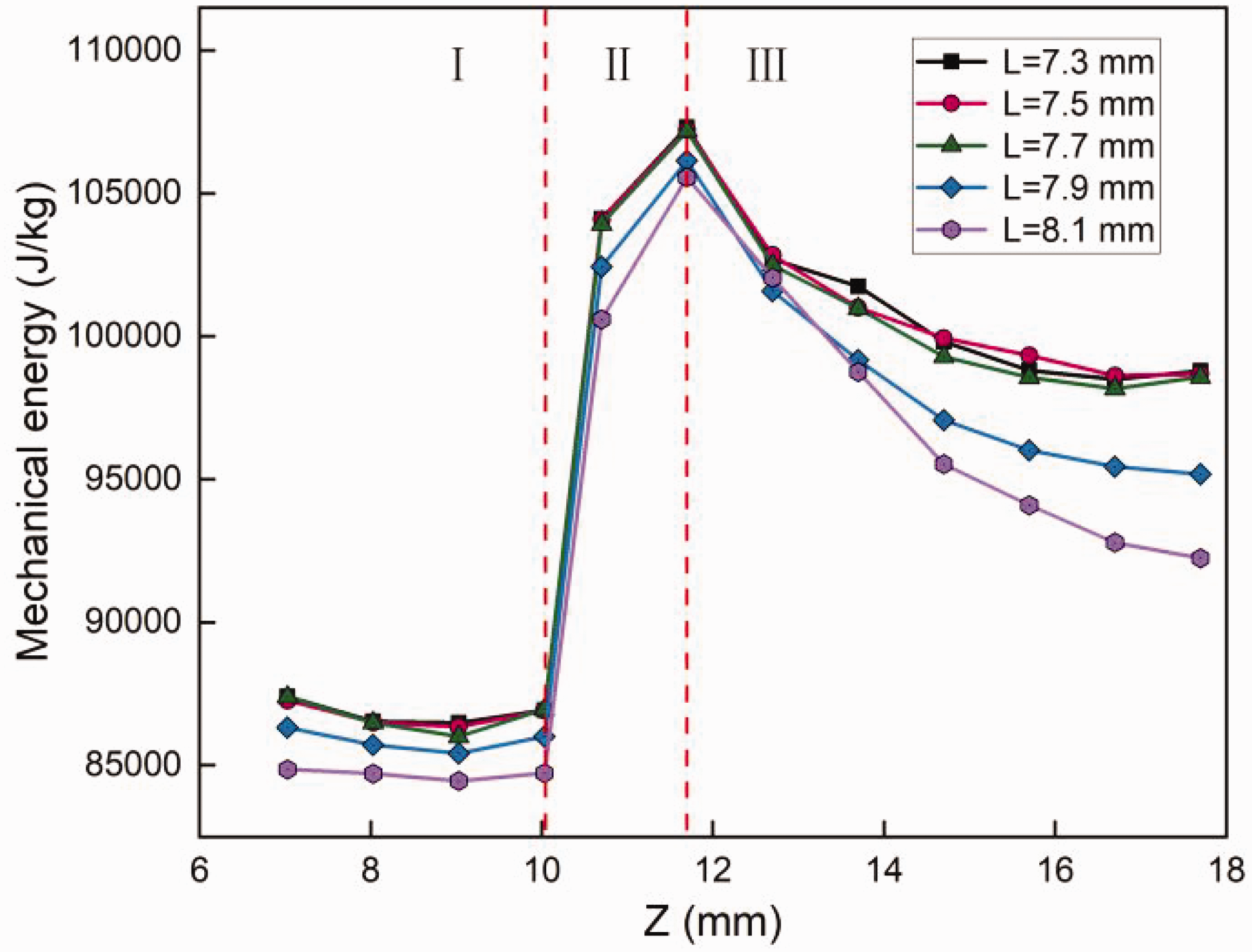
The average mechanical energy of the airflow in different cross-sections along the Z-axis in the nozzles with different conical chamber lengths.
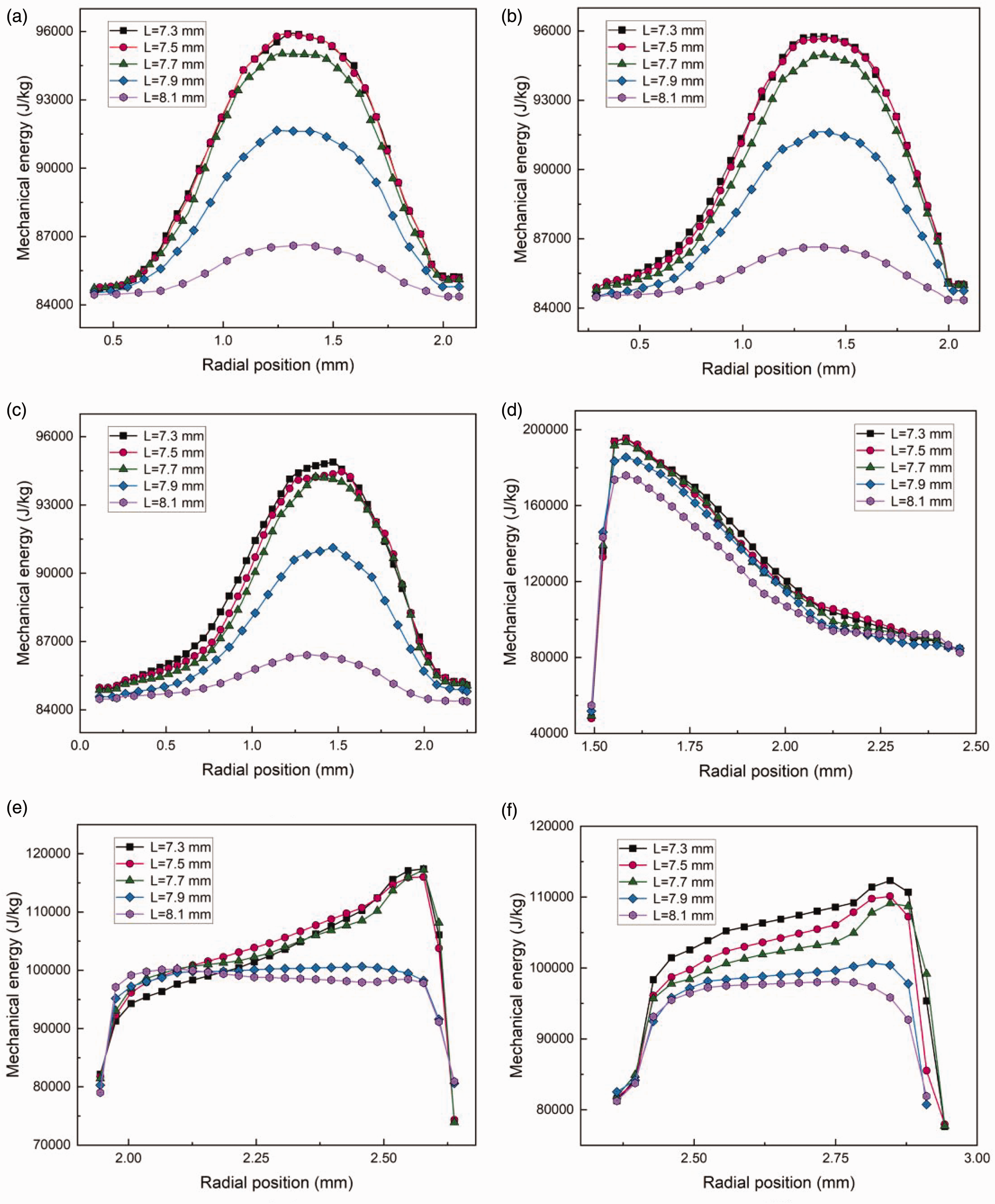
Radial distribution of mechanical energy in the nozzles with different conical chamber lengths in the plane of X = 0 mm: (a) Z = 7.03 mm; (b) Z = 8.03 mm; (c) Z = 9.03 mm; (d) Z = 11.9 mm; (e) Z = 14.9 mm and (f) Z = 17.9 mm.
The inlet diameter of the conical chamber in the intermediate section of the vortex tube
Figure 15 presents the average mechanical energy of the airflow in different cross-sections along the positive Z direction in the nozzles with different conical chamber inlet diameters (D). It can be seen that the mechanical energy shows an increasing trend in zone I as the inlet diameter of the conical chamber increases. Figure 16(a), (b) and (c) displays the radial distribution of mechanical energy at the exit (Z = 7.03 mm), 1 mm (Z = 8.03 mm), and 2 mm (Z = 9.03 mm) downstream of the spiral guiding passage under different inlet diameters of the conical chamber, respectively. A noticeable increase of the mechanical energy of airflow in this region can be observed with the increase in the inlet diameter of the conical chamber, which will lead to the excessive separation of fibers. In the upstream region of zone II, the mechanical energy of airflow increases rapidly as the position moves downstream, while a similar effect of the inlet diameter on the mechanical energy to zone I is shown. Different from the upstream region, the increasing rate of the mechanical energy decreases in the midstream region of zone II, while the inverse relationship between the mechanical energy and the inlet diameter can be observed in the downstream region of this zone. The higher mechanical energy in the upstream and midstream of zone II at larger inlet diameters can be observed, as shown in Figure 11. Figure 16(d) presents the radial distribution of mechanical energy in the cross-section located at 1 mm downstream of the spindle inlet (Z = 11.9 mm) in the downstream region of zone II. It can be observed that as the inlet diameter increases, the mechanical energy slightly decreases, which will in turn result in lower twist-insertion efficiency. This characteristic of mechanical energy can be attributed to the reduced airflow velocity due to the enlarged flow area as a result of the enlarged annular region between the spindle and the vortex tube in the cases of larger inlet diameters, as shown in Figure 12. Figure 16(e) and (f) presents the radial distribution of mechanical energy of airflow in the cross-sections located at 4 mm (Z = 14.9 mm) and 7 mm (Z = 17.9 mm) downstream of the spindle inlet, which is located in the midstream and downstream of zone III, respectively. As shown in Figure 15 and Figure 16(e) and (f), the mechanical energy of airflow decreases as the inlet diameter increases in the upstream and downstream of zone III, while a significant decrease of the mechanical energy can be observed for the case of D = 4.6 in the midstream region of zone III. This indicates that in the case of D = 4.6 mm, a greater portion of the mechanical energy is converted to other types of energy in the midstream of zone III, which will negatively impact the yarn production process. In addition, it can be observed from Figure 15 that there is an increasing trend of the mechanical energy as the position moves downstream in the cases of D = 4.6 mm, D = 4.7 mm, and D = 4.8 mm in the downstream region of zone III. This results from the higher airflow velocity led by the smaller minimum cross-sectional area between the vortex tube and the spindle. As can be seen, the mechanical energy of the airflow inside the vortex chamber increases with the increase of the conical chamber inlet diameter, while that in the annular region between the vortex tube and the spindle decreases except for the case of L = 4.6 mm. As a result, it can be predicted that the twisting efficiency of fibers decreases with the increase of the conical chamber inlet diameter except in the case of D = 4.6 mm. In addition, it has been found that neither excessively small nor large inlet diameters are conducive to fiber separation. Therefore, the yarn strength will first increase and then decrease with the increase of the inlet diameter of the conical chamber.
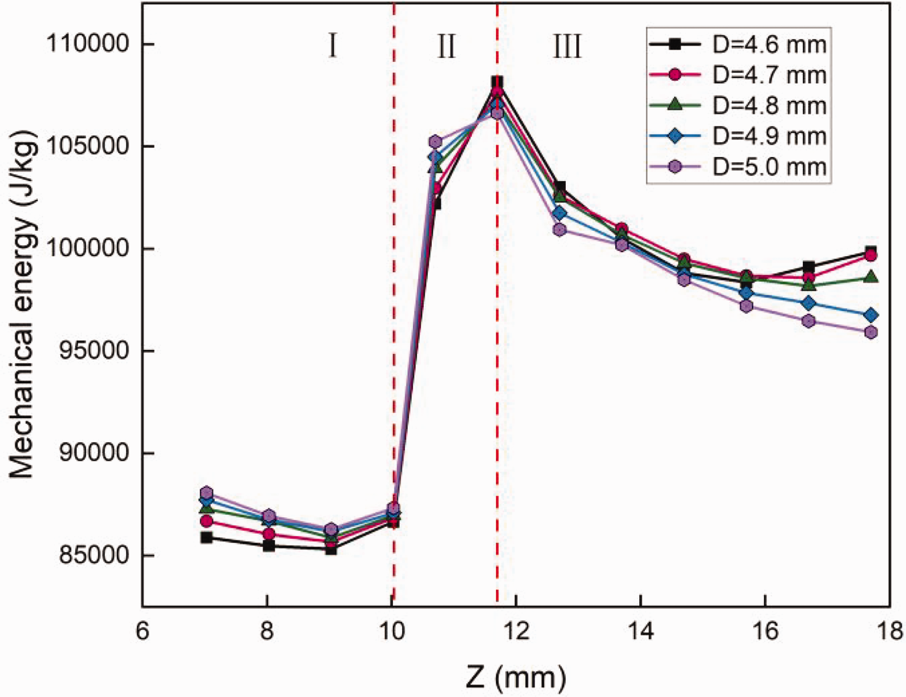
The average mechanical energy of the airflow in different cross-sections along the Z-axis in the nozzles with different conical chamber inlet diameters.
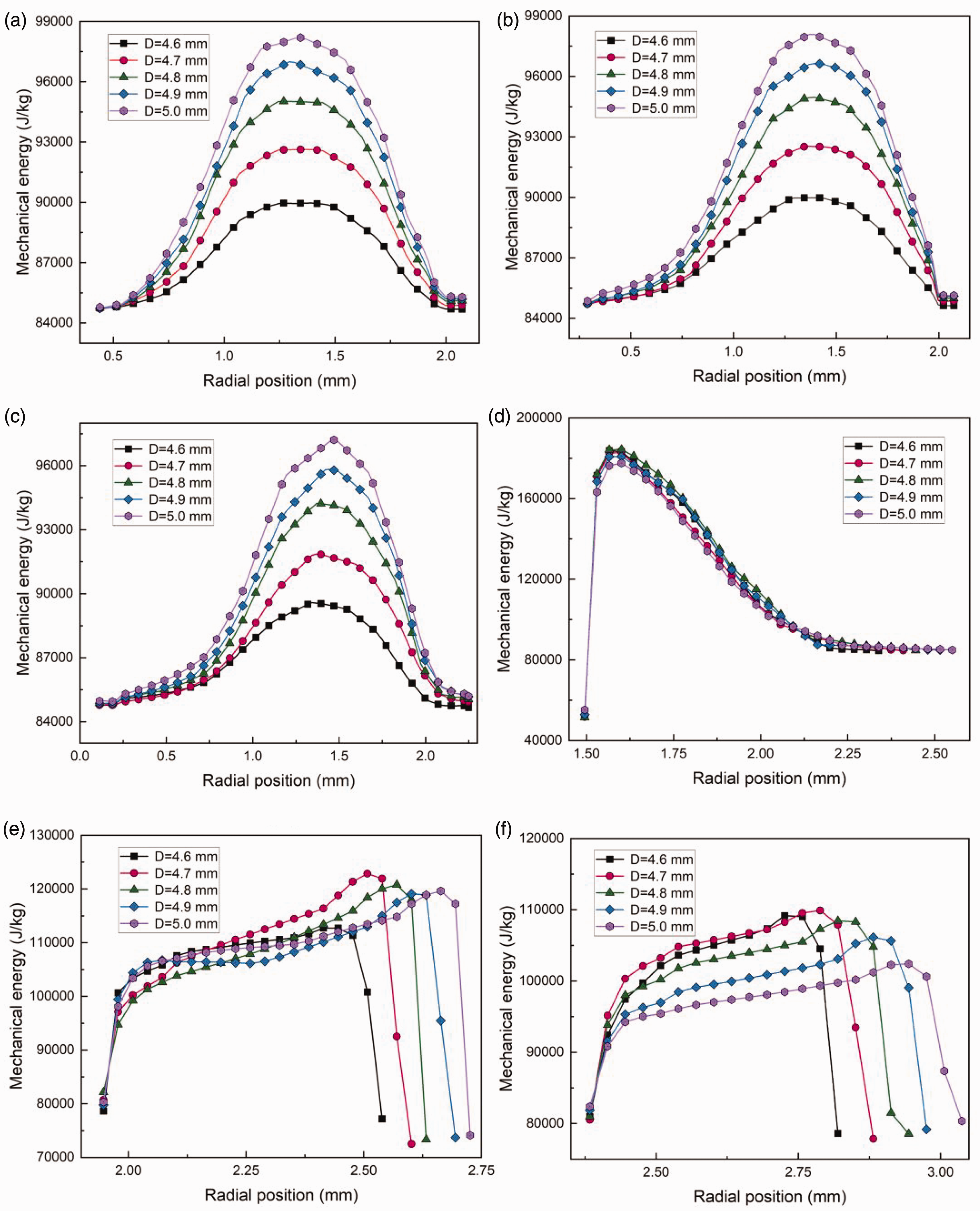
Radial distribution of mechanical energy in the nozzles with different conical chamber inlet diameters in the plane of X = 0 mm: (a) Z = 7.03 mm; (b) Z = 8.03 mm; (c) Z = 9.03 mm; (d) Z = 11.9 mm; (e) Z = 14.9 mm and (f) Z = 17.9 mm.
Spinning experiment
To verify the results of the effects of nozzle structural parameters on the yarn performance obtained based on the numerical simulation, a spinning experiment of vortex yarns is conducted on a vortex spintester (model DHU-P02). Viscose rayon staple fibers with a mean length of 38 mm and a fineness of 1.5 dtex are selected as the material for the experiments. The staple fibers are converted into rovings with a linear density of 680 tex, and are then fed into the spintester to produce vortex yarns with a designed linear density of 21 tex. The main process parameters are listed in Table 2. A rotor flowmeter (LZB-10WB; Yuyao Qiquan Flux Instrument Co., Ltd., China) is attached to the air supply tube connecting the air source and the air reservoir of the nozzle to measure the flow rate of the airflow entering the nozzle from the air reservoir. Yarn breaking tenacity is tested on the yarn tensile tester (YG061-1500; Laizhou Electronic Instrument Co., Ltd., China) according to ASTM standard D2256. In addition, the flow rate of the nozzle equipped with an industrially used vortex tube and the strength of the yarn spun with this nozzle are both measured for comparison.
Main process parameters for spinning experiment

Figure 17(a) shows experimental result of the effect of the length of the conical chamber in the intermediate section (L) on the flow rate of the airflow entering the nozzle from the air reservoir during the spinning process. It can be found that the air flow rate decreases monotonically as L increases. The flow rate exhibits a slight decrease as L increases from 7.3 mm to 7.7 mm, while the decreasing trend becomes significant as L increases from 7.7 mm to 8.1 mm. Therefore, the air consumption during spinning reaches its minimum value at L = 8.1 mm, which is 17.62 L/min. This indicates a decrease of 5.5 L/min compared with the industrial condition. Figure 17(b) shows the effect of the inlet diameter of the conical chamber in the intermediate section (D) on the flow rate of the airflow entering the nozzle from the air reservoir during the spinning process. It can be observed that the flow rate increases significantly as D increases. The flow rate reaches its minimum value of 17.72 L/min in the case of D = 4.6 mm, which is decreased by 5.4 L/min compared with the industrial condition. As can be seen, the experimental results of the dependence of the flow rate on the nozzle structural parameters are consistent with the numerical simulation results of the air consumption. This has verified that the static pressure characteristics of the airflow in the nozzle play an important role in the air consumption. Figure 17(c) shows the experimental result of the effect of the length of the conical chamber in the intermediate section (L) on the yarn breaking tenacity. The yarn tenacity first increases slightly as L increases from 7.3 mm to 7.5 mm, and then exhibits a decreasing trend as L further increases from 7.5 mm to 8.1 mm. It can also be found that the yarn tenacities in the cases of L = 7.9 mm and L = 8.1 mm are both lower than those in the cases of L = 7.3 mm, L = 7.5 mm, and L = 7.7 mm. Figure 17(d) shows the experimental result of the effect of the inlet diameter of the conical chamber in the intermediate section (D) on the yarn breaking tenacity. The yarn tenacity first increases and then decreases with the increase of D, while the highest yarn tenacity is obtained at D = 4.8 mm. Therefore, the prediction of the dependence of the yarn tenacity on D based on the numerical simulation of the mechanical energy characteristics of the airflow is consistent with the experimental result. In addition, the yarn produced by the nozzle with reduced air consumption exhibits an acceptable tenacity compared with the tenacity of yarn produced under industrial conditions, which is 10.05 cN/tex. Based on the comparison of the numerical and experimental results, the feasibility of predicting the air consumption and yarn performance as well as designing the nozzle structural parameters based on the flow characteristics in the nozzle can be proved.
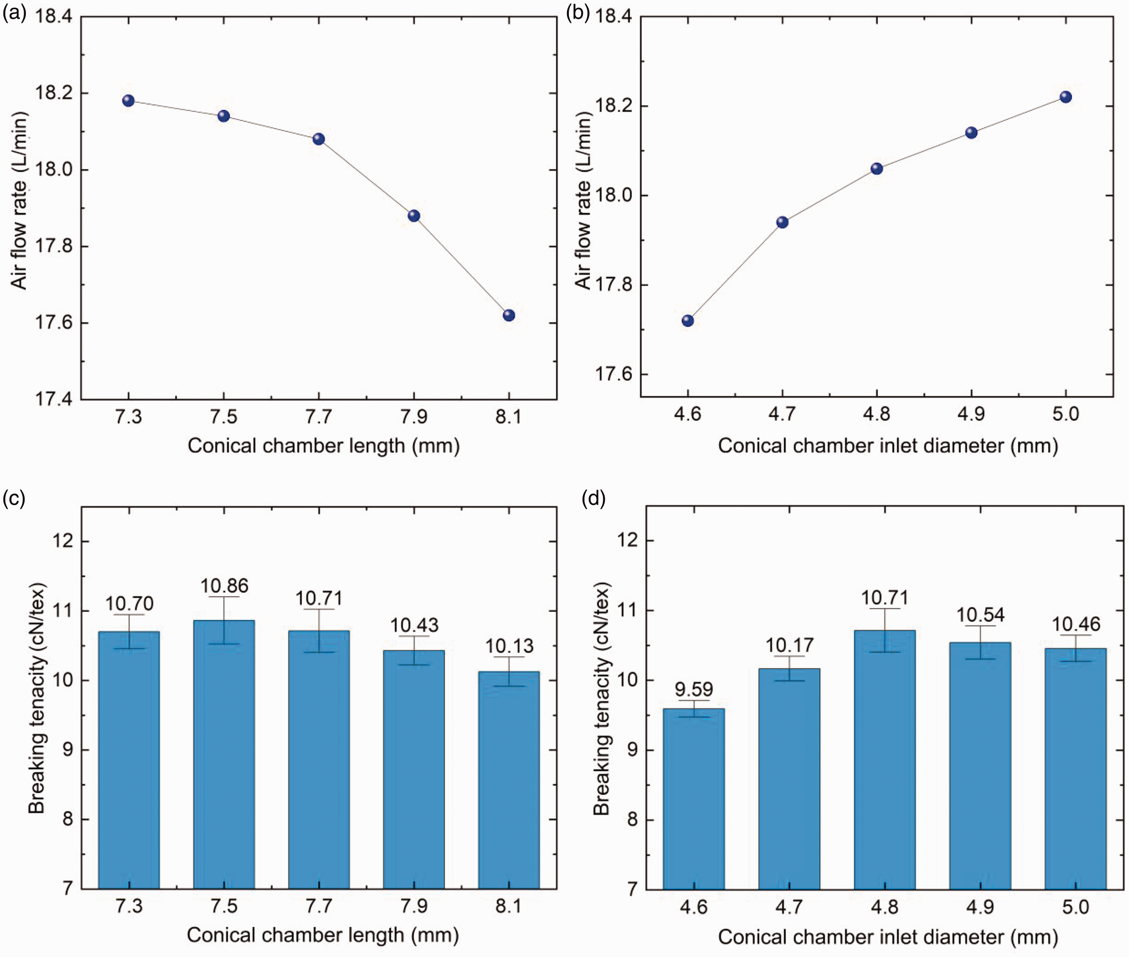
Experimental results of the effects of nozzle structural parameters of the conical chamber on (a) and (b) the air flow rate; and (c) and (d) the yarn breaking tenacity.
Conclusions
In this paper, the effects of the length (L) and inlet diameter (D) of the conical chamber in the intermediate section of the vortex tube on the air consumption and mechanical energy characteristics of the airflow in the nozzle of the vortex spinning machine are studied using three-dimensional CFD analysis. The flow rate of the air entering the nozzle from the air reservoir and the tenacity of vortex spun yarn are experimentally measured to verify the numerical simulation results. The following conclusions can be drawn:
The static pressure of the airflow in the region surrounding the spindle tip and the cross-section with the minimum area inside the nozzle reaches its minimum value. The maximum values of tangential and axial velocities of the airflow are both the highest in the plane 1 mm downstream of the spindle inlet. The flow velocities in the annular region between the vortex tube and the spindle exhibit a decaying trend toward downstream because of the variation of the mechanical energy. The static pressure of airflow is insignificantly affected as L increases from 7.3 mm to 7.7 mm, it increases in the cases of L = 7.9 mm and L = 8.1 mm, while it decreases monotonically as D increases from 4.6 mm to 5.0 mm. The numerical and experimental results indicate that the air consumption of the nozzle is positively related to the pressure difference between the air reservoir and the nozzle chamber. The mechanical energy of airflow in the cases of L = 7.9 mm and L = 8.1 mm significantly decrease compared with the cases of L = 7.3 mm, L = 7.5 mm, and L = 7.7 mm. The mechanical energy of the airflow increases as D increases, while that in the annular region between the vortex tube and the spindle decreases except for the case of D = 4.6 mm. The yarn tenacity is found to be correlated to the mechanical energy of the airflow, as is verified by the experiments.
Footnotes
Acknowledgements
This work was supported by the National Natural Science Foundation of China (grant no. 11972116), the Natural Science Foundation of Shanghai (grant no. 23ZR1401600), the Fundamental Research Funds for the Central Universities (no. 2232023Y-01) and Shanghai Frontiers Science Center of Advanced Textiles, Donghua University (grant no. X11012201-011).
Declaration of conflicting interests
The author(s) declared no potential conflicts of interest with respect to the research, authorship, and/or publication of this article.
Funding
The author(s) received no financial support for the research, authorship, and/or publication of this article.
