



Abstract
In the drafting process, the strength and distribution of the friction field determines the fiber movement state, affecting the yarn formation process and yarn properties directly. The bottom pin, as an important part in the drafting zone, forms an elastic friction field with the top pin through the apron, which has an important influence on yarn properties. This work is aiming to compare the different friction fields generated by two bottom pins and its mechanical effect on fibers, revealing the influence of the friction field on the quality of yarns with different counts. Theoretical and experimental results show that a larger and stronger friction field was formed by the smaller surface curvature and flatter transition level of bottom pins, imposing a positive effect on the yarn evenness and strength. The difference in evenness between yarns spun with the two types of pins vary from 4.3% to 9.8%, while the yarn spun with a flatter bottom pin has higher strength (maximum difference to 17.1%). This study on the influence of the friction field on yarn properties can clarify the adaptability of different bottom pins for the production of different yarn counts, showing great significance on the actual control of yarn properties and property improvement.
In textile production, the drafting system is composed of a top pin, bottom pin, aprons, roller, and cradle, through which the roving strand is steadily drawn out and attenuated before being twisted into fine yarn at the front nip. A friction field is created between the top and bottom pins, the strength and distribution of which affects the applied force on the fiber strand, and determines the continuous output of the fiber strand in the moving state. This combined effect has a decisive influence on the yarn properties, especially on the yarn evenness.1,2 The synergistic action of the bottom and top pins contributes to the elastic friction field, controlling and directing the fiber strand to pass through the entire drafting zone stably. The friction field of the main area is constituted between the elastic and front nip line. The difference in the friction on fibers between these two nip lines accelerates some fibers, straightening fiber hooks, and pulling them out from the strand smoothly. At the same time, the friction field of this area provides gradient stress to control floating fiber, contributing to the smooth acceleration of fibers and stable and efficient drafting. 3 During the drafting progress, the bottom pin of the elastic friction field supports and holds the dynamic fiber strand, producing a synergistic effect combined with the top pin, which drives fibers to accelerate in an orderly way in a longitudinal direction, and control the fiber strand to maintain cohesion transversely. In this case, the fiber strand is transported stably and drafted smoothly, leading to better evenness of the resulting yarns. Considering the significant influence of the friction field on yarn formation, researchers have studied how to change the machine structure and material, and apply other ways to regulate the friction field, so as to achieve the purpose of improving yarn evenness and other qualities. In particular, the improvement and upgrade of the bottom pin have attracted much attention due to an immediate effect, the essence of which is to optimize the action range and stability of the friction field.
Teflon engineered plastic double-spindle bottom pins were utilized to investigate their impact on yarn properties. The cross-section of the pins is flat, providing high strength, wear resistance, and a smooth surface that promotes better running, and reduces apron wear. However, the material used for the bottom pins is vulnerable to plastic deformation after a prolonged period of loading. Meanwhile, the plastic bottom pin is connected with two rectangular glands by convex nails, which is inconvenient to replace and seriously affects the yarn property and yield. 4 In order to solve the above problems, a new type of metal bottom pin was developed. The plastic bottom pin maintains a flat structure, which is resistant to deformation. The newly introduced metal bottom pin is connected to a bracket with a directional arc fit, effectively lowering abrasion on machine parts, and reducing materials consumption. It was discovered through long-term observation that the flat bottom pin lacked effective control over the fiber strand, ultimately impacting the properties of the yarn. 5 In this regard, a kind of step-type bottom pin combined with curved and flat sections was invented to strengthen the friction in the middle of the apron, improving the control of moving fibers. 6 Further research has adjusted the dimensions of the curved and flat segments, shortening the flat segment and moving the highest point of the curved segment forward. As a result, the friction field has been strengthened and widened, providing more applied force on the fibers.7 –9
Although many studies have revealed that the cross-sectional morphology and material of the bottom pin affect the strength and distribution of the friction field, changing the drafting process of the fiber strand and yarn property, there is still a lack of principal analysis on the distribution of the friction field, and systematic research on its impact on the yarn properties.2,10,11 Different effects can be observed in the drafting motion of various fiber raw materials by the same bottom pin. Therefore, this study will examine the positive pressure distribution along the drafting motion of fiber strands, in order to reveal the strength and distribution of the friction field on the bottom pins. This investigation will contribute to improving the understanding of the frictional behavior of fibers during the spinning process. By modeling two different types of bottom pins, the theoretical drafting motion of fiber strands on the bottom pins can be simulated and analyzed. With experimental verification, the principle of the friction field formed by bottom pins and its influence on yarn properties will be clarified. This study will provide a theoretical basis for optimizing the design of bottom pins and improving the yarn property.
Theoretical analyses
A comparative analysis of two different structures of bottom pins has been conducted for the force effect. The bottom pin with a gently curved section and a low transition arc to the flat section is defined as the F bottom pin (Figure 1(a)), while the one with a steeper curved section and a higher transition arc to the flat section is defined as the R bottom pin, the cross-section of which is shown in Figure 1(b). During the spinning process, the cradle applies pressure to attach the top and bottom pins flexibly through aprons to form a flexible friction field, the strength and distribution of which is influenced by the bottom pin. As both types of bottom pin surface sections have the same highest point (points A and B in Figure 1(c) and (d), respectively), the cradle pressure on both pins is equivalent. The friction field is determined by the curved surface structure of the bottom pin as a whole. The F and R bottom pins fit the top pin to varying degrees, resulting in varying grip spaces, which in turn affects the friction field.

Difference in appearance and size of pins between the two types: (a) overall view of F bottom pin; (b) overall view of R bottom pin; (c) cross-section of F bottom pin and (d) cross-section of R bottom pin.
Force analysis of the fiber strand on the bottom pin
In the elastic friction field, the frictional force exerted on the fiber strand relies on the normal pressure applied to the surface of the bottom pins.12,13 Due to the disparate curvature of the curved surface segments between the two types of bottom pins, the upper and lower pins exhibit distinct fitting degrees, influencing the normal pressure distribution and, hence, producing a discrepancy in the friction field emplaced on the fibers. Therefore, the force characteristics of fibers normal to the contact surface of the apron are analyzed.
As shown in Figure 2, a grip space is formed between the upper and bottom pin, and the smaller the height of the grip space, the greater the normal pressure on the fiber strand. Subsequently, a greater contact area between the fiber strand and bottom pin is formed, leading to a wider action range of the friction field. The distribution of normal pressure of the elastic friction field can be regarded as an effect of the spring structure; the normal heights of the grip space represent different compression degrees of the spring. According to Hooke’s law, it is known that the relationship between normal pressure and the compression degree is


Schematic diagram of two types of bottom pins on the machine: (a) overall view of the bottom pin on the machine; (b) partial view of F bottom pin upper machine and (c) partial view of R bottom pin upper machine.
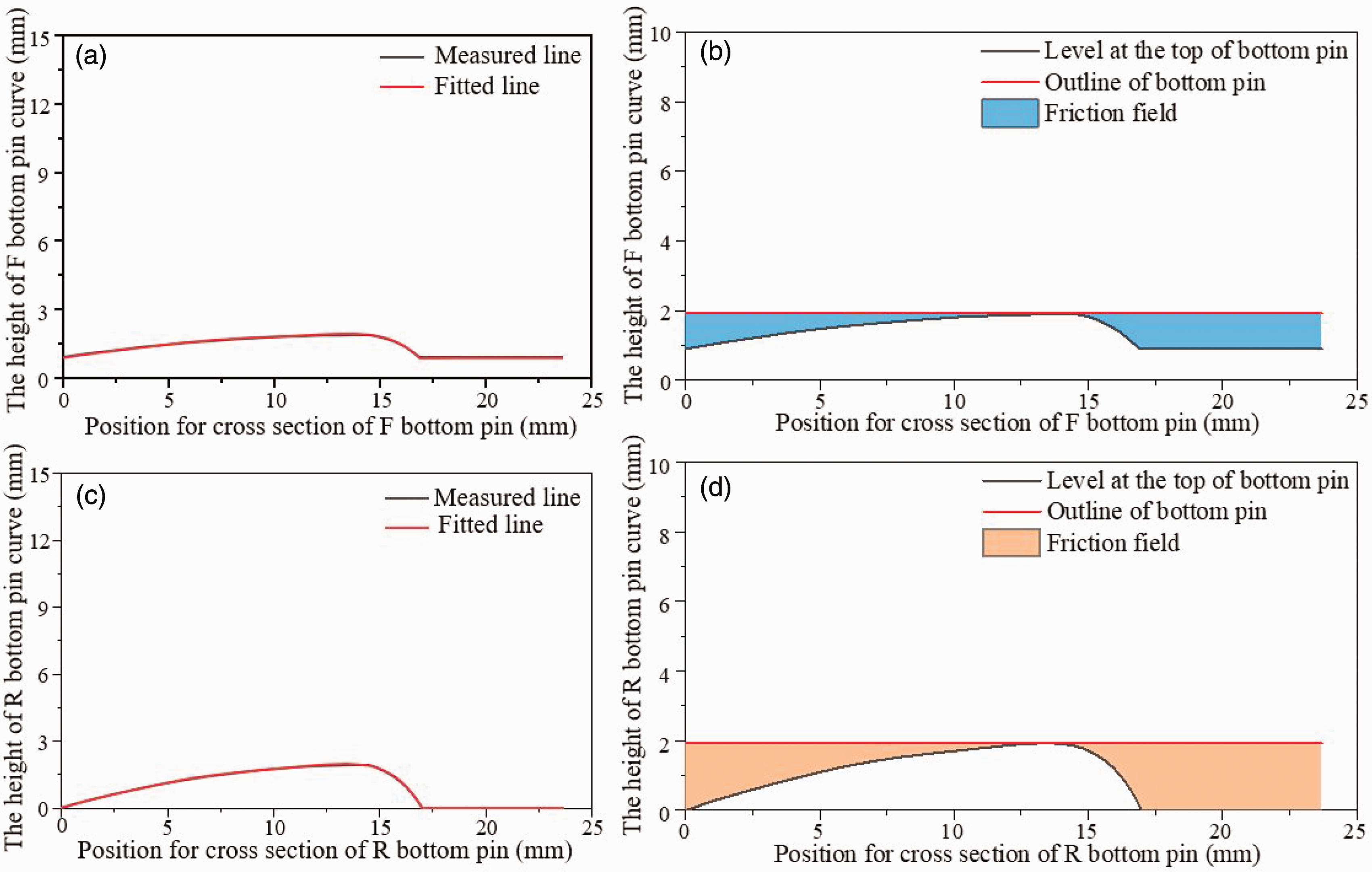
Two types of bottom pin arc curves: (a) the height of the F bottom pin curve; (b) F bottom pin friction field; (c) the height of the R bottom pin curve and (d) R bottom pin friction field.
The coefficients of each of the two bottom pin surface fitting functions

According to the basic polynomial rule, the higher the polynomial order, the higher the accuracy of the fit. Theoretically, the coefficients of a polynomial model can be obtained when the acquired data points are larger than the highest order of the constructed polynomial. However, when the amount of data is small, too high an order can bring about sharp fluctuations in the local point set. For this reason, the present position chooses a 7th degree polynomial complex curve fitting model. 

A simple schematic diagram of the grip space between the upper and bottom pin components is shown in Figure 3(b) and (d).
Assuming that at the zero point of the coordinate system, the spring is in a relaxed state, the degree of normal compression is the longitudinal coordinate of the curve, so the magnitude of the normal positive pressure can be expressed as


Then the difference in the magnitude of the normal positive pressure between the two bottom pins is

From the function curves in Figure 4, it can be seen qualitatively that two bottom pins will exert different applied forces on the fiber stands along the drafting motion, and the difference increases from the top of the bottom pin to two sides. A quantity analysis can be done by establishing mechanical equations with the micro element method.14
–16 Take any fiber strand micro element on the pressure surface of the bottom pin and construct a force analysis diagram (Figure 5(a) and (b)) to analyze the force:


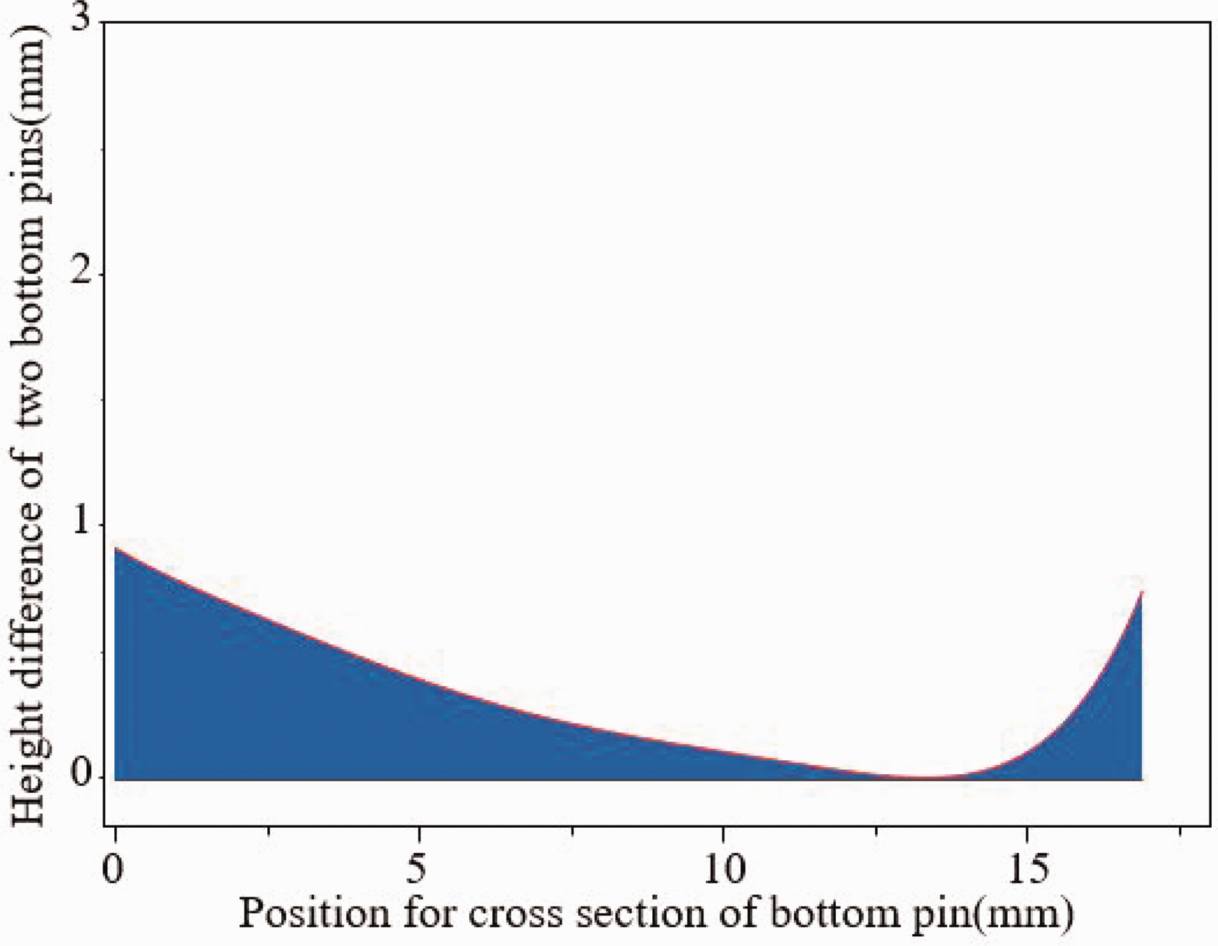
Trends in the size of the grip space.

Force analysis of the microfiber motion: (a) spatial mechanical analysis of the F bottom pin; (b) spatial mechanical analysis of the R bottom pin; (c) comparison of the arc lengths of the friction effect produced by the two bottom pins and (d) comparison of local amplification of the arc length of the friction effect produced by the two bottom pins.
As the value of α tends infinitely to 0 so by substituting and ignoring higher terms, the equation reduces to



Figure 5(c) shows the connection between 
Solving the differential equation, as





According to formula (15), the friction force is proportional to
Distribution of friction field on the fiber strand
Finite element modeling
The distribution of normal pressure determines the friction field, and the finite element model (FEM) was utilized quantitatively to analyze normal pressure on the bottom pins for comparing the differences in friction fields exerted on fiber strands.
Simplified model
The FEM study is analyzed using ANSYS Workbench. The entire drafting element is reasonably simplified after assuming that the bottom pin is compressed by the cradle, which leads to the fiber strand in the bottom pin friction field. The material of the bottom pins is aluminum alloy.
Mesh division
The two FEMs of bottom pins are meshed (Figure 6), and the sizes of the cells are the same. To avoid the influence of grid size on the simulation results, the F bottom pin is divided into 15,837 nodes with 2992 cells, while the R bottom pin is divided into 12,344 nodes with 2211 cells.

Model with the finite element method: (a) meshing of the F bottom pin model and (b) meshing of the R bottom pin model.
Field conditions
The surfaces of the two bottom pins are defined as fixed supports to limit the degrees of freedom. Different magnitudes of pressure are applied to the three surfaces of each of the bottom pins to simulate force acting on the bottom pins by the cradle.
Analysis and results
In Figure 7, the contours of equivalent strain, normal stress, and total deformation for the two bottom pin surfaces are presented. These contours provide a visual representation of the distribution of these parameters. The force on the contact surface of the bottom pin exhibits a gradient change, indicating that the influence of the friction field on the fiber strand gradually increases as it enters the curved surface section, and reaches its peak at the highest point of the bottom pin. This implies that the frictional effect on the fiber strand becomes stronger as it moves along the curved surface.
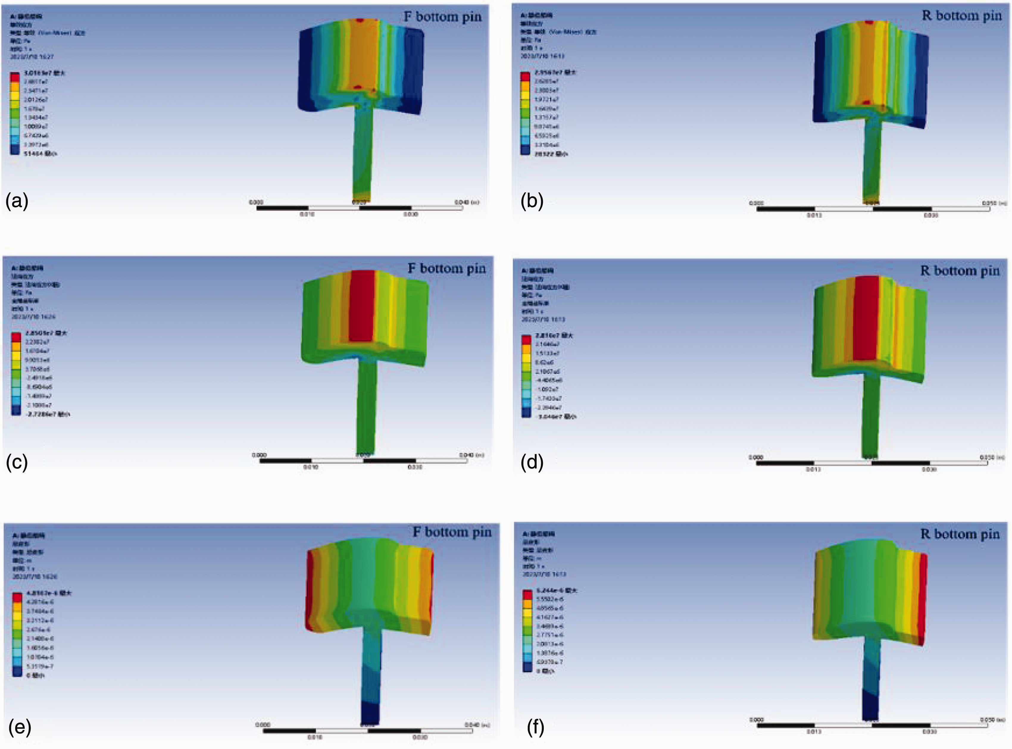
Simulation results for bottom pins: (a) equivalent force of the F bottom pin; (b) equivalent force of the R bottom pin; (c) normal stress of the R bottom pin; (d) normal stress of the R bottom pin; (e) total deformation of the F bottom pin and (f) total deformation of the R bottom pin.
Figure 7(c) and (d) depicts a slight variation in the microscopic deformation of the bottom pin. This indicates that the deformation of the bottom pin is relatively uniform and consistent across its surface. To represent the pressure distribution of the fiber strand on the bottom pin more intuitively, the product of the normal stress of the bottom pin cell and the area of the deformed cell is assumed to be the pressure. By multiplying the normal stress with the cell area, a more comprehensive representation of the pressure distribution is obtained.
In addition, the friction coefficient of the bottom pin surface is considered constant throughout the analysis. The normal pressure, in this context, serves as an indicator of the friction field between the bottom pins and the fiber strand.
Experimental details
Raw materials
The raw material was obtained from Anhui Huamao Textile Co., Ltd. and the weight of cotton roving was 930 tex at conventional moisture regain. The F and R bottom pins were also obtained from Huamao’s production workshop.
Methodology
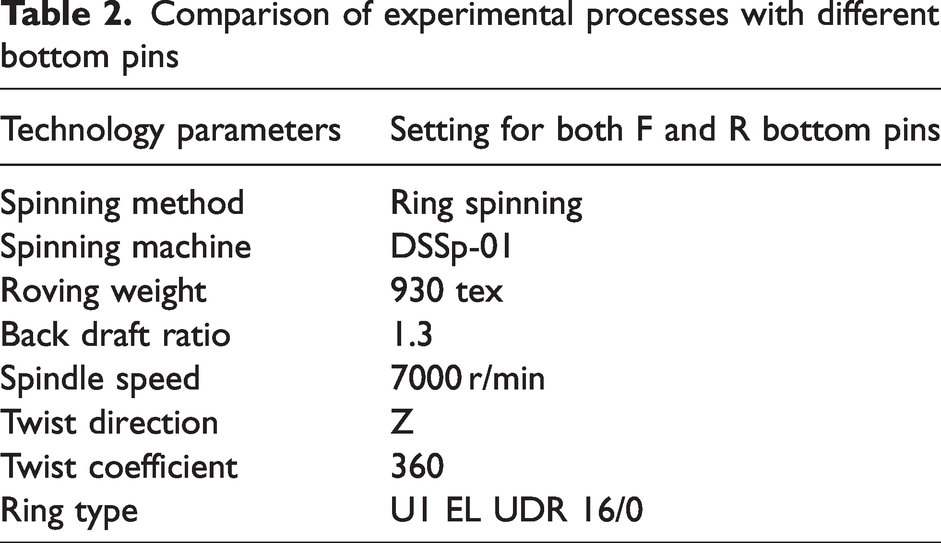
Cotton fibers were typically used to carry out experiments in this study and cotton yarns of 30 S, 40 S, 50 S, 60 S, and 70 S were spun with the F and R bottom pins (Figure 8), respectively. Spinning was carried out simultaneously on six spindles in a spinning machine, while 60 groups of yarns in total were produced with the same settings of spindle speed, draw multiplier in the back zone, twist direction, and twist coefficient (presented in Table 2).
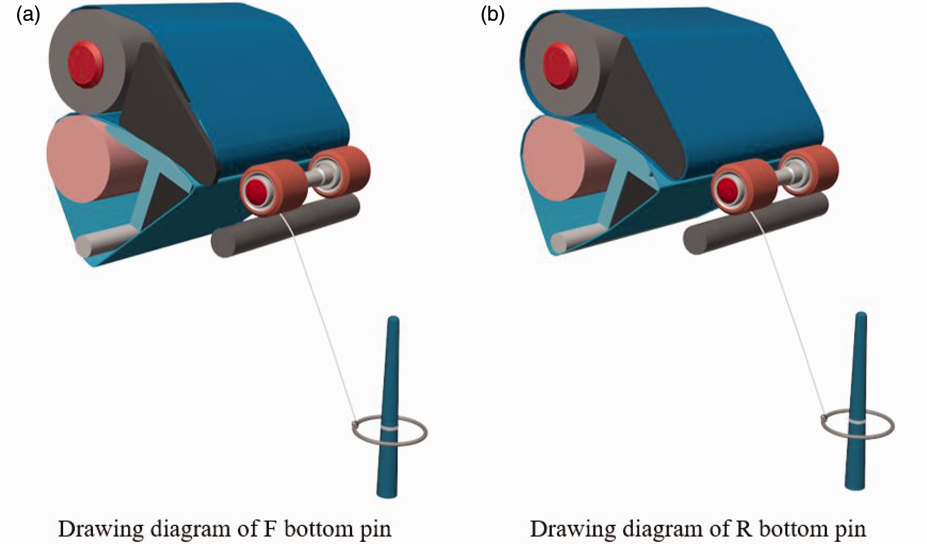
Spinning process flow chart: (a) spinning on the F bottom pin and (b) spinning on the R bottom pin.
Comparison of experimental processes with different bottom pins
Yarn testing
All yarn samples were subjected to conditioning under standard atmospheres (at a temperature of 20 ± 2°C and humidity of 65 ± 4% according to ISO 139:2005 Textiles – Standard atmospheres for conditioning and testing. Various test indices, including hairiness, strength, and unevenness, were evaluated for the yarn samples. The test results for these parameters were averaged to obtain representative values for each sample.
To assess yarn evenness, a CFE500 evenness tester was employed. The test was conducted using a test length of 400 m and a test speed of 400 m/min. Each bobbin yarn was tested once. For yarn strength testing, a YG068C automatic single yarn tester was utilized. The test length was set to 0.5 m, and each bobbin yarn underwent 10 tests. Yarn hairiness performance was measured using a H400 hairiness meter. The meter counted the hairiness of different lengths of yarn at a speed of 30 m/min. For calculation purposes, a segment length of 10 m was set, and five consecutive tests were performed to determine the average value. Statistical analysis of the data was carried out using SPSS 25 software, with a significance level set at 0.05.
Results and discussion
Effect of bottom pin cross-sectional morphology on yarn evenness
Yarn evenness refers to the consistency of yarn thickness and density along its length, encompassing variations in diameter and density throughout the yarn. Based on the information provided, Figure 9 demonstrates that yarns spun using F bottom pins exhibit better evenness compared with those spun using R bottom pins, with an average improvement of approximately 5%. This difference in evenness can be attributed to the characteristics of the F and R bottom pins. The curved surface of the F bottom pin is smaller and smoother than that of the R bottom pin. As a result, there is a wider contact area between the fiber strand and the top pin, creating a larger friction field. This enhanced friction field contributes to the improved longitudinal transport stability of the main fibers, and better control of transverse free fibers. In the main drafting area of the F bottom pin, the three-dimensional force exerted on the fiber strand allows for flexible control of one end of the fiber. This reduces the disturbance caused by accelerating fibers on the unaccelerated fibers in the rear, minimizing accidental slippage between fibers.
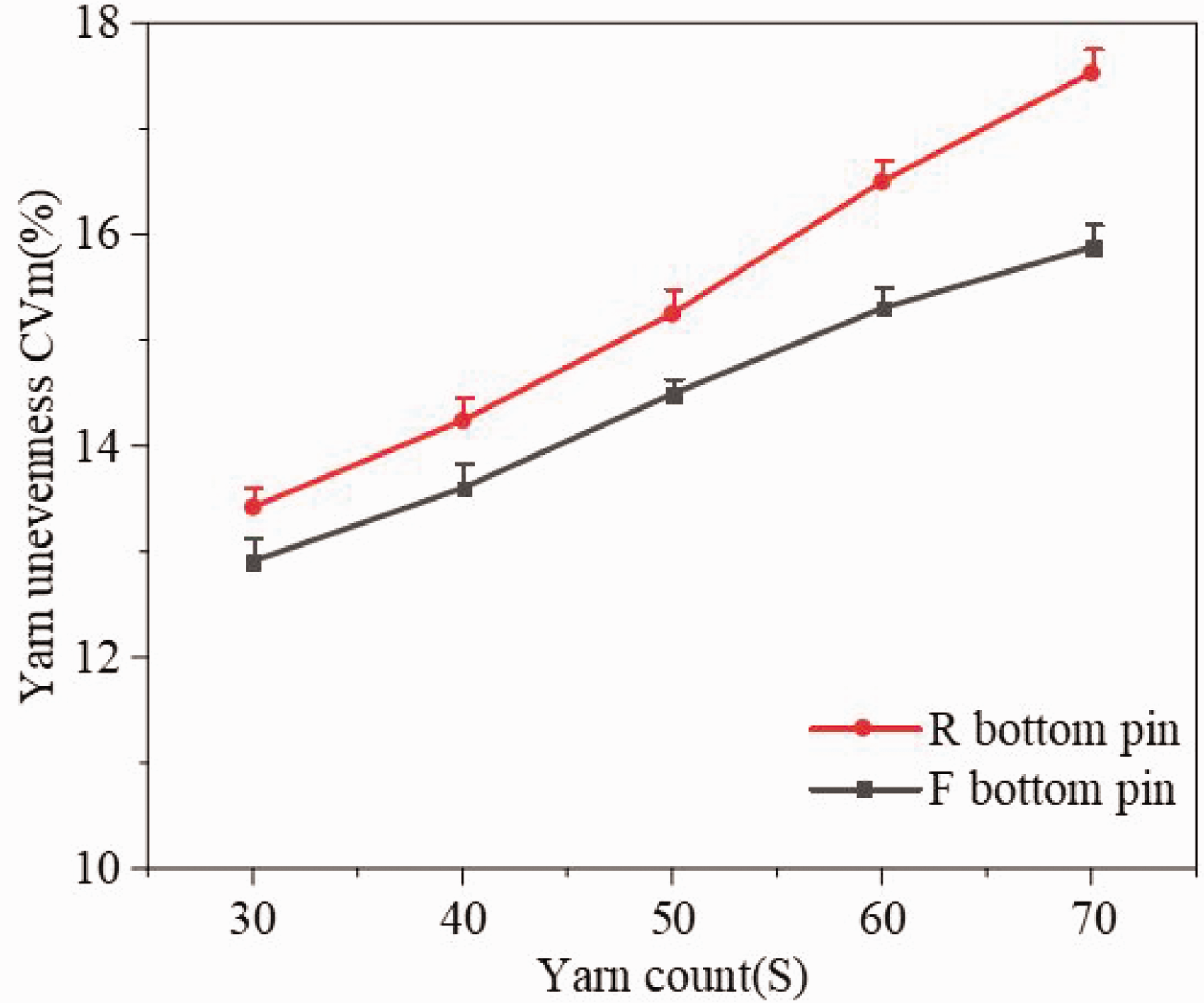
Yarn unevenness test.
In addition, the greater friction field in the elastic nip, combined with the friction between fibers along the drafting direction, helps to straighten and align the fibers. The transition section between the curved section and the flat section is also smoother for the F bottom pin. This facilitates a more uniform and stable extraction of fibers from the fiber strand, leading to improved yarn evenness.
Yarn evenness tends to decrease (unevenness increases) as the yarn count increases. This is because when spinning higher count yarns with fewer fibers in the fiber strand, the friction between accelerated fibers and slower fibers decreases. The same applies to the friction between the fiber strand and the elastic nip. This reduction in the friction field’s effect leads to a decrease in the control force exerted on the fibers during the pulling-out process, resulting in uneven distribution. As a consequence, the movement of fibers becomes unstable, negatively impacting yarn evenness. However, it is observed that appropriate enhancement of the friction field in the elastic nip, achieved by selecting the appropriate bottom pin, can improve yarn evenness (as presented in Table 3). By enhancing the flexible control on the fiber strand, the friction field can be optimized, mitigating the negative effects mentioned earlier.
Yarn evenness test
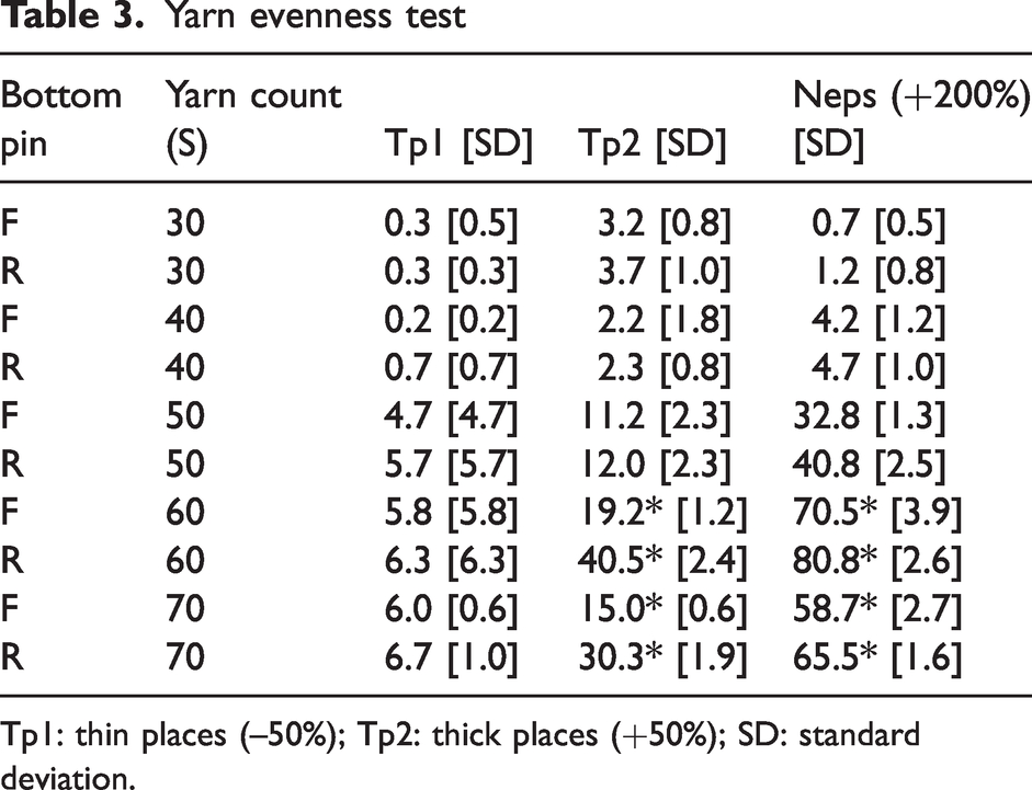
Tp1: thin places (–50%); Tp2: thick places (+50%); SD: standard deviation.
As the yarn count increases, the difference in evenness between yarn spun with the F bottom pin (F yarn) and yarn spun with the R bottom pin (R yarn) becomes more prominent. This difference ranges from 4.3% to 9.8% when the yarn count changes from 30 S to 70 S. This observation can be explained by the stronger friction field created by the F bottom pin. The increased friction field helps reduce uncontrolled longitudinal drawing of the fiber strand, which is typically caused by the higher yarn count. By restraining the deterioration of yarn evenness, the F bottom pin contributes to a larger difference in evenness between F yarn and R yarn as the yarn count increases. Similarly, the significant difference between F and R yarns can be observed in terms of thick places and neps for high-count yarns. This difference is attributed to the enhanced friction field and better control provided by the F bottom pin. However, there is no significant difference in thin places between the two types of yarns, as the friction field may not have a substantial impact on thin areas.
Effect of bottom pin cross-sectional morphology on yarn hairiness
According to the theory of yarn formation, the size of the spinning triangle and the internal movement state of the fibers are the main factors influencing the generation of hairiness. 17 After the completion of drafting, the fiber strand enters the front nip, where it forms a flat two-dimensional structure that directly determines the size of the spinning triangle, thus impacting yarn hairiness. In Figure 10, it can be observed that the number of harmful hairiness, specifically 2 mm hairs (denoted as S2) and 3 mm hairs (denoted as S3), is higher in F yarns. This can be attributed to the stronger friction field created by the F bottom pin, which results in a wider fiber strand. However, the friction field in this case only controls the edge fibers without effectively collecting the transverse fibers. As a consequence, there is difficulty in converging the fibers on the edge and surface layer of the fiber strand toward the center. This combined effect leads to an increase in the size of the spinning triangle, ultimately deteriorating yarn hairiness.18,19
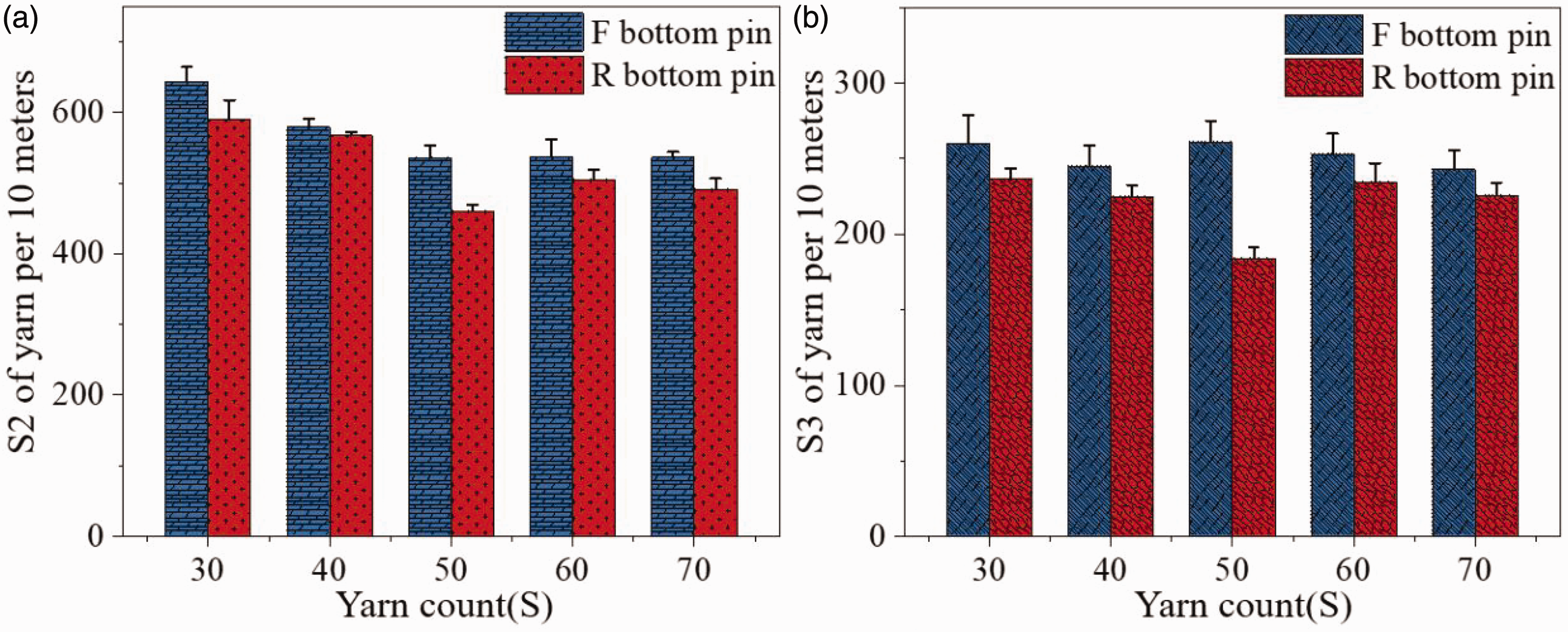
Yarn hairiness test: (a) S2 comparisons for yarns with different bottom pin types and yarn counts and (b) S3 comparisons for yarns with different bottom pin types and yarn counts.
Effect of bottom pin cross-sectional morphology on yarn strength
In Figure 11(a), it is evident that the strength of F yarns is higher than that of R yarns at the same yarn counts. The yarn strength is primarily determined by factors such as fiber material, yarn structure, and yarn evenness. 20 When fibers are straighter, more parallel, and evenly distributed within the yarn, the yarn strength tends to be higher. As mentioned earlier, the F bottom pin, with its wider friction field and stronger control on fibers during drafting, promotes better fiber parallelism and improved yarn evenness. Consequently, the yarn strength of the F yarn is enhanced, surpassing the strength of the R yarn.

Yarn strength test: (a) comparison of breaking force for F and R yarns with different counts and (b) comparison of breaking elongation for F and R yarns with different counts.
Furthermore, Figure 11(b) demonstrates that yarn strength tends to decrease as the yarn count increases. This can be attributed to the number of fibers present in the yarn strand, and the cohesion between these fibers. Higher yarn counts are composed of a smaller number of fibers, maintaining the same twist coefficient. This reduction in the number of fibers results in decreased cohesion within the yarn, leading to a decrease in yarn strength. In addition, it is worth noting that there is no significant difference in the breaking elongation between F and R yarns. Breaking elongation refers to the extent to which a yarn can be stretched before it breaks. In this case, the type of bottom pin does not have a noticeable impact on the breaking elongation of the yarn.
Conclusions
Through mechanical modeling and finite element method to analyze the size and distribution of the friction field generated by two different bottom pins, it has been discovered that the elastic friction field in the drafting process is directly influenced by the curved and flat transition section of the bottom pins.
A smaller radius of the curved section and a smoother transition in the flat section result in a wider friction field, which provides stronger and more flexible control over the fiber strand during drafting. This enhanced control contributes to better yarn evenness and higher yarn strength. However, the wider friction field also leads to a wider fiber strand, increasing the size of the spinning triangle, and promoting more yarn hairiness. Furthermore, as the yarn count increases, yarn evenness and strength tend to decrease, while the hairiness remains consistent.
By understanding the relationship between the size and distribution of the friction field generated by different bottom pins and their effects on yarn properties, advancements can be made in optimizing spinning processes and equipment to enhance yarn properties.
Footnotes
Acknowledgements
The author(s) wish to acknowledge Junlong Ni, Shengya Hu, Wei Ye, Chuang Ding and Renfa Jin for their great assistance with cotton sampling for this work. The author(s) are also grateful to the spinning group in the State Key Laboratory of New Textile Materials and Advanced Processing Technologies at Wuhan Textile University for technical support.
Declaration of conflicting interests
The author(s) declared no potential conflicts of interest with respect to the research, authorship, and/or publication of this article.
Funding
The author(s) disclosed receipt of the following financial support for the research, authorship, and/or publication of this article: This work is supported in part by Wuhan Textile University Funding for cultivating National Natural Science Foundation of China, project No: xjj-2023-056, in part by the National Natural Science Foundation of China, project No: 52203373.
