
Abstract
In this work, the effects of dynamic mold temperature control (DMTC) on melt pressure, cellular structure, and mechanical properties of microcellular injection molding (MIM)-molded parts are investigated experimentally. It is found that with the increase of the mold temperature, the duration of foaming pressure in the cooling stage increases. Meanwhile, the average cell diameter and cell diameter dispersion increases as well as the cell density decreases in MIM molded parts. The turning point of mold temperature after which the foaming pressure in the cooling stage and the cellular structure in MIM molded parts generate a significant change is around the glass transition temperature of the used plastic material. Under DMTC conditions, with the increase of mold temperature, the tensile strength, flexural strength, and impact strength of MIM molded specimens of single gate without weld line change a little, while the tensile strength, flexural strength of MIM molded specimens of double gates with weld line increase obviously. When the mold temperature increases to 120°C and over, the tensile strength, flexural strength of MIM molded specimens of double gates with weld line reach an equivalent level of specimens of single gate without weld line.
Keywords
Introduction
Microcellular foamed plastics have lots of advantages including lightweight, high strength-to-weight ratio, excellent cushioning and insulation performance, and higher strength than conventional foamed plastics. In recent years, they have been widely used as automobile inner decorations, sports apparatuses, packaging and building materials, electrical elements, and tissue engineering scaffolds. 1 -4 The main approaches to fabricate microcellular foamed plastics are batch foaming, 5,6 extrusion foaming, 7,8 and injection foaming. 9 -11 Among them, injection foaming or microcellular injection molding (MIM) can produce a microcellular plastic part with complex shape once, reduce energy consumption, shorten molding cycle, and improve the dimensional accuracy of the molded product. Thus, MIM is considered as the most promising technology.
Although the MIM technology has the above advantages, the microcellular plastic parts molded using MIM still have some shortcomings, such as rough surface, uneven inner cellular structure, and poorer mechanical properties than solid injection molded parts, 12 -14 seriously limiting its large-scale application. To solve the existing problems, many studies were conducted and a series of auxiliary techniques were proposed to improve the quality and performance of MIM molded parts. For example, focusing on the rough surface quality of MIM molded parts, Yoon et al., 15 Chen et al., 16,17 and Lee et al. 18 successively proposed a kind of mold insulation treatment technique and utilized PEEK (polyetheretherketone), 82%PET (polyethylene terephthalate) + 18%PC (polycarbonate), PET, and PTFE (poly tetra fluoroethylene) as the thermal insulation materials onto the mold cavity surface and significantly improved the glossiness of MIM molded parts. Besides, Chen et al. 19,20 used induction heating and steam heating to heat the mold before the melt injecting; Lee et al. 21 presented a method by reducing the degree of gas super saturation; Chen et al., 22 Ruiz et al., 23 and Li et al. 24 established a gas counter pressure system respectively; and Hou et al. 25 proposed a gas-assisted MIM process. These above efforts also brought good effects on the surface quality of MIM molded parts. For the problems of uneven inner cellular structure and the resulting poor mechanical properties of MIM molded products, many researchers firstly attempted to improve or solve the problems by adjusting the procedure parameters such as shot size, 26 injection speed, 27 melt temperature, 28 or adding fillers to the resin. 29,30 Then they also developed various auxiliary methods combined with MIM process. For instance, Bledzki et al. 31 applied precision mold opening and gas counter pressure to MIM and produced a microcellular foamed PC product with uniform inner cell structure and enhanced the notch impact strength of the product, Huang et al. 32 constructed a microcellular injection–compression molding technology and significantly improved the inner cellular structure of MIM molded parts by compressing the foaming melt in the mold, and Ruiz et al. 33,34 used a breathing mold technology for molding microcellular plastic products and improved the internal cell size, cell density distribution, and the compression young’s modulus of MIM molded products.
In the above auxiliary processes of MIM, the technique of changing the mold temperature in the filling stage, here we called dynamic mold temperature control (DMTC), is one of the most promising auxiliary strategies. 35,36 This is due to its outstanding amelioration effect on MIM molded product’s quality and minor modification to the original processing equipment. In the field of traditional injection molding, the DMTC has experienced a long time of development, especially in recent years, it has obtained a great progress and found a wide application in the elimination of weld line, 37,38 improvement of optical performance, 39,40 enhancement of dimensional accuracy, 41,42 and reduction of surface floating fiber of molded fiber-reinforced plastic parts. 43 Therefore, a growing attention has been paid to DMTC technology in MIM research field. Recently, Xiao et al. 44 developed a rapid thermal cycling molding technology with electric heating and water cooling to eliminate the surface defects of microcellular injection molded parts, the results showed that the microcellular polyoxymethylene cover plates with glossy appearance comparable to the solid counterpart can be molded when the mold temperature is raised above 150°C.
In fact, the rough surface of MIM molded parts is mainly caused by the broken bubble marks on the part surface, and this broken bubble marks are also a special outer cellular structure morphology of MIM molded parts. 45 In our previous studies, 46,47 it was found that the surface bubble marks of MIM molded parts are caused by the bubbles formed in “foam during filling” process near the melt flow front, which are stretched, broken, pushed out, and turned over to both sides of the melt flow by the shear flow and fountain flow behaviors, then contacted with the cold mold cavity surface and solidified quickly. It was also found that the key factor for making the melt to foam during filling or after filling is the melt pressure and pressure distribution in the injection filling stage, that is, the melt pressure and variation in different positions in MIM molded part determines its foaming process and its final cellular structure of these positions. In addition, the differences of cellular structure in MIM molded parts usually cause a change of mechanical properties, the smaller the cell size is and the more uniform the cell distribution is, the better the mechanical properties of MIM foamed part are. Thus, it can be seen that there is a certain interaction effect between the problems of rough surface, uneven cellular structure, and poor mechanical properties of MIM molded parts. In conclusion, for the implementation of any kind of auxiliary processes including DMTC, no matter their original intentions, they will have a systematic and comprehensive influence on MIM process and MIM molded parts.
However, the existing MIM auxiliary processes, of course, including DMTC technology, are mainly proposed and studied only from a specific quality problem of MIM molded parts, and few studies have been done systematically and comprehensively from the overall influences of the auxiliary process on MIM. At present, research and application about MIM under DMTC are still only focusing on the improvement of surface qualities. There are no comprehensive reports about the effects of DMTC on MIM process, especially about the effects on melt pressure in MIM process and the cellular structure and mechanical properties of MIM molded parts. Meanwhile, the influence mechanism of mold temperature via DMTC on the cell formation processes of MIM molded parts is still not clearly revealed, and the control strategies of MIM process and qualities of molded parts under DMTC condition are still not completely established. All of these problems urgently need to be studied systematically and intensively.
In this work, a set of MIM mold with electrical heating and water cooling was designed and manufactured, and an experimental test line of MIM with DMTC was constructed. The effects of DMTC on MIM process was investigated experimentally. The influence rules of mold temperature via DMTC on melt pressure in MIM process and the cellular structure and mechanical properties of MIM molded parts were revealed. The influence mechanism of high mold temperature under DMTC conditions on melt pressure, cellular structure, and mechanical properties of MIM molded parts were investigated. The turning point of mold temperature after which the melt pressure in MIM process and the cellular structure of MIM molded parts generates a significant change was also found.
Experimental section
Designed part and injection mold
To systematically investigate the effects of DMTC on melt pressure, cellular structure, and mechanical properties of MIM molded parts, a microcellular part consisting of specimens and rectangular plates was designed, and the corresponding MIM mold with DMTC was also developed. The structure of the designed part and developed MIM mold with DMTC is shown in Figure 1.

Structure of the designed part and developed MIM mold with DMTC: (a) part and (b) mold.
Figure 1(a) shows the designed MIM part. It consists of five ASTM D638 standard tensile specimens (four specimens of single gate without weld line, one specimen of double gates with weld line), five ASTM D5023 standard bend specimens (four specimens of single gate without weld line, one specimen of double gates with weld line), four ASTM D256 standard impact specimens (single gate, two specimens of V shape notched, and two specimens unnotched), and four rectangular plates with different thickness stiffeners.
Figure 1(b) shows the developed MIM mold with DMTC. The mold temperature control mode is electric rod heating and water cooling. The mold is assembled with 18 electric rods in the mold core. The electric rods come from MISUMI (type of MCHPA). The diameter of rod is 5.9 mm with a heating watt density of 25 W/cm2. The distance from the electric heating rod channel center to the mold surface is 5 mm. The cooling water of approximately 15–30°C is used as the cooling medium of the mold. The cooling water channel has a diameter of 8 mm and a distance of 54 mm from the channel center to the mold surface, as shown in Figure 1(b)-I. The electric rods and cooling water channels have a perpendicular layout to enhance the structural strength and stiffness of the mold, reduce the deformation of the cavity, and prolong the service life. In addition, three pressure sensors are assembled in mold cavity for real-time gathering of the melt pressure using a mold marshalling system of Futaba EPA-002, as shown in Figure 1(b)-II.
DMTC system and injection test line
Based on the developed MIM mold with electric rod heating and water cooling, the authors developed a DMTC system, 48 as shown in Figure 2. As can be seen from Figure 2, the whole system consists of six main components: air compressor, cooling tower, valve exchange device, injection molding machine, electric heating mold, and control and monitor unit. The valve exchange device mainly contains booster pump, water inlet valve, gas inlet valve, filter, pressure regulating valve, pressure gage, and so on. The control and monitor unit mainly contains programmable logic controller (PLC), touch screen, and corresponding control circuits. When the mold is heated, the PLC sends out control instructions to suction the contactor in the circuit of electric rods for heating the mold. When the mold heating is finished, the PLC sends out closing instructions to the contactor and meanwhile lets the water inlet valve diversion, then the cooling water enters into the cooling channels of the mold for cooling the mold. Finally, when the mold cooling is finished, the PLC sends out control instructions again to replace the water inlet valve to cut off the cooling water supply and open the gas inlet valve, the compressed air is forced into the cooling channels by the air compressor to drain out the remaining cooling water. Throughout the working cycle, the PLC keeps communications with the control system of the injection machine to make sure every action compatibly. Besides, the thermocouples assembled in the mold can feed back real-time mold temperature signals to PLC, as a basis for controlling the mold temperature.
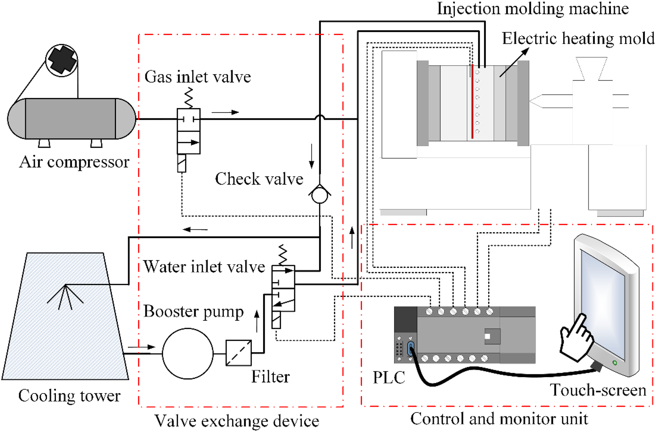
Schematic diagram of the developed DMTC system.
By connecting the developed DMTC system to the MIM machines, a test line of MIM with DMTC was finally constructed, as shown in Figure 3. It mainly consists of injection molding machine, DMTC system, electric heating mold, supercritical fluid (SCF) metering and injecting system, and mold marshalling system. The injection molding machine has a clamping force of 3200 kN, the maximum injection pressure of 182 MPa, a screw diameter of 60 mm, and a theoretical shot volume of 791 cm3 (based on polystyrene [PS]). The SCF metering and injecting system has a gas injecting pressure range of approximately 10–25 MPa and a mass flow rate of approximately 0–1.1 g/s. The injection molding machine is equipped with a shut-off nozzle, Herzog GN2, and bottled industrial nitrogen (99.99% purity) is used as the physical blowing agent.
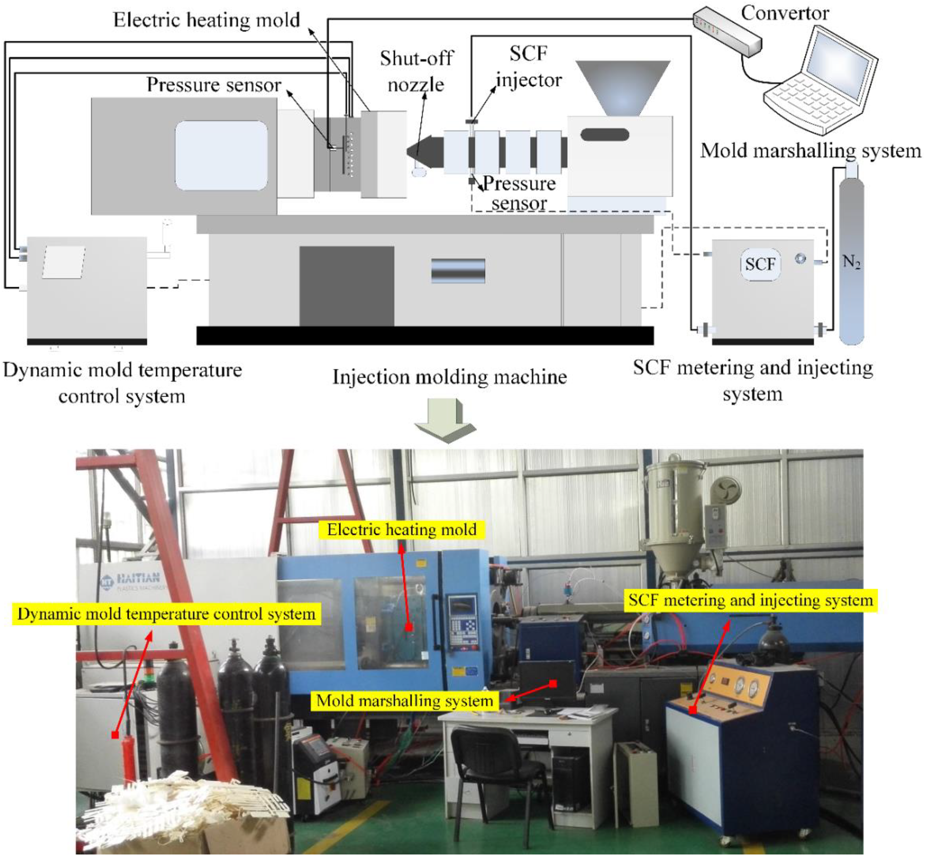
Structural diagram of the constructed MIM test line with DMTC.
Molded part and material
After injection using the above electric heating microcellular injection mold and test line, the molded parts with the shape shown in Figure 4 can be obtained, where the impact specimen has a dimension of 65 × 12.7 × 3.2 mm3 (ASTM D256), the bending specimen has a dimension of 127 × 13 × 3.2 mm3 (ASTM D5023), the tensile specimen has a dimension of 165 × 12.7 × 3.2 mm3 (ASTM D638), the bigger rectangular plate has a dimension of 170 × 60 × 4 mm3, and the smaller rectangular plate has a dimension of 87 ×60 × 4 mm3, respectively. The material used in the experiments is acrylonitrile–butadiene–styrene copolymer, LG Chemical HF380, with a melt flow index of 43 g/min at 230°C and a density of 1.04 g/cm3 at room temperature. Before injection, the material was dried at 80°C for 4 h to remove moisture.

Geometry and size of the molded part.
Experimental design
To systematically investigate the effects of DMTC on melt pressure, cellular structure, and mechanical properties of MIM molded parts, after the molding process has run steadily, the MIM experiments under mold temperature of 30°C were conducted firstly to obtain the molded parts in conventional low mold temperature (30°C). Then, increasing the mold temperature gradually using the DMTC system and keeping the other processing conditions unchanged, the molded parts in mold temperatures of 60°C, 90°C, 120°C, and 150°C were obtained, respectively. The screw injection displacement of 80 mm was set as the shot size in this article, corresponding to the molded part filled completely, without short shot and flash. The processing conditions for MIM process with DMTC in this study are summarized in Table 1.
Processing conditions for MIM process with DMTC.
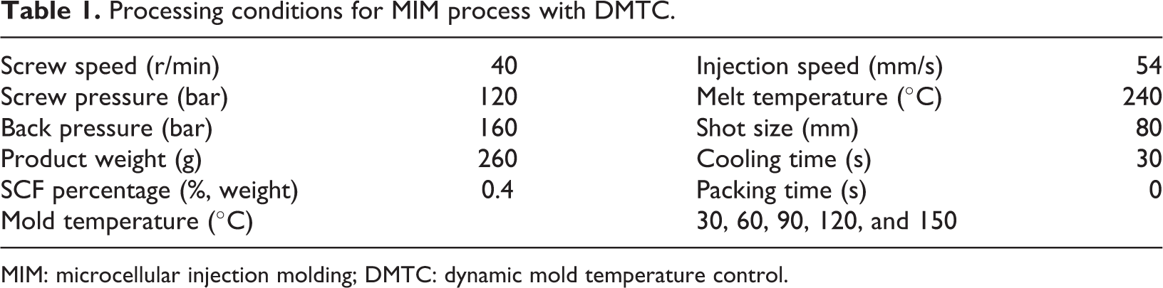
MIM: microcellular injection molding; DMTC: dynamic mold temperature control.
Characterization and testing
For gathering of melt pressure in MIM process, the injection starting moment is set as the zero point of the mold marshalling system, the total sampling time is 30 s, and the sampling interval is 0.05 s. For the MIM molded parts under different mold temperatures using DMTC in this study, the tensile specimens with melt pressure gathering are chosen as cellular structure observation objects. The samples are cut off in three positions, which is corresponding to the two melt pressure sensor located positions and their middle positions, and then observed by a scanning electron microscope (SEM, JEOL, Japan, JSM-6610LV). All of the SEM samples are fractured in liquid nitrogen, then the fractured surface of every samples is coated with an approximately 10-nm-thick layer of gold, and observed with a voltage of 15 kV. In this way, the changes of cellular structure in molded parts under different mold temperatures are obtained. Simultaneously, the MIM molded tensile specimens with and without weld line, bending specimens with and without weld line, notched, and unnotched impact specimens are chosen as the mechanical properties testing objects. An electronic universal testing machine (SANS GMT5105) and an electronic pendulum impact testing machine (XJC-5D) are used to obtain the mechanical properties of MIM molded parts under different mold temperatures. The characterization and testing methods of MIM molded parts under DMTC is shown in Figure 5.
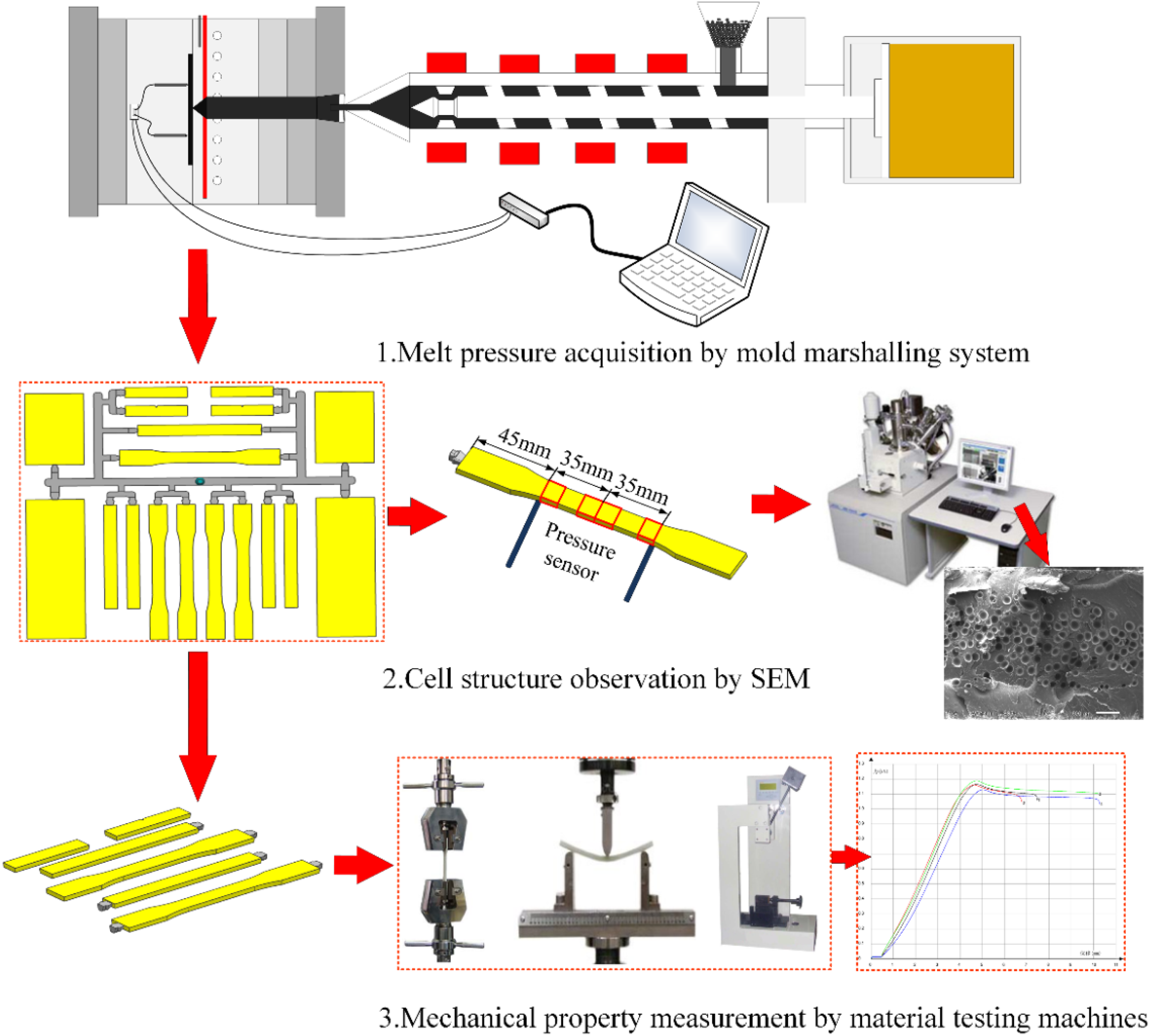
Characterization and testing methods of MIM molded parts under DMTC.
To further study the effect of DMTC on the cellular structure of MIM molded parts, a statistical analysis on the SEM pictures of the above observed cross sections is conducted using the image processing software Image-Pro Plus. The statistic cell number is more than 100 in the selected area to ensure the reliability of statistical results. The average cell diameter, cell density, and cell diameter dispersion are calculated using equations (1) to (3). The thickness of unfoamed skin layer is measured directly.


where N
0 is the cell density and its unit is cm−3; n is the cell number of the selected area; M is the magnification of SEM pictures; A is the area value of the selected area and its unit is cm2; Di
is the diameter of single cell and its unit is µm;
Results and discussion
Effect of DMTC on melt pressure in MIM process
To verify the reliability of the mold marshalling system and contrastively analyze the melt pressure variation in MIM process, the conventional injection molding (CIM) process under low temperature of 30°C is conducted firstly, and the changes of melt pressure gathered by the three pressure sensors are shown in Figure 6(a). It can be seen that during the CIM, the melt pressures in the three gathering positions all increase quickly after the melt is injected into the mold. The melt pressure reaches the maximum value of approximately 9–11 MPa in about 2 s, then falls rapidly after the injection is finished, and finally drops to zero at the time of 4 s. The melt pressure variation gathered by mold marshalling system has a good accordance with the well-known melt pressure conditions in CIM. 45 It is indicated that the used mold marshalling system works well and the gathered data are reliable.

Melt pressure variation in CIM and MIM with different mold temperatures gathered by mold marshalling system: (a) CIM: mold temperature – 30°C; (b) MIM: mold temperature – 30°C; (c) MIM: mold temperature – 60°C; (d) MIM: mold temperature – 90°C; (e) MIM: mold temperature – 120°C; and (f) MIM: mold temperature – 150°C.
Using the mold marshalling system to gather the melt pressure in the filling and cooling stage of MIM process with DMTC, the obtained results under different mold temperatures are shown in Figure 6(b) to (f). It can be seen that during the MIM process, the melt pressure variations in filling and cooling stage are obviously different from CIM. The peak value of melt pressure in filling stage of MIM process is smaller than that of CIM, the peak value of melt pressure in filling stage of MIM with mold temperature of 30°C is about 6.7 MPa, as shown in Figure 6(b), and it is approximately 3–4 MPa less than the peak value of the melt pressure in filling stage of CIM under the same mold temperature condition. This is because that in MIM, the SCF nitrogen is dissolved into polymer melt, will decrease the viscosity of the melt, and will improve its filling ability significantly. Thus, in the same injection speed condition, the injection pressure used in MIM is smaller than that in CIM, and accordingly, the melt pressure in the MIM mold is also reduced. In addition, in the cooling stage of MIM, the melt pressure has an obvious difference from CIM, that is, the melt pressure is not zero, while keeps a certain value until the cooling is finished, as shown with the mark of P foam in Figure 6(b) to (f). This is due to that when the melt injection is finished in MIM, the melt will enter into “foaming after filling” stage 46 and undergo a foaming process from cell nucleation to cell growing.
From Figure 6(b) to (f), it can be found that the mold temperature has a significant influence on the melt pressure in the filling and cooling stage of MIM process. In the filling stage of MIM process, the peak value of melt pressure decreases with the increase of mold temperature. Specifically, when the mold temperature in the filling stage increases from 30°C to 150°C, the peak value of melt pressure decreases about approximately 1.5–2 MPa. The reason is that the increase of mold temperature further improves the flowability and reduces the injection pressure. In the cooling stage of MIM, the melt pressure exhibits a series of changes with the increase of mold temperature. When the mold temperature is 30°C and 60°C, the melt in the cooling stage of MIM foams after melt filling and produces a certain foaming pressure, but the foaming pressure gradually decreases to zero in the middle or late period of cooling stage, as shown in Figure 6(b) and (c). This phenomenon demonstrates that when the mold temperature is lower (i.e. 30°C and 60°C), the melt has a shorter foaming process in the cooling stage and it only dominates part time of cooling stage. When the mold temperature increases to 90°C, the melt foaming pressure always exists in the whole cooling stage and almost no zero pressure value appears during cooling, the foaming pressure is gradually decreased, but the decreasing trend becomes weaker, as shown in Figure 6(d). This indicates that the melt foaming process has basically dominated the whole cooling stage at the mold temperature of 90°C. When the mold temperature is increased further to 120°C and 150°C, the melt foaming pressure obviously and continuously exists during the cooling stage, and the pressure value increases slightly comparing to the foaming pressure under low mold temperature conditions. More even, an increasing trend appears in the late cooling stage under mold temperature of 150°C, as shown in Figure 6(f). This illustrates that under high mold temperature, the melt foaming process in the cooling stage dominates the whole cooling stage.
All the above results indicate that with the increase of mold temperature using DMTC, the melt foaming process in the cooling stage of MIM process changes from partly dominating the cooling stage to totally dominating the cooling stage, and the foaming strength of the melt also increases slightly. This is because that the increase of mold temperature in the filling stage slows down the mold cooling speed in the cooling stage, causing the melt temperature in the cooling stage decrease slowly and the melt strength increase slowly, thus giving the melt a longer time to foam. In addition, from Figure 6(b) to (f), it also can be found that with the increase of the mold temperature in the filling stage of MIM, the instability of melt foaming pressure in the cooling stage increases and a pressure fluctuation appears. This phenomenon is caused by an uneven melt foaming process in the cooling stage due to the increase of mold temperature.
Effect of DMTC on cellular structure of MIM molded parts
Figure 7 shows the changes of cellular structure in MIM molded tensile specimens with melt pressure gathering and of single gate without weld line under different mold temperatures. The sampling positions are the positions of the two melt pressure sensor located and their middle position. It can be seen that with the increase of mold temperature, the cell size in the interior of MIM molded parts increases gradually. Especially, when the mold temperature increases to 90°C and over, the cell diameter in the central area of the three observed cross sections increases obviously compared with the cells in the molded parts under mold temperature of 30°C and 60°C. Big cells with diameter of more than 100 µm begin to appear. With the further increase of the mold temperature, the big cells gradually propagate from the center of the cross section to the upper and lower unfoamed skin layer. In addition, when the mold temperature increases to 90°C and over, the cell density in the observed cross sections decreases, and the uniformity of cell size distribution decreases too (as shown in the red circle of Figure 7). Particularly, for the observed cross section of far from gate position, when the mold temperature increases to 120°C and 150°C, both a small and a big bubble accumulation areas are clearly formed, respectively. Finally, for the unfoamed skin layer of MIM molded parts, under lower mold temperature of 30°C and 60°C, there is obvious boundary line between unfoamed skin layer and foamed core region, while with the increase of mold temperature, the boundary line gradually becomes unobvious, and even some little bubbles begin to appear in the unfoamed skin layer when the mold temperature increases to 150°C.

Cellular structure of MIM molded parts under different mold temperatures.
By considering the effect of DMTC on melt pressure in MIM process, it can be found that when the mold temperature increases to 90°C using DMTC, the melt foaming process begins to dominate the whole cooling stage and the cellular structure of molded parts under the corresponding conditions begins to change significantly, the cell size increases and cell density decreases obviously. Thus, it can be known that in the processing conditions of this article, with the increase of mold temperature via DMTC, the turning point of mold temperature after which the melt pressure and cellular structure generate a significant change is around 90°C. This turning point is exactly corresponding to the glass transition temperature of the used material. Therefore, it can be concluded that when the mold temperature increases to the glass transition temperature of polymer material using DMTC in MIM process, the melt foaming process in the cooling stage will be lengthened obviously and the cellular structure of molded parts will be changed significantly.
Using the image processing software Image-Pro Plus, the cellular structures of MIM molded parts under different mold temperatures shown in Figure 7 are calculated and measured. Figure 8 shows the variation of the average cell diameter, cell density, cell diameter dispersion, and thickness of unfoamed skin layer of molded parts under different mold temperatures in the fractured surfaces of the two melt pressure sensor located and their middle positions.
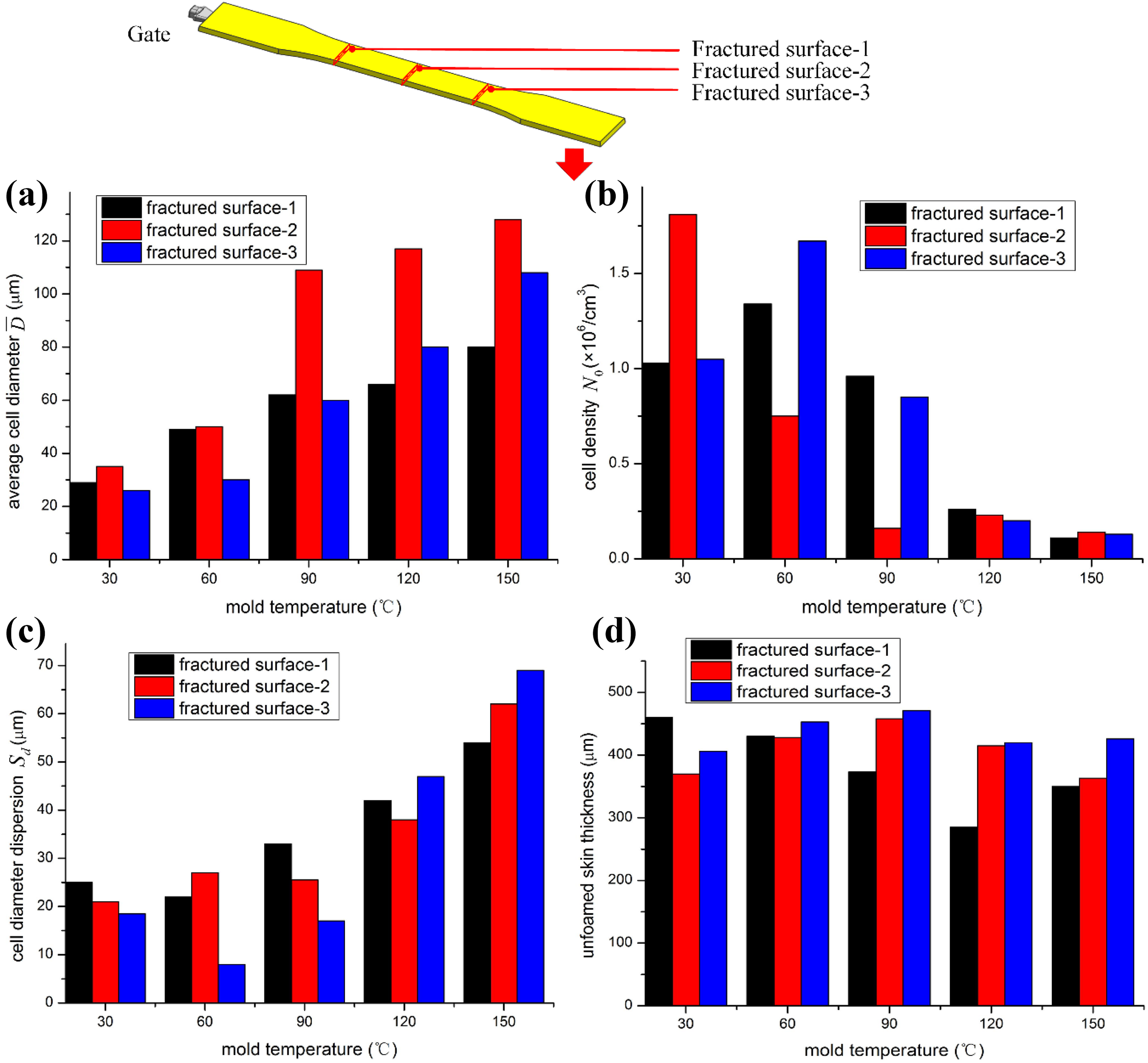
Variation of the average cell diameter, cell density, cell diameter dispersion, and thickness of unfoamed skin layer of molded parts under different mold temperatures: (a) average cell diameter; (b) cell density; (c) cell diameter dispersion; and (d) thickness of unfoamed skin layer.
It can be seen from Figure 8, under DMTC conditions, the average cell size in the three observed cross sections of the molded parts are all increased with the increase of mold temperature. When the mold temperature increases from 60°C to 90°C, the average cell size shows a biggest increase amplitude, where it is increased by about 60 µm for the cross section of the middle position. This indicates that the cell foaming and growing processes are strengthened when the mold temperature increases to 90°C, which also mutually corroborate with that the melt pressure is almost no zero value during cooling stage shown in Figure 6(b). In contrast with the change rule of the average cell size with the mold temperature, the cell density in the three observed cross sections decreases with the increase of mold temperature, as shown in Figure 8(b). Similarly, when the mold temperature increases to 90°C and over, the cell density decreases obviously. This is because that the dosage of the dissolved SCF is basically constant, the increase of the average cell size inevitably leads to a decrease of cell density. In addition, with the increase of mold temperature, the cell diameter dispersion in the three observed cross sections increases simultaneously, as shown in Figure 8(c). This illustrates that the cell diameter dispersion is bigger in high mold temperature, and the higher the mold temperature is, the bigger the disparity of the cell size is. Figure 8(d) shows the variation of the thickness of unfoamed skin layer with the increase of mold temperature. It can be found that with the increase of mold temperature, the thickness of unfoamed skin layer shows a slight decrease, but the decrease trend is not obvious. However, for the cross sections in the middle position and the position far from gate, the thickness of unfoamed skin layer firstly increases and then decreases with the increase of mold temperature.
Effect of DMTC on mechanical properties of MIM molded parts
To comprehensively analyze the effect of DMTC on mechanical properties of MIM molded parts, the tensile specimens of single gate without weld line, the tensile specimens of double gates with weld line, the bending specimens of single gate without weld line, the bending specimens of double gates with weld line, the V shape notched impact specimens, and unnotched impact specimens with different mold temperatures are chosen as the study objects and their mechanical performances are tested. Figure 9 gives the mechanical properties and their variations with different mold temperatures.
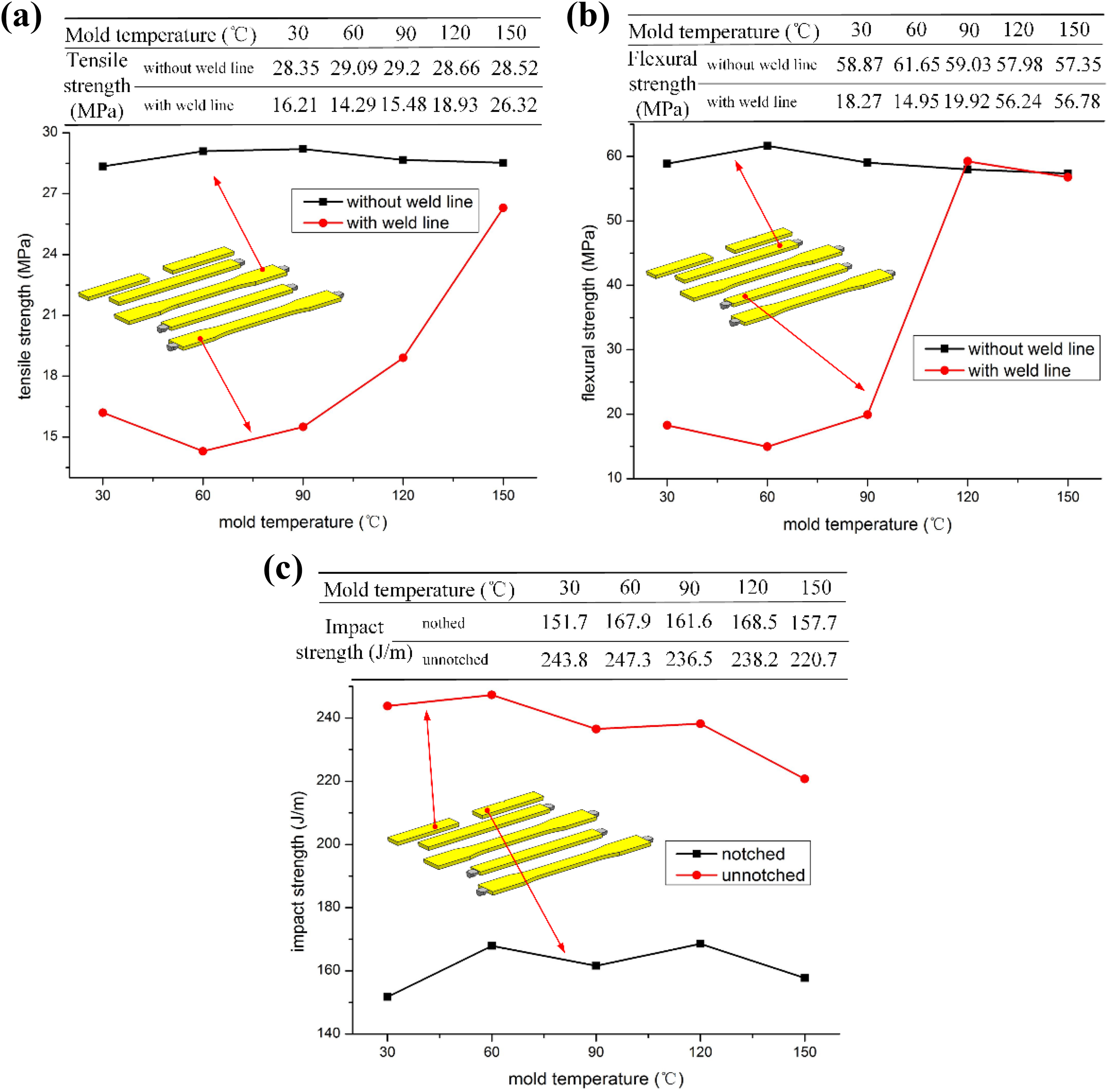
Mechanical properties and their variations of MIM molded parts with different mold temperatures: (a) tensile strength; (b) flexural strength; and (c) impact strength.
It can be seen from Figure 9(a), for MIM molded parts, the tensile strength of molded samples of single gate without weld line is much bigger than that of molded samples of double gates with weld line. With the increase of mold temperature, the tensile strength of molded samples of single gate without weld line changes very little, but the tensile strength of molded samples of double gates with weld line increases significantly. When the mold temperature increases to 150°C, the tensile strength of molded samples of double gates with weld line nearly reaches to that of molded samples of single gate without weld line. As shown in Figure 9(b), the increase of mold temperature has a similar influence on the flexural strength of MIM molded parts to the tensile strength. With the increase of molded temperature, the flexural strength of molded samples of single gate without weld line changes slightly, while the flexural strength of molded samples of double gates with weld line improves significantly. Especially, when the mold temperature increases to 120°C and over, the flexural strength of molded samples of double gates with weld line reaches an equivalent level to the flexural strength of molded samples of single gate without weld line. Finally, it can be seen from Figure 9(c), different from effect of mold temperature on the tensile strength and flexural strength, the effect of the mold temperature on the impact strength of MIM molded parts is weak. For the V shape notched impact samples, with the increase of mold temperature, the impact strength fluctuates slightly with firstly increasing and then decreasing with the increase of mold temperature, while for the unnotched impact samples, their impact strength only decreases a little.
Summarizing the above analysis about the effect of DMTC on mechanical properties of MIM molded parts, it can be seen that, for the molded parts of single gate without weld line, the increase of mold temperature has a very slight influence on their tensile strength and flexural strength, while for the molded parts of double gates with weld line, the increase of mold temperature has an obvious influence on their tensile strength and flexural strength, especially when the mold temperature is over the glass transition temperature of polymer materials, the tensile strength and flexural strength of molded parts of double gates with weld line increase sharply and quickly to reach an equivalent level to the molded parts of single gate without weld line. Considering the effect of DMTC on melt pressure in MIM process and the cellular structure of MIM molded parts together, it can be concluded that, under DMTC conditions, when the mold temperature increases to the glass transition temperature of polymer materials and over, the melt pressure in MIM process and the cellular structure of MIM molded parts change obviously. Although such change only has a slight influence on the mechanical properties of molded parts of single gate without weld line, it indeed improves the tensile strength and flexural strength of molded parts of double gates with weld line significantly.
Conclusions
In this article, the effects of DMTC on melt pressure, cellular structure, and mechanical properties of MIM molded parts were investigated experimentally by utilizing the constructed MIM test line with DMTC. The following conclusions were drawn:
Compared with the CIM, the melt pressure in the cooling stage of MIM process has an obvious foaming pressure instead of zero. With the increase of the mold temperature during the filling stage, the duration of foaming pressure in the cooling stage is increased, the melt foaming process is lengthened, and the foaming strength is improved.
With the increase of mold temperature in the filling stage, the average cell diameter of MIM molded parts increases, the cell density of MIM molded parts decreases, the cell diameter dispersion of MIM molded parts increases, while the thickness of unfoamed skin layer only changes a little. The turning point of mold temperature after which the cellular structure in MIM molded parts generates a significant change is around the glass transition temperature of the polymer material, for the used material and the processing conditions in this study, the turning point is about 90°C.
Under DMTC conditions, with the increase of mold temperature, the tensile strength, flexural strength, and impact strength of MIM molded specimens of single gate without weld line only change a little. But the tensile strength, flexural strength of MIM molded specimens of double gates with weld line increase significantly, and they reach the equivalent level of specimens of single gate without weld line when mold temperature increases to 120°C and over.
Footnotes
Declaration of conflicting interests
The author(s) declared no potential conflicts of interest with respect to the research, authorship, and/or publication of this article.
Funding
The author(s) disclosed receipt of the following financial support for the research, authorship, and/or publication of this article: This work was supported by the Climbing Program for Taishan Scholars of Shandong Province of China [No. TSPD20110804], National Natural Science Foundation of China [No. 51675308], China Postdoctoral Science Foundation [No. 2018M632671], and the project was supported by State Key Laboratory of Materials Processing and Die and Mould Technology, Huazhong University of Science and Technology [No. P2018-002].