
Abstract
A method is presented for computing and displaying the Maxwell (two-dimensional) or Rankine (three-dimensional) diagram reciprocal to a truss under load. Reciprocals are constructed via the two-dimensional Airy stress function or its three-dimensional analogue. A linear combination of the coordinates of each original node and the coordinates of its reciprocal object leads to the finished diagram. This is related to an underlying Minkowski sum of the polyhedral stress functions of the original and reciprocal diagrams. Some regions of the resulting combined diagram have units of length
Keywords
Introduction
Graphic statics has long been popular in architectural engineering, as it gives an appealing visual representation of the forces carried by the members of a loaded two-dimensional (2D) truss. The underlying geometry is that dictated by the rules for constructing Maxwell 1 reciprocal figures. There are two possible constructions for reciprocal diagrams, as forces may be drawn either parallel or perpendicular to their associated bars. In 2D, the difference is of little consequence. The Cremona convention draws bar forces parallel to bars, and the Maxwell convention draws bar forces perpendicular to bars. Cremona and Maxwell reciprocal diagrams are thus identical up to a 90° rotation. For three-dimensional (3D) trusses, the difference is more significant. In 3D, the Cremona 2 representation again has forces as lines parallel to the bars. In the perpendicular construction of Rankine, 3 forces are represented by polygons perpendicular to each bar. This article concerns only the perpendicular constructions, these being Maxwell reciprocals in 2D and Rankine reciprocals in 3D.
A Rankine diagram, if it can be constructed, may be complicated and difficult to understand by visual inspection. Maxwell 4 noted that ‘the mechanical interest of reciprocal figures in space rapidly diminishes with their complexity’. However, by combining the advantages of modern computer graphics that were unavailable to Maxwell with the Minkowski sum construction of this article, the accessibility and understanding of reciprocal figures in space may be increased.
Given the absence of elasticity from the construction that will be developed here, the method aligns itself more closely with plastic design than with the elastic structural analysis. It is no coincidence that the resulting figures are strongly similar to the strut-and-tie diagrams used in the lower bound plastic design of deep beams, corbels and the like, 5 and which now underpin much of modern masonry design and analysis. Moreover, the correspondence between the (equilibrium) states of self-stress of a 2D truss and the rotations of (compatible) yield line plastic collapse mechanisms of a slab 6 suggests that the technique may find applications beyond the design of trusses.
This article draws heavily on the pioneering 19th-century works of Maxwell,1,4 Rankine, 3 Cremona 2 and many others and on more recent extensions, particularly by Crapo and Whiteley,7,8 Akbarzadeh et al.9,10 and Pottman et al. 11
The procedure adopted here for constructing 2D reciprocals is that outlined in McRobie et al. 12 and Mitchell et al. 13 in this volume. It involves taking the normals to the plane faces of polyhedral Airy stress functions.
A simple illustration
Figure 1 (after Figure 1 of Maxwell 1 ) shows a six-bar truss and its reciprocal, these being 2D projections of dual tetrahedra. (Strictly, duality here refers to a polarity with respect to a paraboloid of revolution, as described in Maxwell. 4 ) One figure (the ‘form’ diagram) may represent bar lengths, while lengths in the other figure (the ‘force’ diagram) represent the bar forces of an equilibrium state of self-stress. Via the duality of 3D projective geometry (nodes, lines, areas) of one correspond, respectively, to (areas, lines, nodes) of the other.
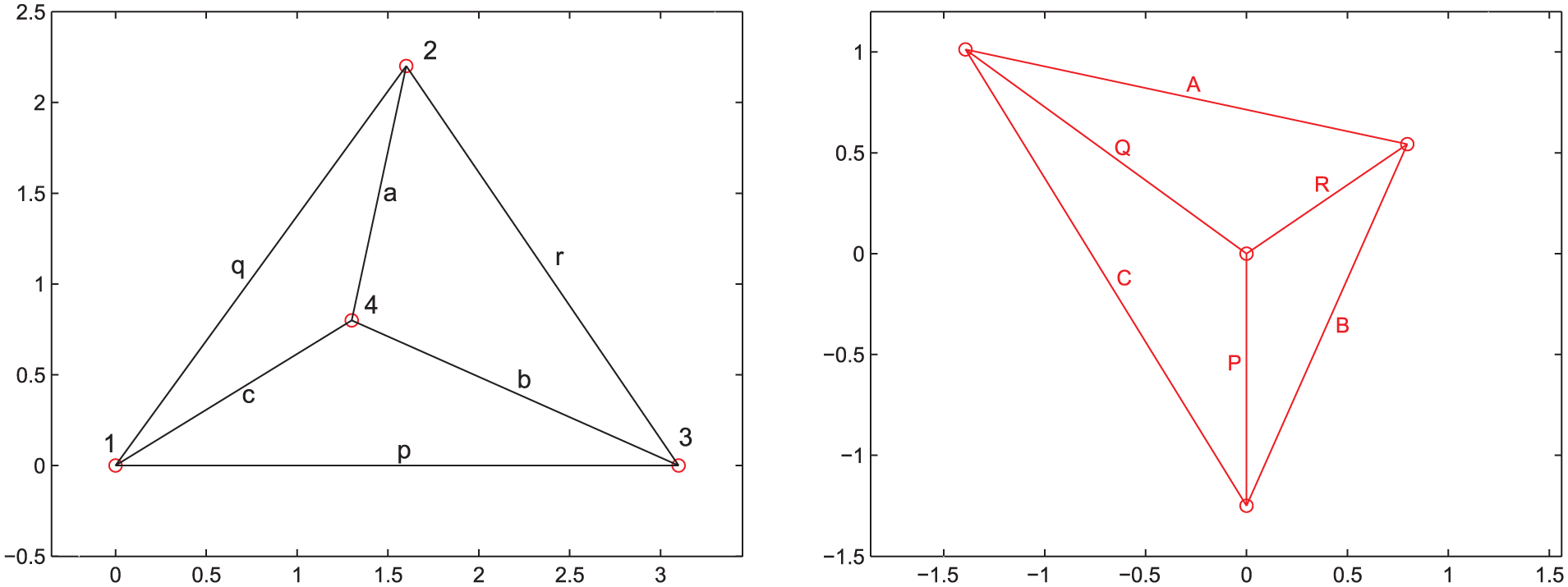
A simple truss and its reciprocal (after Maxwell 1864 Figures 1 and I).
Each diagram may be cut apart into its component areas (see Figure 2). This gives four triangles for each figure (the three smaller triangles and the overall surrounding triangle). These eight pieces may be rearranged as follows. At each corner of the large original triangle

A Maxwell–Minkowski diagram that combines the reciprocal pair of Figure 1.
Consider bar
The construction may be repeated with the remaining polygons, but with the form or force roles reversed. The large reciprocal triangle
Remarks
This simple construction leads immediately to a number of rather novel perspectives:
The diagram has the unusual property that some regions (e.g. the original triangle
The areas of the rectangles correspond to the
The aspect ratio of each rectangle (e.g.
The construction can be generalised to combine diagrams which are only topologically (rather than geometrically) reciprocal. For example, corresponding lines in the two diagrams need not be perpendicular. In that case, the rectangles of the Maxwell–Minkowski combination become parallelograms. These provide a visual representation of the various statements of virtual work. For example, one figure may represent bar forces
It is apparent that if the original and reciprocal diagrams are arbitrarily and separately rescaled, a Maxwell–Minkowski diagram can still be constructed. If the pieces of one diagram are rescaled, the connecting work rectangles simply rescale in one direction such that all the pieces are still sensibly connected. This leads to the construction of an interesting higher dimensional object, which can be loosely described as
The traditional interpretation of the force diagram is that lengths of lines denote magnitudes of forces. An equivalent perspective is to consider those lengths to be the bar thicknesses that would be required in a constant stress design. (In 2D, ‘stress’ means the tension force per unit distance transverse to the bar.) The usefulness of this notion becomes apparent when applied to a Maxwell–Minkowski diagram where the scaled original diagram dominates (such as
The final point is perhaps the key to the usefulness of the Minkowski construction when applied to Rankine reciprocals of 3D trusses. The Rankine diagram, where areas represent forces, is often complicated, and the physical meaning of the many shapes is difficult to discern visually. However, for the
Construction details
In cases more general than the simple example, construction is readily implemented by addition of (scaled) original and reciprocal coordinates. That is, at original node

then defines a cell. Nodes on corresponding sides of such cells may then be connected by lines parallel to the original members.
As an alternative to the last step, the cells may be connected by reversing the process, taking a reciprocal node
then defines a cell which connects the cells of the first construction, thereby completing the diagram (including the rectangles or prisms).
Alternatively again, one may choose to draw only the rectangles or prisms that connect the cells, and this implicitly draws the scaled original and reciprocal cells.
Reciprocal diagrams were constructed via the method described in Mitchell et al.
13
and McRobie et al.
12
That is, drawings in 2D
This procedure readily generalises to the 3D Rankine construction. That is, drawings in 3D
The Minkowski sum
Given two sets

The Minkowski sum of two tetrahedra.
The combined polyhedron is a cantellated tetrahedron, which is topologically a cuboctahedron. Indeed, the overall procedure may be viewed as cantellation of the original polyhedral stress function. Loosely speaking, a cantellation of a polyhedron involves bevelling its edges and truncating its vertices. A vertex is truncated such as to expose the polygonal face reciprocal to that vertex, and the bevelling is such as to match the edges of the reciprocal polygons that were created by the truncation. Cantellation of the polyhedral stress function thus gives another geometric method of creating reciprocal diagrams since it leads directly to the combined Maxwell–Minkowski polyhedron, from which the reciprocal diagram may be extracted.
For Rankine–Minkowski diagrams, the procedure is similar. The 3D original and reciprocal polyhedra are lifted to stress functions in 4D where the Minkowski sum is performed and then the combined polytope is projected back to 3D.
Whether the diagrams that we are calling Maxwell–Minkowski and Rankine–Minkowski diagrams are indeed the projection of Minkowski sums in more complicated cases (such as those involving non-convex polyhedra or polytopes) is a matter for further discussion. It does not affect the validity of the construction, which is defined by the summation of original and reciprocal coordinates (equations (1) and (2)).
Examples
In each of the following examples, Maxwell–Minkowski diagrams are given for the five cases of
2D Maxwell–Minkowski
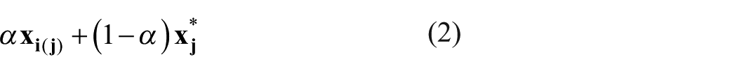
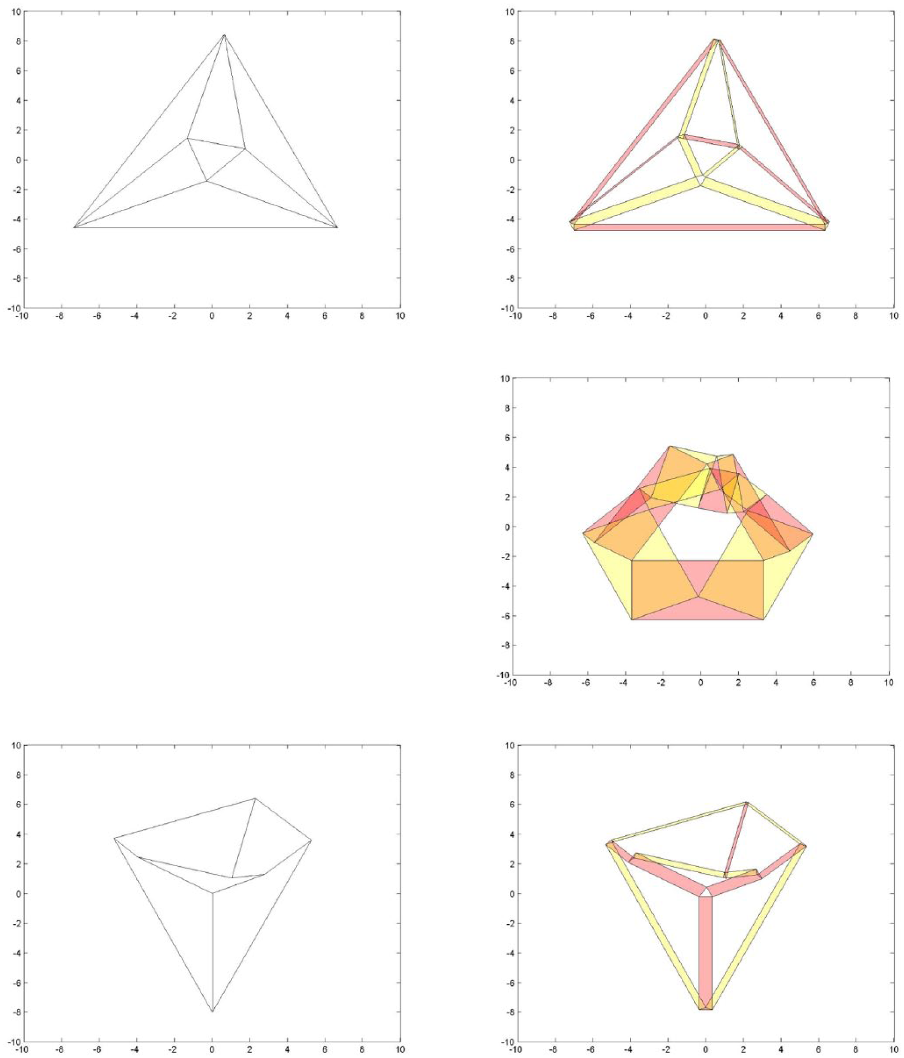
Figure 4 is based on Maxwell 1864 Figure 1 and illustrates the example considered in section ‘Introduction’, where the form and force diagrams each are the projection of a tetrahedron. In each subfigure, the sum of red and yellow areas is equal, illustrating Maxwell’s load path theorem. The upper right subdiagram thus indicates a triangular compression hoop stressed by tension spokes, while the lower right shows a triangular tension hoop stressed by compression spokes.
Maxwell 1864, Figures 1 and I (tetrahedron). This is the example already considered in section ‘Introduction’, where form and force diagrams each are the projection of a tetrahedron. In each diagram, the sum of red and yellow areas is equal.
Figure 5 is based on Maxwell 1864, Figures 4 and IV. The reciprocal diagram shown in the lower left subfigure is in the classic Desargues configuration, requiring the radial lines to meet at a point. This is the same topology as the classic yield line mechanism for plastic collapse of a quadrilateral slab, the collapse mechanism resembling a downward-pointing hipped roof. The original diagram (upper left) has 2 degrees of freedom, in that independent stress functions may be generated by independently lifting the two central nodes (see McRobie et al. 12 and Mitchell et al. 13 for further discussion). The stress function applied here is chosen such as to match Maxwell’s original drawings. The Maxwell–Minkowski representation makes it evident that the original structure has a triangular tension hoop stressed by three compression spokes, while a second set of spokes provides some tensile resistance.
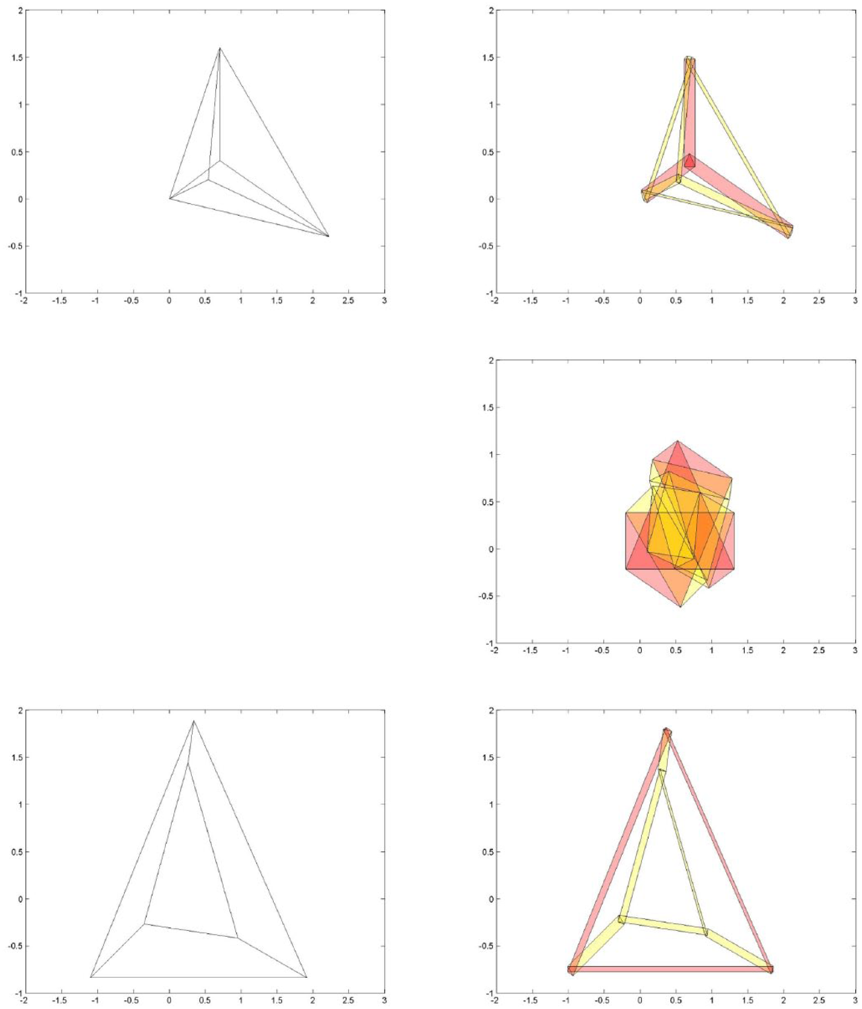
Maxwell 1864, Figures 4 and IV (Desargues 2D). The lower left subfigure is in the classic Desargues configuration, requiring the radials to meet at a point.
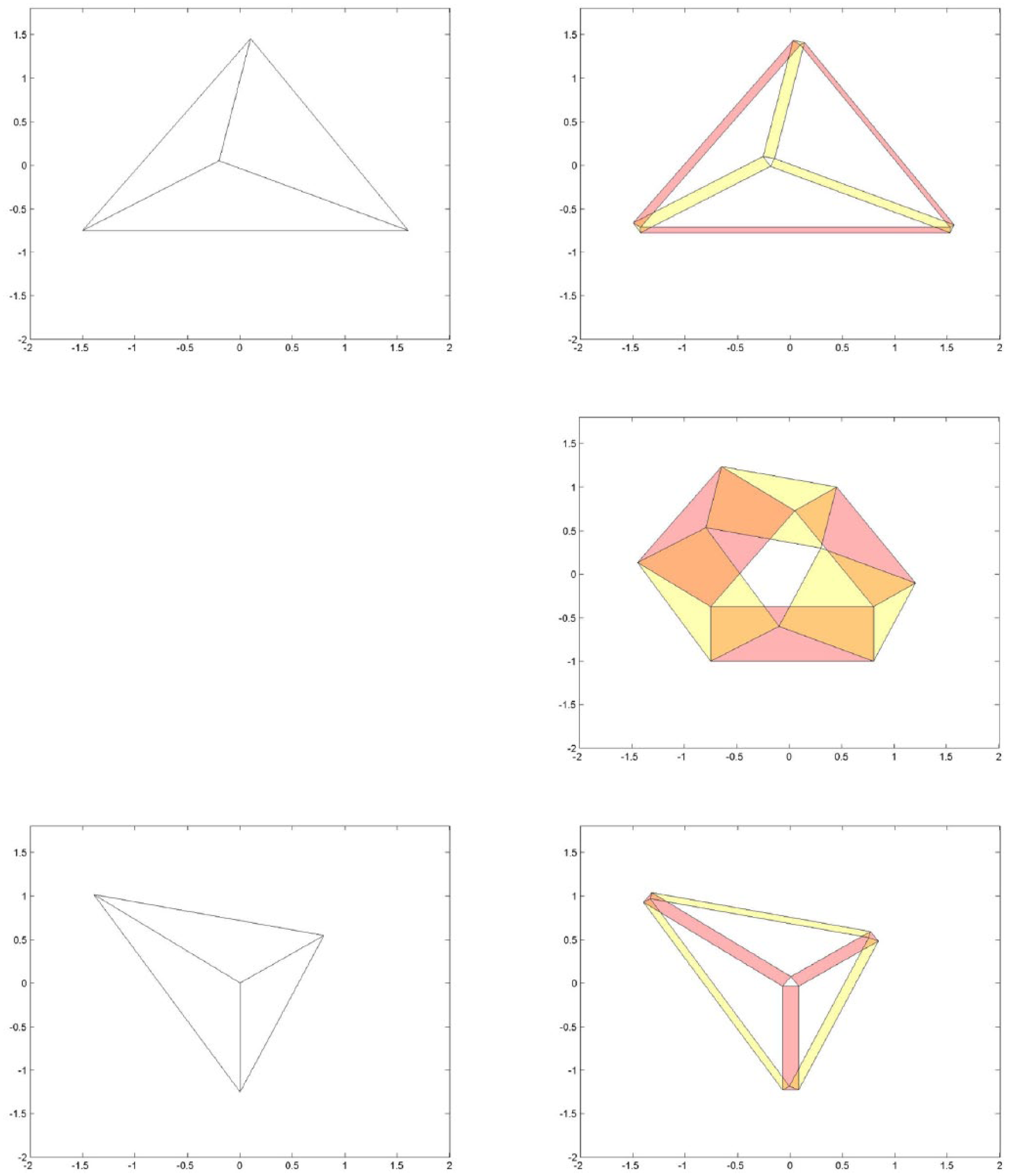
Figure 6 corresponds to Maxwell 1864, Figures 5 and V. The original (upper left) is the projection of an octahedron, and the reciprocal (lower left) is the projection of a topological cube or hexahedron. The stress function over the original has 3 degrees of freedom which may be mobilised by independently lifting the three inner nodes. 12 The particular reciprocal drawn corresponds to that chosen by Maxwell and which is also explored in Mitchell et al. 13 The dual stress function over the reciprocal has only a single degree of freedom. 12
Maxwell 1864, Figures 5 and V (octahedron or hexahedron). The original (upper left) is the projection of an octahedron, and the reciprocal (lower left) is the projection of a topological cube or hexahedron. The original has 3 degrees of freedom which may explored by lifting the three inner nodes. The particular reciprocal drawn is that of Maxwell, 4 which is revisited in McRobie et al. 12 and Mitchell et al. 13 The reciprocal has only a single degree of freedom.
Figure 7 is based on a bridge optimisation exercise.
15
The form diagram is shown in the top left subfigure. The upper part of this subfigure is the bridge, and the lower part is a funicular system through which vertical loads can be applied to the bridge. (The use of a funicular in this manner is described in McRobie et al.,
12
such that structures subject to external loads can be treated by the same techniques as were developed for self-stresses alone.) The

Based on a bridge optimisation exercise,
15
the Maxwell–Minkowski construction gives visual expression to the
3D Rankine–Minkowski
Figure 8 is a higher dimensional generalisation of the 2D Desargues configuration of Figure 5. In this case, the form diagram (upper left) consists of two tetrahedra whose nodes are connected by four lines, and those four lines meet at a point (not shown), such that each quadrilateral between the two tetrahedra is a planar polygon. This figure demonstrates the visual power of the Rankine–Minkowski procedure. Reciprocal to the 3D Desargues configuration is the force diagram (lower left) which consists of a number of connected triangles whose areas represent the force magnitudes in their dual bars. This diagram is not easy to understand. However, in the

Desargues 3D. This higher dimensional version of the Desargues configuration of Figure 5 demonstrates the visual power of the procedure. The force diagram (lower left) – consisting of a number of connected triangles whose areas represent the force magnitudes in their dual bars – is not easy to understand. However, in the
Figure 9 shows the projection of a 4D hypercube, a tesseract (upper left), and its reciprocal, a 16-cell reciprocal (lower left). Just as the previous figure had upper and lower tetrahedra stressed against each other, so here there are upper and lower cuboids similarly stressed. The upper cuboid of the tesseract has been extended upwards such that the figure can be interpreted as a column-supported mansard roof carrying vertical loads from the peaks on its upper ridges. The lower part of the tesseract acts as a funicular, and loads can be applied via a stress function which lifts the central cuboid into 4D. While the 16-cell reciprocal is somewhat difficult to understand, the
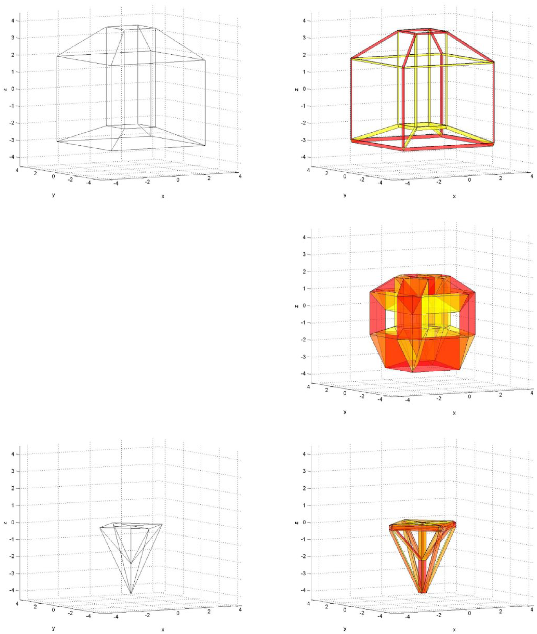
Tesseract (mansard roof). The original and reciprocal are the projections of a tesseract and 16-cell, respectively. The original could represent a column-supported mansard roof with vertical forces applied via a funicular below. Loads were applied via the stress function, lifting the central cuboid into 4D. The
Figure 10 is also based on the projection of a tesseract. This time the central cuboid is contained within the outer cuboid (upper left subfigure), but the upper cuboid has been cross braced by members connecting at a central node. Much as before, a system of stresses may be induced via a stress function which lowers the central cuboid into the fourth dimension,
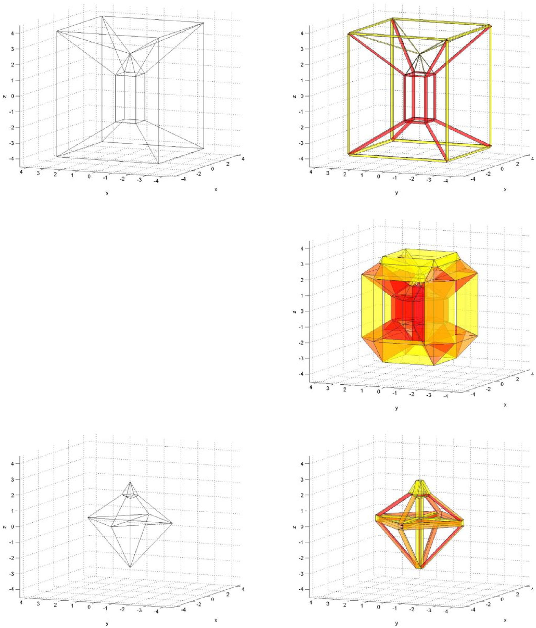
Stansted. This example generalises the previous tesseract by adding a bracing system into the upper cuboid. This gives an additional state of self-stress that can be varied separately. One interpretation is that the central cuboid and the braced upper cuboid constitute one of the tree structures supporting the roof at Stansted Airport, and carrying vertical loads at its outer corners.
Figure 11 shows Jessen’s orthogonal icosahedron, a tensegrity structure which is known to possess a state of self-stress. However, since the structure has only a single three-cell volume, the icosahedron, its 4D projective geometry reciprocal (i.e. the Rankine diagram) consists of only a single point, which is incapable of representing a state of self-stress. A meaningful Rankine reciprocal can, however, be constructed by adding a central node connected to all other nodes by radial bars (a procedure known as ‘coning’). The ‘coned’ icosahedron is thus triangulated internally by 20 tetrahedra. Lifting the central node into the fourth dimension and taking normals lead to a non-trivial Rankine reciprocal (lower left). When combined with the original in an
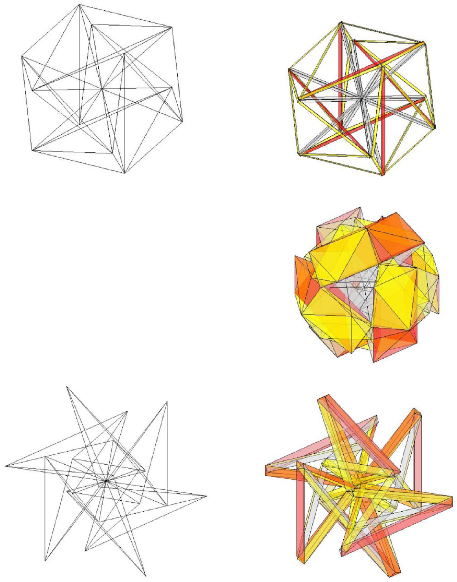
Jessen’s orthogonal icosahedron. This final example considers the icosahedral tensegrity structure (upper left). The tensegrity possesses a state of self-stress, which can be activated in the Rankine construction via ‘coning’. That is, an additional node has been placed at the centre, connected to all other nodes via bars of zero area (grey).
Rankine incompleteness
Unfortunately, not every self-stressed 3D truss has a meaningful Rankine reciprocal. The general issue is covered in Crapo and Whiteley. 7 For the icosahedral tensegrity above, the problem was solved by adding a further node which connected to the structure with bars of zero area. However, it is not yet clear whether similar procedures will be sufficient in all cases. However, such difficulties concern the Rankine construction rather than the Minkowski construction: if a structure has a meaningful Rankine reciprocal, the two can be combined to create a Rankine–Minkowski diagram.
Indeed, the Minkowski construction is an aid to understanding why Rankine diagrams do not always exist. For example, the force in a single bar may be in equilibrium at one end with the forces in three bars that join there. Around that node, a Rankine tetrahedron may be defined whose face areas are proportional to the four forces meeting there. At the node at the other end, three other bars may meet with the four forces there being in equilibrium, and again, a Rankine tetrahedron may be defined. In general, although the triangles at each end that represent the force in the bar under consideration will have equal areas, they need not be similar triangles. They thus cannot be ‘extruded’ along the bar to create a prismatic Rankine–Minkowski representation and cannot be glued to form a Rankine reciprocal.
The 3D Desargues configuration of Figure 8 is another case in point. In that example, the four lines which connect the nodes of the upper tetrahedron with those of the lower one, when extended, meet at a point, analogous to the 2D case. However, equilibrium configurations exist which have the same bar topology, where the four lines do not meet at a point (although they must, however, all intersect at some line). Some ‘faces’ of these configurations are what Maxwell calls ‘gauche polygons’, meaning that while they are defined by a closed circuit of lines, those lines need not lie in a single plane. Such ‘faces’ are not planes, and thus, the projective geometry duality breaks down.
The incompleteness arises from the use of the single stress function in 3D. For 2D stresses, the Airy stress function gives a complete description. For 3D stresses, Maxwell 4 described two stress function methods. One method corresponds to that used here to create the Rankine reciprocal, with Maxwell noting that the description was incomplete. Maxwell’s other method involved three separate stress functions, and while that method is complete, it corresponds to the Cremona description where bar forces are represented by vectors parallel to the bars.
It is not the purpose of this article to resolve the incompleteness of the Rankine description. This remains a topic for further research. Instead, the intention here is to show how the Maxwell and Rankine constructions can be augmented to give Maxwell–Minkowski and Rankine–Minkowski diagrams which are conceptually simple and yet which can provide much insight.
Summary and conclusion
The Minkowski sum construction for Maxwell and Rankine diagrams provides insight into the internal forces carried by 2D and 3D trusses under load. In 2D, the Maxwell description is complete, but the Rankine description in 3D is incomplete. Nevertheless, the Minkowski constructions shown here may prove to be of use and not only in truss design but also in various other spheres of structural engineering.
Footnotes
Acknowledgements
The author is grateful for conversations with Bill Baker, Marina Konstantatou, Toby Mitchell, Elissa Ross and Walter Whiteley. Much of the impetus for this work occurred as a result of the workshop on Advances in Combinatorial and Geometric Rigidity at the Banff International Research Station, 12–15 July 2015, organised by Robert Connelly, Steven Gortler, Tibor Jordan, Brigitte Servatius, Meera Sitharam and Walter Whiteley.
Declaration of conflicting interests
The author(s) declared no potential conflicts of interest with respect to the research, authorship and/or publication of this article.
Funding
The author(s) received no financial support for the research, authorship and/or publication of this article.